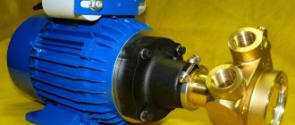
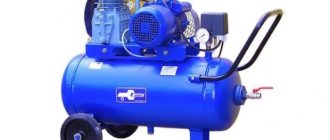
Deep-rod pumps, which are designated by the abbreviation SHRP, are devices that can be used to pump out liquid media from wells characterized by significant depth. The use of such pumping equipment is one of the most popular methods of pumping out oil: approximately 70% of oil-bearing wells operating today are served by rod pumps.
Oil well equipped with a sucker rod pump
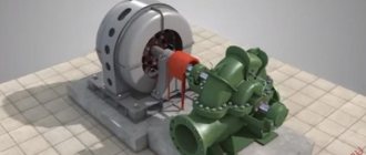
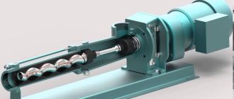
Elements of pumping units
The borehole pumping unit has an SSN drive, which allows the object to be moved directly under the influence of sucker rods. Among its main operating elements, according to GOST 2002, well sucker rod pumps stand out:
- one-piece fixed-type cylinder with extensions;
- movable pump plunger;
- valves, including suction and discharge valves;
- locks.
Each of the CH extensions is screwed onto the cylinder from all sides. They must push the plunger out of it while the pumping structure is operating. Industrial well rigs operate without residual deposits inside the stationary cylinder. As a result, the plunger does not jam, so the repair of rod pumps can be carried out without any problems. Insert pumps used in domestic industry are equipped with the following types of components:
- Castle support.
- Cylinder.
- With a plunger.
The borehole pump installation is under tension, so high-alloy steels are required to manufacture parts for various types of well pumps or sucker rod pumps. The duration and reliability of the useful use of pumping equipment depends on these materials. The tightness of their fit is ensured by the high precision of the production of parts for pumps. This also applies to threaded connections. All elements of the installation are completely interchangeable. Among the main elements of its design, there is a ground part, consisting of the following links, which are:
- Column.
- Chain with tension screw.
- Counterweight with stop.
- Suspensions (cable rope, wellhead rod).
- Rope block assembly.
- Tooth coupling.
- Asterisks driven and leading.
- Rope slip limiter.
- Fencing and compartment door.
- Belt drive casing.
The design of the pumping unit with an electric motor and control station provides several platforms:
- driven sprocket maintenance;
- gearbox;
- rope blocks;
- front rotary.
The equipment has a complex, which is a ground segment of the installation, which is called a pumping machine. The elements of this design remained unchanged for many years. The installation with a differential converting mechanism and gearbox is equipped with a V-belt drive that allows you to drive the pumping machine.
Russian enterprises produced exclusively the chain drive for sucker rod pumps. The devices that replaced the manual pump have been still in the process of improvement since 2002.
This is interesting: Deep well pumps: operating principle, types, selection rules
Operating principle of SRP
- Operating principle of SRP
- Types of sucker rod pumps
- Advantages and disadvantages of pipe and insert pumps
- Operating principle and marking of a rod pumping unit
- Sources:
SRP pumps are designed for pumping liquids from wells with a temperature of no more than 130 degrees, water cut of no more than 99% by volume, viscosity of up to 0.3 Pa*s, mechanical impurity content of up to 350 mg/l, and free gas at the intake of no more than 25%.
The sucker rod pump consists of a solid fixed cylinder, a movable plunger, suction and discharge valves, a lock (for plug-in pumps), connecting and installation parts.
A plunger pump consisting of a cylindrical body 1 (cylinder), inside of which there is a hollow piston 2 (plunger), is lowered into the well on a string of lifting pipes. A discharge valve 3 is installed in the upper part of the plunger. A suction valve 4 is installed in the lower part of the stationary cylinder. The plunger is suspended on a column of pumping rods 5, which transmit to it reciprocating motion from a special mechanism (pumping machine) installed on the surface.
As the plunger moves upward, liquid from the well enters through the suction (receiving) valve into the pump cylinder, since a pressure is created under the plunger much less than in the well. As the plunger moves downwards, the suction valve closes under the action of liquid pressure under the plunger and the volume of liquid from the cylinder through the hollow channel of the plunger and the open discharge valve, the opening of which occurs from the pressure of the liquid under the plunger and the hollow channel of the plunger, enters the lifting pipes.
During continuous operation of the pump, the liquid fills the volume of the lifting pipes and is then directed to the surface.
The most widely used types of pumps are: inserted and non-inserted (pipe).
Rod pumps are used to supply fluid from deep wells. Most often, a sucker rod pump is used in oil production.
A check valve is installed in the piston of the rod pump, allowing fluid to flow in one direction.
The closing element of the presented valve is a ball.
As the piston moves downward, the ball moves up and the valve opens, allowing fluid to pass through the piston.
When the piston moves upward, the ball is pressed against the seat, and the valve closes under the pressure of the liquid column.
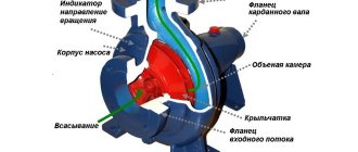
Design features and principle of operation
The main design elements of a sucker rod pump, which is placed in a well on a special column consisting of lifting pipes, are:
- a cylindrical body, in the inner part of which a hollow piston (displacer), called a plunger, is installed;
- a discharge valve installed in the upper part of the displacer;
- a ball-type suction valve, which is located in the lower part of a fixed cylindrical body;
- pumping rods connected to a special mechanism (pumping unit) and a plunger and imparting to the latter a reciprocating movement (the pumping unit itself, which drives the downhole rod pump (SRP), is mounted outside the well - on the surface of the earth).
The device of a sucker rod pump
The operating principle of deep-well sucker rod pumps is quite simple.
- When the plunger moves upward, a vacuum of pressure is created in the lower part of the pump chamber, which facilitates the suction of the pumped liquid medium through the inlet valve.
- When the plunger begins to move downwards, the suction valve closes under the influence of the pressure of the pumped liquid medium, and it begins to flow into the lifting pipes through the hollow channel of the piston and the discharge valve.
- During the non-stop operation of a deep-rod pump, the liquid medium it pumps begins to fill the internal volume of the lifting pipes and is ultimately directed to the surface.
Operating principle of SRP
Terms of use of ShSN
Manufactured types of downhole sucker rod pumps lift liquid. The state standard provides for the division of tubing columns according to the fastening method into 2 types:
- Plug-in (NSV).
- Non-insertable (NSN).
A pipe pump or pump, having a VC (suction valve) seat, is equipped with a cylinder, which is lowered into the well on the tubing. The plunger, which contains valves, must be lowered into the well before the suction, and then enters the cylinder. This is done through rods. To ensure the connection of the installation plungers with the balls of suction-type valves, special rods are used.
The disadvantage of the NSN is not only the complexity of the assembly process, but also the long time it takes to lift the device to the surface. Eliminating structural faults is difficult. Insert pumps are assembled on the surface, and then they are lowered underground on rods inside the tubing columns to a certain depth of the well.
A pipe well pump requires that when lifting the pump cylinder of the installation from underground, it must be removed entirely. This condition is considered the main distinguishing feature of NSN from NSV. Insert pumps increase the speed of hoisting operations by 2-2.5 times, which facilitates the work of workers carrying out well repairs.
An insert pump has a lower flow rate than a non-insert pump. This is due to the presence of pipes of a given diameter. The descent of the NSV is carried out on rods, and the strengthening or compaction of the element, if there are landings, is carried out on the locking support of the cylinder. It should descend onto the tubing.
The lifting of the pump from the oil well using the NSV should be carried out simultaneously with the removal of the rod string at a significant depth of descent. Operation of the NSV is carried out if the well has a low flow rate. The movement of the NSN plunger is vertical, since the descent and ascent are carried out through the rods.
The term "gas"
Gas is a state of matter. There are four possible known states - solid, liquid, gas and plasma. In the gaseous state, the atoms and molecules that make up the substance move freely, almost chaotically, in the intervals between collisions, during which a sharp change in the nature of their movement occurs. Surprisingly, the most common state of matter in the Universe is the gaseous state. The atmospheres of planets, the sun, stars, nebulae, clouds of interstellar matter and much more consist of gases - neutral or ionized.Gases are also widespread inside our planet, in nature: they, as already mentioned, make up the atmosphere, are dissolved in rivers, seas and oceans, and are also found in significant quantities in the bowels of the earth. By uniformly filling various available spaces, gases exert less pressure on the spatial shell than liquid and solid substances, and the volume of a gaseous substance largely depends on pressure and temperature.
As we know from school, the main properties of gases are transparency, colorlessness and lightness. However, these same properties made it difficult to study gases for a long time, so the sections of physics and chemistry responsible for the gas study sector developed more slowly than others.
An ordinary person, without the proper high-tech equipment, will not be able to sense or observe the gas; the existing senses are not enough for this. Therefore, gases are usually described by the following characteristics: number of particles (mol), volume of substance, pressure and temperature. These four quantities for characterizing gaseous substances were invented and comprehensively studied by scientists such as Boyle, Dalton, Gay-Lussac, Avogadro and Charles, who established that under different conditions for different gases, certain characteristic values are correct. By establishing a connection between different properties and characteristics of gaseous substances, a mathematical equation of state for an ideal gas was found.
Pascal also made a significant contribution to the study of gas, who proved that in the absence of gravitational and pressure forces, the gas will be the same at all points, which is possible to observe in space in modern times. This axiom is equally opposite for the observation of gas in the earth’s atmosphere and nature, where the force of gravity will influence the structure of the substance, accordingly making the gaseous mixture inhomogeneous. A simple proof of this dogma is to inflate a balloon with helium, which, as you know, is lighter than air, and release it into the sky; the balloon itself will fly up.
Gases always mix. And they have good compressibility - the higher the pressure, the greater the density of the gaseous substance. The transition of a gas from its usual state into a liquid is called evaporation; anyone who has boiled water on the stove at least once is familiar with this phenomenon, when the steam coming out of the pan, when cooled by air, turns into drops of liquid. And the transition to a solid state is sublimation. In nature, there are gaseous substances that can become a solid without going through the liquid phase of evaporation.
Types of sucker rod pumps
There are two main types of sucker rod pumps:
- plug-in
- pipe (non-insert)
Pipe Rod Pump
The pump plunger moves in a sleeve that is attached to the pipe string. The sleeve is installed in the well along with the pipes; in addition, it can only be removed together with the pipes.
There is a check valve 1 in the plunger. Another valve 2 is attached to the bottom of the sleeve.
When the plunger moves downwards, valve 1 opens, passing liquid from the well into the cavity above the plunger, valve 2 is closed at this moment.
When the plunger moves up, valve 1 closes, the plunger displaces liquid up the well. Valve 2 is open at this moment, fluid from the formation fills the cavity in the well.
Insert Rod Pump
The plunger and sleeve of the plug-in rod pump are placed in the already installed pipe string.
When the plunger moves downwards, valve 1 opens, allowing liquid to pass through, valve 2 is closed.
When the plunger moves up, valve 1 closes, allowing the liquid to flow back, the liquid rises up the well. Valve 2 is open at this moment, liquid from the formation flows under the plunger.
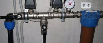
Types of wellhead equipment
A wellhead rod, which is a special rod, is necessary to connect the rod column to the rope suspension. It has a polished surface and is produced without heads with the type of thread provided by the standard. To protect the polished rod from corrosion, painting, galvanizing, and inhibition are carried out. The functions performed by the PS wellhead equipment are as follows:
- ensuring sealing of the annulus;
- well production withdrawal;
- tubing suspension.
The pumping unit is equipped with wellhead equipment, including:
- Wellhead seal. Provides sealing of the outlet of the wellhead rod due to the stuffing box head.
- Tee. It is screwed into the tubing coupling; it is necessary for the removal of well products.
- Cross. Allows you to hang the tubing string on a cone in order to correctly position it relative to the well axis.
- Shut-off valves and check valves.
A ball joint is provided for self-installation of the stuffing box head. This is ensured in case of misalignment of the stuffing box rod and tubing, whose axes do not coincide. This is important to prevent wear of the sealing packing and to make it easier to change the special packing. The presence of a cross allows the instruments to be lowered into the annulus through a wellhead pipe with a valve.
This is interesting: Repair of centrifugal pumps - maintenance, adjustment, types of malfunctions
Complete set of pumping machine
Among the components of the pumping machine the following stand out:
- Frame.
- A stand in the form of a truncated 4-sided pyramid;
- Balancer equipped with a rotating head.
- Traverse with connecting rods.
- Gearbox.
The SK package includes a set of pulleys that allow you to change the number of swings by discrete regulation. Changing and tensioning engine belts occurs quite quickly using a rotating frame-slide. The pumping machine is installed on a frame mounted on a reinforced concrete foundation. To fix the pump balancer, a pulley is used, which is called a brake drum. The head ensures the passage of the pumping unit during the process of repairing a well underground.
The movement of the balancer head in an arc involves its connection with the rods and the wellhead rod due to a flexible rope suspension that regulates the fit of the pump plunger into the CH cylinder. The amplitude of movement of the head of the balancer is adjusted by changing the area of the articulation of the crank with the connecting rod relative to the axis of rotation. Moving weights onto the balancer balances the action of the pumping machine. The process is considered as a balancing, rotary or combined rod balancing.
Oil, Gas and Energy
Well operation is monitored by dynamometers, fluid flow rate measurements, wellhead pressures, and dynamic levels. The frequency of monitoring parameters is as follows;
Table 1
| Type of measurement | Periodicity |
| Fluid flow measurement | daily for 3 days after launch, |
| further according to the regulations | |
| Sampling for % H2O | once a decade, then according to the regulations |
| daily for 3 days after launch, | |
| further according to the regulations | |
| daily for 3 days after launch, | |
| further according to the regulations | |
| Determination of the coefficient | before implementation, during optimization, |
| productivity (KVU) | further according to the regulations |
| Sampling for EHF | from the killing solution, and then once every six months |
| Dynamometry | after starting the well, when changing the mode |
| (except SK type PF) | well operation and before well repair |
If the lower part of the rod string is broken or turned away, as well as in the presence of plunger seating during the move and high hydraulic resistance in the valves, a heavy bottom should be used for the rod strings.
According to the dynamogram readings, the degree of filling of the pump cylinder, the tightness of the discharge and suction valve and tubing columns, the degree of wear of the pump cylinder-plunger pair, the influence of gas on the filling of the cylinder, the turn-off or breakage of the sucker rod string, the jamming of the plunger can be determined. in the cylinder and other malfunctions in the operation of underground equipment.
Preventive inspection of ground equipment is carried out once every three days. When inspecting a working pumping machine, the CDNG operator must check:
- presence of vibration and unusual noises - visually and audibly. Determine which parts of the pumping machine are presumably their sources. If necessary, stop the rocking chair;
- balance according to ammeter readings. It is carried out after the well has reached its operating mode and after changing the operating mode of the well (balance is satisfactory if the difference between the ammeter readings during the up and down stroke does not exceed ± 10% of half the sum of the two maximum current values per cycle). If the SKN operates in an unbalanced mode, then it is stopped and an application is submitted to the PRCEO.
After stopping the vehicle (the head is in the down position, the brake is tightened), check:
- heating of the electric motor, gearbox - to the touch;
— condition of threaded connections (tapping);
- once every 7 days, check the oil level in the gearbox by inspecting the oil dipstick;
- tension the V-belts once a month - by testing. If necessary, replace the belts. Installation of new belts and old ones is not allowed. After replacing the belts, if the electric motor is not aligned, submit a request to the PRTsEO;
- seating the cranks on the low-speed gearbox shaft - visually (the cranks must be seated all the way into the grooves of the low-speed shaft). The keys should protrude from the shaft by no more than 20 mm);
— fastening counterweights to the cranks — visually (there should be no displacement during operation);
— connection of the crank with the lower head of the connecting rod — visually from the gearbox side (the pin should not rotate relative to the crank);
- alignment - visually. If the alignment is violated, submit a request to the PRTsEO;
— rope suspension of the stuffing box rod and wellhead stuffing box:
when the balancer head is in the lower position, the distance between the lower suspension beam and the wellhead seal must be at least 200 mm (visually);
- condition of the rope - visually (if the wires break, submit a request to the RPTSEO);
- oil leakage through the seal. If there are leaks, tighten or replace the oil seal;
— the state of fastening of the rope and rod in the suspension — visually.
In all cases of obvious breakdowns, inform the technician.
At each well, the cable suspension must be equipped with two traverses - upper and lower.
It is PROHIBITED to operate the well when:
— leaks through threaded connections and stuffing box seals;
— absence or malfunction of the IC fencing;
— extraneous noise in the gearbox or electric motor;
— malfunction of the control station;
— tightened lower seals;
— the oil level in the gearbox drops below the permissible level;
- an unbalanced rocking machine;
— unsmooth movement of the polished rod;
- non-centered SC.
Main varieties
According to their design, sucker rod pumps can be:
- plug-in;
- non-insertable.
Lowering of plug-in sucker-rod deep-well pumps into a well, as well as their removal from it, is carried out in assembled form. In order to perform such an operation, the plunger is placed inside the cylinder, and the entire structure on the sucker rods is lowered into the shaft.
Types of SRP pumps by method of attachment to the column
Plug-in SRPs are also divided into two types of devices:
- plug-in pumps with a top lock (HB1);
- pumps, the lock of which is located in their lower part (HB2).
Insertion devices are used primarily for servicing deep wells, which are also characterized by a small flow rate of the liquid medium pumped out of them. The use of such SRP pumps, to remove which it is enough to lift the rods to which the entire pump structure is connected, greatly simplifies well repairs if the need arises.
Scheme of operation of the installation with a sucker rod pump
In order to place a non-insert-type sucker rod pump into a well, more complex steps must be performed. A cylinder is first placed into the well, for which tubing is used, and only then, using rods, a plunger with valves is lowered into the already installed cylinder. Removing a deep-rod pump of this type is also carried out in two stages: first of all, the plunger with valves is removed from the pump cylinder, and then the cylinder with tubing is lifted from the well.
Non-insertable devices are also divided into several categories:
- pumping units without a catcher (LV);
- non-insert deep-well pumps with a gripping rod (НН1);
- non-insert pumps with catcher (НН2).
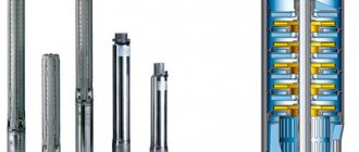
Deep-well sucker rod pumps are produced in various sizes and designs, including special orders for operation in special conditions
Among the types of non-insert equipment listed above, the most popular are devices equipped with a catcher (HH2). The high popularity of the latter is explained by the fact that the mechanism for emptying them is characterized by a simple design and, accordingly, greater reliability in operation.
The choice of equipment of a particular model is made depending on the specific operating conditions, as well as on the characteristics of the liquid medium that is planned to be pumped out with its help.
Downhole rod pump, version NN2B
SRP: advantages, disadvantages, scope of application
SRP are used to lift liquid media from wells from great depths. These are volumetric machines, which determines their properties - rigidity characteristics, relatively small feed rates, independence from pressure supply.
In more detail, deep-well sucker rod pumps have a fairly long range of advantages over other types of pumping devices - these are:
- high efficiency;
- possibility of using different types of engines;
- ease of maintenance and repair; in most cases, maintenance and repair work is possible in the field. Particularly easy to maintain and repair are plug-in sucker rod pumps, the sleeve and plunger of which are located inside the well string - they can be removed without the need to dismantle the pipe string;
- the ability to service sand-producing wells, pump oil with a gas component and a large amount of petroleum wax.
There were some downsides too. Deep rod pumps cannot be used in curved, horizontal wells; they are used with caution in deep mines - the deeper the well, the higher the risk of rod breakage.
Scope of application: pumping liquid media from deep wells. SRP is the most popular equipment for oil pumping: approximately 70% of oil-bearing wells operating today are serviced by sucker rod pumps. The remaining 30% is exploited through oil flowing due to reservoir energy (flowing can be natural due to pressure in the formation or artificial - due to the injection of liquid or gas into the well), or gas lift (if there is not enough momentum to lift the liquid, into the well the missing amount of gas is pumped from the surface).
#FORM#
Advantages and disadvantages of chain drive
Model PC-80x6.1 in our country is produced by Izhneftemash JSC. Domestic equipment was created based on the development of the American company Weatherford called Rotaflex. The drive structure is equipped with a frame, which is placed on a separate base. During the equipment assembly process, the following parts are installed on the frame:
- electric motor;
- gearbox;
- belt drive;
- driving and driven sprockets;
- carriages with counterweight;
- rod columns
To connect the elements, flexible links of a continuous type are used. In the oil industry, not only balancer drives, which are considered traditional, are widely used, but also non-balancer drives, i.e. chain drives. The advantages of a chain drive for a downhole sucker rod pump can be as follows:
- The dimensions of unbalanced drives and their weight depend less on the stroke length than the parameters of these elements of a balancing-type pumping machine.
- The speed of movement of the chain drive rods is 1.6-1.7 times less in part of the stroke than the column lifting speed parameter per cycle for balancing-type pumping machines.
- Equipment productivity increases, and energy costs for lifting well product are reduced.
- The power utilization factor (PUF) increases because the electric motor load on the rod pump drive is uniform.
The load of various types placed on the rods is reduced under conditions of quiet pumping of well fluid over a long stroke. The listed advantages make it possible to harmonize the following types of indicators characterizing the operation of the equipment:
- pumping out a composition with a high degree of viscosity;
- the number of accidents that occurred with the rods;
- wear of pipes, including rods;
- well pump filling factor;
- the service life of the wellhead seal and its performance.
Despite all the reliability of the device, the balance drive has the following disadvantages:
- Short life of the gearbox.
- Destruction of parts included in the transforming mechanism.
- Complicated rearrangement of connecting rod pins.
- High level of labor intensity in the movement of goods when achieving their equilibrium.
- Mass imbalance.
- The importance of arranging a foundation for installation, which has a high cost.
Modifications of Russian-made pumps differ in connection parameters.
Advantages and disadvantages
Deep-well sucker rod pumps have a number of advantages over other pumping devices:
- high efficiency;
- the ability to perform maintenance and repairs in the field;
- the use of engines of various types;
- Possibility of use for servicing sand-producing wells, as well as for pumping oil, which contains a gas component and a large amount of petroleum wax.
Like any other technical device, rod pumps also have disadvantages:
- restrictions on the depth of wells for which they can be used (the risk of rod breakage is higher, the deeper the well into which the pump is lowered);
- low flow rate provided by these pumps;
- impossibility of use for servicing wells characterized by significant inclination and curvature of the shaft;
- the impossibility of pumping out liquid media from horizontal wells using such deep pumps.
And in conclusion, a short video about the design and operation of sucker rod pumps.
How to read labels
In order to determine which category a deep-well sucker rod pump belongs to, as well as to find out what characteristics such a device has, it is enough to decipher its markings. This marking, which is not very difficult to decipher, looks like this:
XXX X – XX – XX – XX – X
The letters and numbers present in such markings consistently indicate the following parameters:
- type of sucker rod pump, which, as mentioned above, can belong to one of the following categories: HB1, HB2, NN, HH1, HH2;
- type of design of the cylinder and design features of the device as a whole;
- nominal diameter of the plunger, measured in mm (modern models of sucker-rod deep-well pumps according to this parameter can belong to devices of the following categories: 29, 32, 38, 44, 57, 70, 95 and 102 mm);
- the maximum stroke that the plunger can make (in order to find out how far in mm the plunger moves, the value in the marking must be divided by one hundred);
- head in m of water Art., which is capable of providing the presented deep-well pump (this value in the marking must also be divided by one hundred);
- landing group (according to the degree of increase in the distance between the plunger and the inner walls of the cylinder, the devices in question can correspond to one of the following landing groups: 0, 1, 2, 3).
Groups of pump landings depending on the size of the gap between the cylinder and the plunger
Structural elements
The performance and efficiency of using deep-well sucker-rod pumps are determined by the following elements present in their design:
- cylinders, which can be solid or composite;
- plungers (ordinary or sandblasting type);
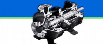
- ball-type valve assemblies, the closing elements of which are the seat and the ball;
- anchor shoes used to secure plug-in type sucker rod pumps in tubing pipes (when installing such elements, it is necessary to ensure that the suction cavity of the pump is sealed from the discharge cavity).
Of course, a mandatory element of the design of a sucker-rod pump is a rod - a round rod made of steel with upset ends. The main purpose of the rods, which can have different diameters (12, 16, 18, 22 and 25 mm), is to impart reciprocating movement to the plunger.
Sucker rod and coupling
Since the rods experience serious loads during the operation of a deep-well pump, high-quality steels are used for their production, and after production they are subjected to normal annealing and high-frequency hardening.
Rod pumping devices, depending on the design features of the plunger and cylinder, as well as the location of their anchor shoe, can fall into one of 15 categories.
The photo shows a ball-type suction valve housed in a cylindrical body