Operating principle
Centrifugal pumps are one of the most common machines in the industry. In terms of quantity, they are second only to electric motors. Because Since electric motors are used to drive pumps, it can be said that the lion's share of the world's electricity is spent on transporting liquids by centrifugal pumps.
Centrifugal pumps get their name from the way in which energy is transferred to the fluid.
As liquid is introduced to the pump, it comes into contact with the rotating impeller and is forced into the discharge pipe by centrifugal force through a specially shaped cavity called a spiral casing . All centrifugal pumps operate on this principle, but there may be design differences among them.
The pump transfers kinetic energy to the fluid . Kinetic energy refers to the speed of the fluid . Speed is only half the equation.
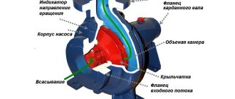
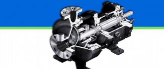
Fig. 1 – Centrifugal pump
The liquid enters the pump through the center of the wheel through the suction port. The friction between the fluid particles and the impeller causes the fluid to rotate. For example, how friction between the road and the rubber of a tire makes a car move.
The impeller pulls the fluid particles so they rotate when they come into contact with them. The fluid is pushed out of the wheel by centrifugal force - a phenomenon that pushes any object away from the center of the circle towards its borders. This is how the fluid receives kinetic energy from the wheel.
Therefore these pumps are called centrifugal .
The amount of energy transferred to a fluid depends on three factors:
- liquid density:
- impeller rotation speed:
- impeller diameter:
After the impeller, the liquid enters the cavity of the volute housing, from where it enters the pressure pipe.
Pressure . The pump must also produce positive pressure to meet the system requirements. Usually this is overcoming gravity when lifting liquid from a lower level to a higher one, and the frictional resistance of pipelines.
Simply put, pressure is the ability to complete a task . And the speed of the fluid is how quickly it will be completed.
Pumps must convert dynamic pressure into static pressure.
As the fluid passes through the spiral casing, it slows down as the passage area increases, because the productivity or the amount of fluid pumped over time depends on two factors: the first is the speed of the fluid, the second is the size of the cavity through which it moves .
If the flow is constant, then an increase in the flow area leads to a decrease in speed and an increase in pressure . Upon reaching the pressure port, most of the kinetic energy is converted into pressure.
By the way, read this article too: Blackmer Vane Pumps
If the speed drops, the pressure increases.
Main characteristics of centrifugal pumps
To choose the right pump for supplying water to a private house from a well or solving another problem, you need to consider not only the numbers given in the documentation for the device. However, for a general acquaintance with the parameters that are useful for the correct formulation of the problem, it is reasonable to provide the characteristics of devices for pumping liquids.
- Performance or delivery. This figure characterizes the amount of liquid that the pump ejects from the outlet pipe when the engine develops rated power.
- Pressure is the difference in pressure between the inlet and outlet pipes.
- Pressure-flow characteristic of a centrifugal pump - this graph shows the relationship between pressure and installation performance, allowing you to empirically analyze the sufficiency of supply on individual floors.
- The suction lift shows the depth from which the pump is capable of drawing water.
- Nominal pressure is an indicator at which the pump in the water supply network can operate in constant mode.
There are a number of parameters that are useful for professional analysis and design of a water supply network, for example, a private home. In practice, simplified methods are often used. An approximate pump selection diagram looks like this.
- An average statistical calculation of consumption is made. To do this, existing water selection devices are analyzed and their indicators are summed up. In two or more storey buildings, the total consumption figure is determined, and the volumes of water necessary to ensure the comfort of each floor are allocated.
- The nature of the water extraction zone is determined. For the well, the depth is taken into account, the installation location of the pump is analyzed (height from the ground surface).
- The altitude parameters of the water supply network are recorded. This is done for two or more storey buildings.
Based on these parameters, you can already select a suitable pump with sufficient accuracy. The nature of the intake location will determine what suction height the device should have. Based on the number of floors (height of liquid rise), a calculation is made and a model is selected based on the pressure characteristics.
The most important part of the analysis is the pressure-flow characteristic; it will show whether the pump is capable of supplying water in volumes for comfortable use to the floors above the first. The procedure is as follows:
- For the floor, the pressure drop (lift footage) is calculated;
- there is a point on the graph corresponding to the reduced indicator;
- The supply volume is determined according to the schedule.
If the resulting figure is greater than the required volume for a specific floor, the pump will cope with the task. Otherwise, you need a more productive or powerful device.
But even with careful consideration of all the features of the water collection point and distribution network, errors occur. Their reason is the lack of consideration of the hydraulic resistance of the pipeline structure, the dependence of the extraction and pressure indicators, and the analysis of the corresponding characteristics of the pumps. But this is a level of design that is beyond the reach of average users.
Advice! To create a certain technological buffer, it is recommended to select a pump with a margin of 20% in terms of key characteristics, primarily pressure.
Design
A pump is a machine that converts mechanical energy into kinetic energy, pumping fluid and electrically transporting it from one point to another.
A centrifugal pump consists of two main components.
- The first is a rotating disk with curved blades. It is called an impeller .
- The second is a specially shaped pipe called a volute casing , which contains the impeller and transport fluid .
There are 5 design elements that may vary:
- type of wheel;
- type of bearing;
- housing location;
- engine mount;
- number of steps.
Advantages
The widespread use of centrifugal devices is explained by a number of undeniable operational advantages, including:
- Ensuring stable supply and constant pressure of liquid under constant conditions.
- Light weight and compactness, which allows for economical use of production space.
- Simplicity of the device, easy operation and maintenance.
- High suction rates.
- The ability to pump dirty liquid that contains mechanical particles.
- Acceptable price.
Frame
It is made in the shape of a spiral with a decreasing radius, similar to a snail shell. The cavity of this body does not remain the same throughout. The flow area increases as you approach the pressure pipe.
Where the volute casing ends and the discharge pipe begins there is a protruding wedge called a cutwater .
It physically separates the volute housing from the discharge port and ensures that fluid leaves the pump rather than simply spinning around in the volute housing.
The flared part of the volute casing is very important, because with the help of it the pump creates pressure.
Working wheel
There are 3 types of impellers:
- open,
- semi-closed
- closed
The simplest design is the open wheel, which consists of razor-sharp blades evenly spaced on a hub.
Open wheel
The large, unrestricted fluid supply allows this type of wheel to transport fluids containing dirt, dust, sediment, and solids , making them ideal for waste pumps.
It is used in water treatment plants where wastewater is pumped to treat coarse sludge with solid impurities. Therefore, it has cutting blades at the front of the wheel to cut very large impurities.
If the blades are placed on the back plate, then such a wheel is called semi-closed .
Semi-closed wheel
If the blades are between two plates, then it is called closed .
Closed wheel
Closed wheels are more efficient than semi-closed and open wheels. Because the fluid flow follows a strictly defined path. This means that more fluid comes out of the pump and less simply circulates inside the wheel.
Their disadvantage is that they can easily become contaminated with debris.
A very popular misconception is that swirling blades help push fluid. But that's not really what they're designed for.
The purpose of the blades is to guide the liquid along the smoothest path. Backward-twisted blades help stabilize fluid flow conditions at high speeds and reduce engine load.
By the way, read this article too: How a radial piston pump works
The correct direction of rotation for this wheel is counterclockwise . Therefore, by the direction of the bends of the blades, we can tell the direction of movement of the wheel.
Shaft and bearings
Whatever type of wheel is used, it is mounted on a rotating shaft. The shaft must be secured in the housing with bearings in one of 2 ways:
- Console
- Symmetrical
Cantilever fastening
When the shaft is cantilevered, the impeller is fixed at one end and the bearings at the other.
This design places the suction and discharge ports perpendicular to each other, and the suction port directly in front of the center of the wheel.
Such pumps are called end suction pumps. They are widely used because they are cheap and easy to produce, but they have one drawback related to the path of fluid movement.
During pump operation, a low pressure zone is created in the suction port.
There is a high-pressure zone at the outlet of the wheel, from which the energized fluid enters the spiral casing.
Fluid flows towards the rear plate in open and semi-open wheels, which completely destroys the pressure balance. As a result, an axial force or load occurs - pushing the wheel towards the suction hole.
This can be compensated for by installing stronger bearings or drilling holes in the wheel plate to equalize the pressures. But these are not effective methods.
Symmetrical mounting
A more effective solution is to place the shaft on bearings on both sides. This is called symmetrical design .
Shaft support is improved not only by the placement of bearings on both sides, but also by the ability to use symmetrical closed wheels with double suction.
Since there are the same high and low pressure zones on both sides of the wheel, this successfully eliminates loading forces due to the balance of pressures. This design also has another advantage. The suction and discharge ports are located parallel to each other on opposite sides of the pump, and the housing is axially divided.
By simply unscrewing the bolts and removing the cover, the service technician can access the rotating part of the pump inside without removing the entire pump from the system.
Due to the separate axial design, pumps with a symmetrical bearing arrangement are called split-casing .
All of these, of course, are very good reasons to install such a pump in your mine right now. But there are some disadvantages. Because maintenance operations and sealing requirements are more complex for split casing pumps than for end suction pumps. They are also more expensive.
By the way, read this article too: Axial piston pump
Recommendations for installing centrifugal pumps
Correct installation of a centrifugal pump is the key to its stable operation, durability, and compliance with the service periods declared by the manufacturer. But attentiveness and adherence to standards ensures not only this. Installed in accordance with the manufacturer’s recommendations and the requirements of industry standards, the unit will eliminate such undesirable phenomena as excessive noise, vibration and associated deterioration of connection parameters, wear, and will also eliminate the occurrence of various abnormal and emergency operating modes.
Centrifugal pumps are installed in accordance with their parameters according to the following rules.
- The axis of the engine and turbine block must be placed horizontally, unless otherwise stated by the manufacturer and is not determined by the design features of the pump.
- For installations with direct connection to a pipeline break, with a power of up to 1 kW, installation with mounting on a wall, floor surface or other supporting structure is allowed.
- Pumps with a power of up to 10 kW must be mounted on a metal support frame fixed to the surface of the ground, floor, or power structure. It is allowed to install damping rubber gaskets between the support points and the corresponding areas of the centrifugal unit structure.
- Devices with a power of more than 10 kW must be installed on a frame attached to a concrete foundation pad. The dimensions of the latter must exceed the dimensions of the pump housing or console by 100 mm in all directions.
- When installing the pump, there must be at least half a meter from the extreme point of the electric motor block to the nearest wall or fencing element.
- Thermal insulation of the drive unit and motor is not allowed unless this is declared by the manufacturer’s instructions for specific operating conditions.
Important! Before connecting the pump to the pipeline system, you should manually check the operation of the device by disconnecting it from the power supply: rotate the shaft and turbine without a protective casing. Also, all inlet and outlet hoses and pipes must be flushed.
The installation and connection of the pipeline network must also comply with certain rules.
- The inlet and outlet pipes must fit freely to the corresponding connection points so that upon completion of installation they do not create stress on the pump structure.
- When connecting the ends of the pipeline, the flanges must be parallel; it is not permissible to apply significant forces to place them; when connecting between the surfaces of the contact elements, gaskets are installed (their nature depends on the type of working fluid).
- The centrifugal blower must be installed so that the desired direction of liquid pumping corresponds to the arrow on the device body.
- A pressure gauge must be installed at the pump outlet.
- A mechanical filter at the inlet of the installation, if its installation does not contradict the nature of the use of the pump, is required.
- The inlet and outlet pipes are equipped with shut-off valves.
- To ensure the possibility of draining the system, after the outlet pipe, a shut-off valve with a drainage outlet is installed at the lowest point of the pipeline network.
A separate set of rules applies to complex structures, piping systems with several installed pumps. The simplest of them refers to the installation of two blowers at one point, in parallel, to create an intense fluid flow. In this case, each pump is equipped with a check valve on the outlet pipe.
Centrifugal pump installation diagram
The average consumer who buys a centrifugal-type device for household needs can be given a couple of pieces of advice. When installing, you must strictly follow the equipment manufacturer's instructions. If it is recommended to install the pump on a flat horizontal surface, do not think that we are talking only about the position of the axes, and the unit can be mounted on a wall. This can disrupt the operation of safety devices, cause increased wear of components, and reduce the performance of the installation.
Advice! Do not ignore recommendations for permissible operating temperatures. The centrifugal pump is used only when the thermometer readings are positive. In winter, the unit must be moved indoors. Ignoring this rule will inevitably lead to equipment failure.
Shaft location
Centrifugal pumps are usually located horizontally . But sometimes vertically .
Vertical pumps are used to reduce installation space. You can find them at the bottom of a well or well, connected by a long, long shaft with a motor on top. This brings us to the motor connection. Usually electric.
Where to order?
Industrial centrifugal pumps experience high loads during their operation, so their service life is an important indicator of the efficiency of the manufacturing industry. When choosing such a device, you should trust only trusted and experienced manufacturers.
is a reliable representative on the Russian market of pumping equipment and offers to familiarize yourself with the products of its production.
Due to the high quality and reasonable price of pumps, there is a growing trend of steady demand for the company's products - users highly value the opportunity to purchase first-class equipment that fully meets the tasks of industrial processes and at the same time meets cost expectations. That is why pumping equipment is considered an excellent alternative to expensive units.
A competent formulation of the requirements for centrifugal equipment determines the choice of one or another type of pump, which makes it possible to provide a reliable solution along with a reduction in the cost of equipment.
Shaft connection type
There are 2 ways to transfer rotation from the motor to the pump: through a coupling or directly .
If the pump and motor are two separate machines, then they must be connected by a coupling.
Coupling connection
Couplings come in different shapes, sizes and designs. And one common requirement for them is to ensure the correct integrity of the shafts, otherwise without them, ensuring integrity would be a very sophisticated process.
To facilitate and maintain integrity, the engine and pump are mounted on a common support - a base plate.
Or, in the case of vertical installations, the engine is located on the frame.
This type of connection between the motor and the pump is called coupling. For large powerful installations and pumps with a dismountable casing, connection via a coupling is the only possible option.
The second connection method is direct. The engine and pump are located on a common shaft with a wheel located in a cantilever on the other side of the engine shaft. In this case, the installation does not require a coupling or complex procedures to maintain integrity.
However, because the motor and pump are located on the same shaft, supported only by the motor bearings, this method is only suitable for small and medium-sized end suction pumps.
Common failures of centrifugal pumps and methods for eliminating them.
A centrifugal pump is a fairly simple piece of equipment. Some faults will require the intervention of specialists who will carry out the necessary repairs. But a certain list of abnormal operating conditions or problems can be eliminated yourself.
- If the pressure decreases, you should check the inlet pipe. If coarse filters are installed on it, carry out preventive maintenance. It will not be superfluous to remove plaque on the walls of the incoming circuit pipeline.
- The reduction in pressure is eliminated on pumps equipped with an engine speed controller. The control pressure gauge is used to determine the fluid pressure at the outlet; if it does not correspond to the nominal value, the drive speed increases.
- Increased noise, shaft beating, and vibration directly indicate the need to replace seals or service bearings. This may also indicate loose connections on the housing. Before tightening, be sure to turn off the device and allow the engine to cool.
- The appearance of leaks and the flow of liquid from taps under high pressure indicates that the pump is exceeding the needs of the system. The supply is reduced by installing control valves at the inlet or a hydraulic accumulator with a sensor at the outlet.
- Stopping the water supply is most often due to air getting into the system. This may indicate either a lack of liquid at the inlet or an excess of the nominal cavitation height. In this case, you need to carefully check the condition of the water source.
- Excessive heat generation is a signal that it is time to carry out prevention. Inspect the bearings, check the tightness of the seals, replace the lubricant, clean the contact and terminal elements.
It’s worth noting right away: with careful, attentive installation that complies with the general rules and manufacturer’s recommendations, malfunctions of centrifugal pumps rarely bother the owners of such units.
However, no one is immune from surprises. Therefore, it is wise to carry out periodic equipment inspections and preventive maintenance.
Number of steps
A pump is classified by the number of stages it has. Most pumps have one stage with one impeller and one volute casing. However, some pumps have additional stages connected in series to increase pressure.
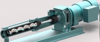
Multistage pump rotor
The idea is that one wheel imparts energy to the fluid and then directs it to the next wheel, which adds more energy to the fluid and then directs it to the next wheel, and so on, until eventually the fluid enters the discharge pipe.
Areas of application
In addition to versatility, centrifugal pumping equipment has a number of other advantages, such as:
- absence of pulsations when supplying water to the pipeline, which are characteristic, for example, of piston pumping equipment;
- affordable price;
- high reliability;
- ease of use and maintenance, which can be done with your own hands, without the involvement of third-party specialists.
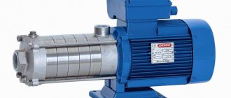
Centrifugal surface pump in a summer irrigation system
If we talk about the use of water centrifugal pumps in the domestic sphere, then it is quite wide. Most often, household centrifugal pumps are used to solve the following problems.
- With the help of such hydraulic machines, water is supplied to the autonomous water supply system of a private house or cottage from a well or borehole. Pumps used for this purpose can handle liquids that contain very small amounts of insoluble solids.
- By means of centrifugal pumps, water is pumped out from a well, borehole, ground reservoir, natural or artificial reservoir and supplied under a certain pressure to the irrigation system of a personal plot.
- Such equipment is also used to ensure constant circulation of coolant in autonomous heating systems of country houses and cottages. The use of special models of centrifugal pumps as an element of the heating system can significantly increase the efficiency of its operation, as well as reduce energy costs (gas, electricity and fuel for the boiler). Household centrifugal pumps used in heating systems can be equipped with one or two rotors with special blades.
- To pump water from basements and cellars, remove accumulated liquid from the territory of a personal plot, clean wells from silt deposits, drain septic tanks and sewage pits, special centrifugal pumps are also needed. They belong to a certain type - drainage hydraulic machines. Centrifugal-type fecal pumps are used to equip sewer systems, where they are used to pump out heavily contaminated liquid media.
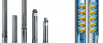
Submersible centrifugal pump in a well water supply system
The efficiency and ease of use of a centrifugal pump can be increased if it is equipped with additional technical devices, which, in particular, include:
- coarse filters that prevent solid inclusions contained in a liquid medium from entering the internal part of the device;
- a check valve that will prevent the pumped liquid from going back to the pumping source;
- float switch, with which the operation of the centrifugal pump can be switched to automatic mode;
- liquid level sensors;
- signaling devices and protection of the drive motor from overheating.