To quickly search for a steel grade and its yield strength, press Ctrl+F
.
Important! The yield strength of a particular grade of steel can vary depending on the type of heat treatment and temperature. If accurate information about the yield strength of steel is needed, it can be found in the accompanying documentation for a specific composition, grade or alloy.
| Brand | Yield strength, MPa |
| Steel St0 | 190 |
| Steel St1 | 190 |
| Steel St2 | 220 |
| Steel StZ | 240 |
| Steel St4 | 260 |
| Steel St5 | 280 |
| Steel St6 | 310 |
‘);> //–>
‘);> //–>
| Steel 08 | 200 |
| Steel 10 | 210 |
| Steel 15 | 230 |
| Steel 20 | 250 |
| Steel 25 | 280 |
| Steel 30 | 300 |
| Steel 35 | 320 |
| Steel 40 | 340 |
| Steel 45 | 360 |
| Steel 50 | 380 |
| Steel 20G | 280 |
| Steel Z0G | 320 |
| Steel 40G | 360 |
| Steel 50G | 400 |
| Steel 65G | 440 |
| Steel 10G2 | 250 |
| Steel 09G2S | 350 |
| Steel 10HSND | 400 |
| Steel 20Х | 300 |
| Steel 30Х | 320 |
| Steel 40Х | 330 |
| Steel 45Х | 350 |
| Steel 50Х | 350 |
| Steel 35G2 | 370 |
| Steel 40G2 | 390 |
| Steel 45G2 | 410 |
| Steel 33ХС | 300 |
| Steel 38ХС | 750 |
| Steel 18ХГТ | 430 |
| Steel 30ХГТ | 1050 |
| Steel 20KhGNR | 1200 |
| Steel 40HFA | 750 |
| Steel 30ХМ | 750 |
| Steel 35ХМ | 850 |
| Steel 40ХН | 400 |
| Steel 12ХН2 | 600 |
| Steel 12ХНЗА | 700 |
| Steel 20Х2Н4А | 450 |
| Steel 20KhGSA | 650 |
| Steel 30ХГС | 360 |
| Steel 30HGSA | 850 |
| Steel 38Х210 | 700 |
| Steel 50HFA | 1100 |
| Steel 60S2 | 1200 |
| Steel 60S2A | 1400 |
| Steel ШХ15 | 380 |
| Steel 20L | 215 |
| Steel 25L | 235 |
| Steel 30L | 255 |
| Steel 35L | 275 |
| Steel 45L | 315 |
| Steel 50L | 335 |
| Steel 20GYA | 275 |
| Steel 35GL | 295 |
| Steel 30GSL | 345 |
| Steel 40ХЛ | 490 |
| Steel 35HGSL | 345 |
| Steel 35ХМЛ | 390 |
| Steel 12Х13 | 350 |
| Steel 12Х14Н14В2М | 260 |
| Steel X23N13 | 295 |
| Steel X23N18 | 200 |
| Steel 12Х18Н10Т | 200 |
| Steel 08Х18Н10Т | 210 |
This page provides a detailed table of the yield strengths of various steel grades. The table is periodically updated with new data.
The meaning of some concepts and definitions used in this article is given separately.
The geometric characteristics of the body under consideration, equilibrium equations and the method of sections make it possible to determine the value of stresses at any point of the section under consideration. Accordingly, the essence of the strength calculation comes down to the fact that the stress σ at the most loaded point (on a certain elementary area) should be less than or equal to the resistance of the material:
σ ≤ R (318.1)
The resistance of a material, designated by the letter “R,” is the ability of a material to withstand loads applied to a body without destroying the material. Meanwhile, the resistance of a particular material depends on many different factors, the theoretical justification and consideration of which is a rather difficult task. In this regard, the resistance of various materials is determined experimentally.
Stress diagrams
Today, there are several methods for testing material samples. At the same time, one of the simplest and most revealing tests are tensile (tensile) tests, which make it possible to determine the proportionality limit, yield strength, elastic modulus and other important characteristics of the material. Since the most important characteristic of the stressed state of a material is deformation, determining the deformation value for known dimensions of the sample and the loads acting on the sample makes it possible to establish the above characteristics of the material.
Here the question may arise: why can’t we simply determine the resistance of a material? The fact is that absolutely elastic materials, which collapse only after overcoming a certain limit - resistance, exist only in theory. In reality, most materials have both elastic and plastic properties; we will consider what these properties are below using the example of metals.
Tensile tests of metals are carried out in accordance with GOST 1497-84. For this purpose, standard samples are used. The test procedure looks something like this: a static load is applied to the sample, the absolute elongation of the sample Δl is determined, then the load is increased by a certain step value and the absolute elongation of the sample is determined again, and so on. Based on the data obtained, a graph of elongation versus load is constructed. This graph is called a stress diagram.
Figure 318.1 . Stress diagram for a steel sample.
In this diagram we see 5 characteristic points:
Proportionality limit Рп (point A)
Normal stresses in the cross section of the sample when the proportionality limit is reached will be equal to:
The proportionality limit limits the area of elastic deformations on the diagram. In this section, the deformations are directly proportional to the stresses, which is expressed by Hooke’s law:
Рп = kΔl (318.2.2)
where k is the stiffness coefficient:
k = EF/l (318.2.3)
where l is the sample length, F is the cross-sectional area, E is Young’s modulus.
Pipe yield strength
The most obvious influence of this value is during the construction of pipelines for high-pressure systems. In such structures, special steel should be used, which has sufficiently large yield strengths, as well as minimal gaps between this parameter and the tensile strength. The higher the steel limit, the higher, naturally, the permissible operating voltage should be. This fact has a direct impact on the strength of steel, and accordingly, the entire structure as a whole. Due to the fact that the parameter of the permissible design value of the stress system has a direct impact on the required value of the wall thickness in the pipes used, it is important to calculate as accurately as possible the strength characteristics of the steel that will be used in the manufacture of pipes. One of the most authentic methods for determining these parameters is to conduct research on a discontinuous sample. In all cases, it is necessary to take into account the difference between the values of the indicator under consideration, on the one hand, and the permissible stress values, on the other.
In addition, you should know that the yield strength of a metal is always established as a result of detailed repeated measurements. But the system of permissible stresses is overwhelmingly adopted based on standards or generally as a result of technical specifications, as well as based on the personal experience of the manufacturer. In main pipeline systems, the entire regulatory collection is described in SNiP II-45-75. So, setting the safety factor is a rather complex and very important practical task. The correct determination of this parameter entirely depends on the accuracy of the calculated values of stress, load, and the yield strength of the material.
When choosing thermal insulation for pipeline systems, they also rely on this indicator. This is due to the fact that these materials directly come into contact with the metal base of the pipe, and, accordingly, can take part in electrochemical processes that adversely affect the condition of the pipeline.
Elastic moduli
The main characteristics of the elastic properties of materials are Young's modulus E (modulus of elasticity of the first kind, modulus of elasticity in tension), modulus of elasticity of the second kind G (modulus of elasticity in shear) and Poisson's ratio μ (transverse deformation coefficient).
Young's modulus E shows the ratio of normal stresses to relative strains within the limits of proportionality
Young's modulus is also determined empirically when testing standard tensile specimens. Since the normal stresses in the material are equal to the force divided by the initial cross-sectional area:
σ = Р/Fо (318.3.1), (317.2)
and relative elongation ε – the ratio of absolute deformation to the initial length
then Young’s modulus according to Hooke’s law can be expressed as follows
Figure 318.2 . Stress diagrams of some metal alloys
Poisson's ratio μ shows the ratio of transverse to longitudinal strains
Under the influence of loads, not only does the length of the sample increase, but also the area of the cross-section under consideration decreases (if we assume that the volume of material in the region of elastic deformation remains constant, then an increase in the length of the sample leads to a decrease in the cross-sectional area). For a sample having a circular cross-section, the change in cross-sectional area can be expressed as follows:
Then Poisson's ratio can be expressed by the following equation:
The shear modulus G shows the ratio of tangential stresses t to the shear angle
The shear modulus G can be determined experimentally by testing specimens for torsion.
During angular deformations, the section under consideration does not move linearly, but at a certain angle—the shear angle γ to the initial section. Since the shear stress is equal to the force divided by the area in the plane in which the force acts:
t = P/F (318.3.6)
and the tangent of the angle of inclination can be expressed as the ratio of the absolute deformation Δl to the distance h from the place where the absolute deformation was recorded to the point relative to which the rotation was made:
tgγ = Δl/h (318.3.7)
then at small values of the shear angle the shear modulus can be expressed by the following equation:
G = m/γ = Ph/FΔl (318.3.8)
Young's modulus, shear modulus and Poisson's ratio are related to each other by the following relationship:
E = 2(1 + μ)G (318.3.9)
The values of the constants E, G and µ are given in table 318.1
Table 318.1 . Approximate values of the elastic characteristics of some materials
Note: Elastic moduli are constant values, however, manufacturing technologies for various building materials change and more accurate values of elastic moduli should be clarified according to currently valid regulatory documents. The modulus of elasticity of concrete depends on the class of concrete and therefore is not given here.
Elastic characteristics are determined for various materials within the limits of elastic deformations limited on the stress diagram by point A. Meanwhile, several more points can be identified on the stress diagram:
What is proof strength?
Let's figure out what this parameter is. In cases where the voltage diagram does not have pronounced areas, it is necessary to determine a conditional DC. So this is the stress value at which the relative permanent strain is 0.2 percent. To calculate it on the stress diagram along the axis of determination ε, it is necessary to set aside a value equal to 0.2. From this point a straight line is drawn parallel to the initial section. As a result, the point of intersection of the straight line with the line of the diagram determines the value of the conditional yield strength for a particular material. This parameter is also called technical PT. In addition, the conditional yield limits for torsion and bending are distinguished separately.
Work of deformation
The greater the internal forces of interaction between the particles of the material, the higher the strength of the material. Therefore, the value of elongation resistance per unit volume of a material can serve as a characteristic of its strength. In this case, the tensile strength is not an exhaustive characteristic of the strength properties of a given material, since it characterizes only the cross sections. When a rupture occurs, the interconnections are destroyed over the entire cross-sectional area, and during shears, which occur during any plastic deformation, only local interconnections are destroyed. To destroy these connections, a certain amount of work of internal interaction forces is expended, which is equal to the work of external forces expended on displacement:
A = РΔl/2 (318.4.1)
where 1/2 is the result of the static action of the load, increasing from 0 to P at the time of its application (average value (0 + P)/2)
During elastic deformation, the work of forces is determined by the area of the triangle OAB (see Fig. 318.1). Total work expended on the deformation of the sample and its destruction:
A = ηРmaxΔlmax (318.4.2)
where η is the coefficient of completeness of the diagram, equal to the ratio of the area of the entire diagram, limited by the curve AM and straight lines OA, MN and ON, to the area of a rectangle with sides 0Рmax (along the P axis) and Δlmax (dotted line in Fig. 318.1). In this case, it is necessary to subtract the work determined by the area of the triangle MNL (related to elastic deformations).
The work spent on plastic deformation and destruction of the sample is one of the important characteristics of the material that determines the degree of its fragility.
Popular types of concrete
There are ordinary or heavy concrete (M25-M800) and light concrete (M10-M200). Let's take a closer look at them.
Lungs
From M5 to M35 are used for non-load-bearing structures - they are not particularly strong. M50 and M75 are suitable for preparatory work before pouring concrete. M100-M150 – for low-rise construction, structures, lintels.
M200-M300 are used for most construction tasks. M200 corresponds to class B15, its strength is 196 kgf/m2 or 15 MPa. M250 (B20) has an average strength of 262 kgf/cm2 or can withstand a pressure of 20 MPa, like the above brand, it gains 70% of its strength after 28 days, and the remaining 30% within six months. These are lightweight concretes. Screeds, floors, blind areas, foundations, stairs, supports, curbs are most often made from it. It freezes at sub-zero temperatures and loses up to 5% of its resistance when defrosted.
Lightweight concrete can be checked by hitting it with a hammer or rubbing it with a sharp object - quite distinct marks will remain on the surface.
Regular
M350 (class B25) - a cubic meter of this concrete can withstand a load of 25 MPa, it corresponds to M250. M400 (class B30) - withstands a load of 30 MPa. These grades and higher are used for multi-storey buildings, load-bearing, monolithic structures, swimming pool bowls. Most often used for road surfaces and floor slabs, as it is waterproof (class W8), frost-resistant (F200).
Grades from M350 (classes from B25) and more relate to more durable concrete, they have a high density and better resistance to frost and humidity, but are much heavier.
Tensile strength
— mechanical stress σ B > , above which material destruction occurs. In other words, this is a threshold value, exceeding which mechanical stress will destroy a certain body made of a specific material. It is necessary to distinguish between static and dynamic strength limits. There is also a distinction between compressive and tensile strength limits.
Compression strain
Compressive deformations are similar to tensile deformations: first, elastic deformations occur, to which plastic deformations are added beyond the elastic limit. The nature of deformation and fracture during compression is shown in Fig. 318.5:
Figure 318.5
a – for plastic materials; b – for brittle materials; c – for wood along the grain, d – for wood across the grain.
Compression tests are less convenient for determining the mechanical properties of plastic materials due to the difficulty of recording the moment of failure. Methods of mechanical testing of metals are regulated by GOST 25.503-97. When testing for compression, the shape of the sample and its dimensions may be different. Approximate values of tensile strength for various materials are given in tables 318.2 - 318.5.
If the material is under load at a constant stress, then additional elastic deformation is gradually added to the almost instantaneous elastic deformation. When the load is completely removed, the elastic deformation decreases in proportion to the decreasing stresses, and the additional elastic deformation disappears more slowly.
The resulting additional elastic deformation under constant stress, which does not disappear immediately after unloading, is called elastic aftereffect.
Parameter classification
The material has temporary resistance in response to impacts of various types, so the characteristic is classified into several groups. Forces to which the workpiece or structural element is subjected:
- Stretching. The product is pulled by the edges using a special machine.
- Torsion. The object is placed in conditions under which the rotating shaft operates.
- Bend. The workpiece is bent and unbent in several directions.
- Compression. The material is pressed alternately from different sides.
For the same material, the PP may vary. An example is steel. It is used more often than other alloys because steel structures have proven to be the strongest, most durable, and most resistant to the elements. At the same time, they are reliable and do not emit harmful substances into the atmosphere.
There are several grades of steel. They are produced using different technologies, and depending on this, the characteristics of the workpieces and structures differ. For conventional brands, the PP is 300 MPa. As the carbon content increases, the strength increases. The hardest grades have a value of 900 MPa. Factors on which strength characteristics depend:
- the amount of useful and undesirable impurities;
- method of heat treatment (cryotreatment, hardening, annealing).
SAMPLING METHODS
1. SAMPLING METHODS
(Changed edition, Amendment No. 2).
1.2. Before testing, it is permissible to straighten the sample by applying gentle pressure on it or by light blows of a hammer on the sample lying on the support. The backing and hammer should be of a softer material than the sample.
The inadmissibility of straightening samples must be stipulated in the normative and technical documentation for reinforcing steel.
where is the mass of the test sample, kg;
– length of the test sample, m;
– steel density, 7850 kg/m.
1.5. For turned and round samples of reinforcement with a nominal diameter from 3.0 to 40.0 mm, the cross-sectional area is determined by measuring the diameter along the length of the sample in three sections: in the middle and at the ends of the working length; in each section in two mutually perpendicular directions. The cross-sectional area of the sample is calculated as the arithmetic mean of these six measurements.
1.6. The cross-sectional area of a rope is defined as the sum of the cross-sectional areas of the individual wires that make up the rope.
It is allowed to use the nominal cross-sectional area of the ropes specified in the regulatory and technical documentation for the ropes.
(Changed edition, Amendment No. 1).
1.7. The initial estimated length is measured with an error of no more than 0.5 mm.
1.8. The diameters of round and turned reinforcement samples with a nominal diameter of 3.0 to 40.0 mm are measured with a caliper according to GOST 166 or a micrometer according to GOST 6507.
1.9. The mass of test samples of periodic profile reinforcement with a nominal diameter of less than 10 mm is determined with an error of no more than 1.0 g, samples of reinforcement with a diameter from 10 to 20 mm - with an error of no more than 2.0 g, and samples with a diameter of more than 20 mm - with an error of no more 1% by weight of the sample.
Samples of reinforcing steel are weighed on scales in accordance with GOST 29329*, and the length of the sample is measured with a metal ruler in accordance with GOST 427. _______________ * The document is not valid on the territory of the Russian Federation. GOST R 53228-2008 is valid. – Note from the database manufacturer.
Ways to increase strength characteristics
There are several ways to do this, two main ones:
- addition of impurities;
- heat treatment, for example, hardening.
Sometimes they are used together.
General information about steels
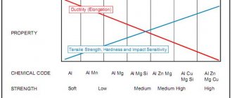
All of them have chemical and mechanical properties. Below we’ll talk in more detail about ways to increase strength, but first, let’s present a diagram showing all the varieties:
Also watch a more detailed video:
All of them have chemical and mechanical properties. Below we’ll talk in more detail about ways to increase strength, but first, let’s present a diagram showing all the varieties:
Carbon
The higher the carbon content of a substance, the higher the hardness and the lower the ductility. But the composition should not contain more than 1% of the chemical component, since a larger amount leads to the opposite effect.
Manganese
A very useful additive, but with a mass fraction of no more than two percent. Mn is usually added to improve machinability. The material becomes more susceptible to forging and welding. This is due to the displacement of oxygen and sulfur.
Silicon
Effectively increases strength characteristics without affecting ductility. The maximum content is 0.6%, sometimes 0.1% is enough. Combines well with other impurities; together, they can increase corrosion resistance.
Alloying Additives
You can also find the following impurities:
- Chrome – increases hardness.
- Molybdenum – protects against rust.
- Vanadium – for elasticity.
- Nickel – has a good effect on hardenability, but can lead to brittleness.
These and other chemicals must be used in strict proportions according to the formulas. In the article we talked about tensile strength (short-term resistance) - what it is and how to work with it. They also gave several tables that you can use while working. To finish, let's watch the video:
To clarify the information you are interested in, please contact our managers by phone;;. They will answer all your questions.
EQUIPMENT
2.1. Machines of all systems are used provided they comply with the requirements of this standard and GOST 1497.
2.2. When conducting tests, the following requirements must be met:
reliable sample centering;
smoothness of loading;
the average loading rate when testing to the yield strength should not be more than 10 N/mm (1 kgf/mm) per second; beyond the yield point, the loading speed can be increased so that the speed of movement of the movable gripper of the machine does not exceed 0.1 of the working length of the test sample per minute; the scale of the force meter of the testing machine should not exceed five times the expected value of the highest load for the test sample of reinforcement;
the design of the grips of the testing machine must exclude the possibility of rotation of the ends of the rope around the axis of the sample.
2.3. Measuring instruments must comply with the requirements of this standard and other technical documentation.
Classification by purpose
The classification of steel types by purpose has already been given above. Marking of structural steels includes the following designations:
- Construction - denoted by the letter C and numbers characterizing the yield strength.
- Bearing - designated by the letter Ш. Next comes the designation and content of alloying additives, mainly chromium.
- Instrumental unalloyed - denoted by the letter U and carbon content in tenths of a percent.
- High-speed - denoted by the letter P and symbols of alloying components.
- Unalloyed structural steel has the symbols Cn and a number indicating the carbon content in tenths or hundredths of a percent.
Classification of steel by purpose
The remaining varieties, including tool grades made of alloy steels, do not have special designations other than their chemical composition, so the decoding and purpose of individual types can only be determined from reference literature.