Varieties of oxygen-converter method
In oxygen converters, smelting technology occurs in one of two well-known ways. They bear the name of their creators: Thomas and Bessemer. However, modern technologies have stepped far forward. Thus, the nitrogen content in Thomas and Bessemer steel is three times higher than in converter or open-hearth steel.
The difference between them lies in the implementation of technological solutions and the refractory material used. In the Thomas process it is quite difficult to control the flow of melting periods. The Bessemer process allows air to be blown through the bottom of the converter itself.
According to the method of organizing the purge, the oxygen-converter process can be: with top, bottom or bottom, combined purge.
The first method provides the best conditions for the following technological processes: supplying oxygen to the converter for purging, more efficient removal of excess gas accumulations, convenient pouring of liquid cast iron, additional loading of scrap metal and other additional materials.
Bottom purge converters are always made with a smaller volume compared to top purge converters. To implement blowing through the bottom, from seven to twenty special devices called tuyeres are installed in the lower part of the converter. Their number depends on the volume of the converter. These devices are mounted in that part of the bottom that rises above the level of molten metal at the moment the converter is tilted. After emptying the contents, the purging stage occurs. The speed of movement of carbon molecules to the surface increases significantly. This reduces the total content of the chemical element in the melt. Thus, it becomes possible to produce steel in which the percentage of remaining carbon is very small.
In addition to carbon, it is possible to obtain better sulfur removal. By blowing from the bottom, it is possible to increase the amount of metal produced by 2%.
The latter method allows you to combine some of the advantages of both methods and at the same time eliminate some of the existing disadvantages. Blowing with a powerful flow of oxygen is carried out from top to bottom. Blowing is carried out from bottom to top with an inert gas, for example argon. Nitrogen is sometimes used instead of inert gases to reduce overall cost. The use of combined blowing allows you to achieve the following positive indicators:
- increase the volume of metal smelted;
- the percentage of added scrap metal can be increased;
- achieve a significant reduction in the required ferroalloys;
- reduce the required amount of oxygen for purge;
- reduce the content of various gas impurities, which improves the quality of steel.
Wider challenge
It may seem that you can select a set of optimal loading modes for production nodes once and stick to it.
Unfortunately, this would only work if we could produce roughly the same set of steels - or if we were doing very long runs on large orders. In practice, flexibility in our production area means some losses in the optimality of the process, but these losses are much less than the gain due to the flexibility of production as a whole. Simply put, every day we need to cast different orders - several different steels, each of which has its own process and its own “soup recipe”.
Orders arrive in approximately two to three weeks at a higher level system, where they are clustered, grouped, defragmented and sent down to the shop floor in the form of daily plans.
Based on the orders selected for execution on a given day, the head of the planning department draws up a daily task for loading UNRS, something like the following: “from 12 to 15 on such and such a machine we bottle such and such a series, readjust for 2 hours, then from 17 to 22 we bottle the next batch, readjust it, then from midnight to 4 am the third.” For each of the five different installations, several episodes of varying lengths can be scheduled. In addition to the series on UNRS, he needs to schedule the operation of converters. This task, in fact, requires calculation, especially in the case of a large number of diverse orders. But until now it was solved manually using the experience and professional instinct of a specialist. Now he has the opportunity to create several scenarios, combining different launch times of different series and trying combinations. The best plan received is sent to work.
After the shift manager draws up such a high-level plan for the day, he goes to the workshop dispatch service, where the shift manager draws up a more detailed plan, taking into account all intermediate units. Previously, again, a specialist manually calculated such plans. More precisely, in fact, of course, this process was automated, but still the automation systems did not have the ability to recalculate the schedule in real time depending on the position and status of each bucket, that is, it was compiled once or twice per shift. Now we have made a system that can constantly recalculate optimal schedules. When the situation goes beyond the plan, it is recalculated.
So, there is an order book that specifies the orders that production must deliver. Some of the orders from this book fall into a specific shift, where they are tactically optimized within the production area. Each order is a series of pourings. We go from the casting to the converters and prescribe what will happen at what time and at what installation, and how the ladles will get there. This is done by the head of the production planning department.
There are shifts when the sequences are very long, and the section works along the same route all day. This is a relief for everyone and makes things easier. But more often the brands have become different.
The planning system in its current implementation works on the basis that pig iron comes to us in the required quantity and at the moments when the converters need to be loaded. There are also nuances with this, but the inclusion of technical processes from previous stages has been left in development for now; this is a separate and complex issue.
Some slab sizes and steel grades can only be cast in specific (not all) installations. Some series must be completed at the end of the shift, since they will be continued by the next shift.
Oxygen converter technology
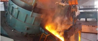
The design of an oxygen converter is quite simple. In terms of its external shape, the converter looks like a large vessel. It ends at the top with a tapering neck. This shape of the upper part makes it possible to provide favorable conditions for organizing the upper blowing system. All components are loaded into the converter from above. The principle of operation of an oxygen converter is as follows: molten cast iron is poured into it (it serves as fuel for the oxygen converter), scrap metal is poured into it, and additional materials are loaded. In the central part of the metal body of the converter there is a rotation mechanism. With its help, the converter is tilted to drain the finished steel. Converters with a volume exceeding 200 tons use a powerful two-way drive. For this purpose, four powerful electric motors are used, two on each side.
Oxygen converter method
When choosing the size of the upper neck, take into account that it is advisable to load the starting material, for example, scrap steel, not in parts, but at once the entire volume. This allows you to reduce the total time required for the entire technological process. However, as the size of the convector neck increases, the overall heat loss begins to increase. There is an increase in nitrogen content. This occurs due to the spontaneous absorption of additional oxygen from the surrounding air through the wide neck. Nitrogen also comes in with oxygen. This additional nitrogen dissolves in the metal and causes a decrease in quality.
In many countries, the most common are converters with a volume of 20 tons to 450 tons. The duration of the converter steelmaking process does not exceed 50 minutes.
Maintaining the reliability of chemical reactions during the converter steelmaking process occurs by maintaining a temperature of more than 1400°C. To ensure these conditions, the metal body of the converter is lined inside with refractory material (usually a special fireclay or refractory brick). At the first stage, the oxygen converter is loaded. After this, oxygen supply begins. The required amount of supplied air to provide one melt is 350 cubic meters.
Oxygen enters into a chemical reaction with molten cast iron at high speed. This allows excess carbon to be removed. The sulfur and phosphorus present in the metal are simultaneously converted into slag. This technological chain makes it possible to stop smelting at the moment when the level of carbon content reaches the specified technical conditions. This makes it possible to obtain a fairly large range of carbon steels and achieve a low content of sulfur, phosphorus and other impurities.
Monitoring of ongoing processes and the quality of the metal is carried out by periodic sampling. They make it possible to determine the degree of carbon gas remaining in the melt. When the percentage of carbon content reaches a predetermined level, the oxygen purging process is stopped. Upon completion of the technological chain, the steel is poured into a special ladle. The remaining slag is removed through a special drain in the converter.
Particular attention is paid to controlling the amount and rate of oxygen supply. The percentage of oxygen content is regulated by introducing coolants into the converter. The functions of coolers can be performed by: scrap metal, iron ore, limestone.
Oxygen converter circuit
All the same, a certain percentage of oxygen is always retained in the finished steel. It enters into an oxidation reaction with iron. In this way, iron oxide is formed. To reduce the content of this oxide (to carry out the operation of iron reduction), so-called deoxidizers are added to the ladle. If the process of so-called deoxidation occurred technologically correctly, as a result of cooling there is no process of gas evolution. Metallurgists call this steel calm. To produce such steel, ferromanganese-based additives are first added to the melt as deoxidizers. At the final stage, ferrosilicon is added. At the end of the melt - ordinary aluminum.
The entire technological chain of steel production is divided into the following stages:
- oxidation of additives present;
- successive chemical reactions (first oxidation of silicon; then manganese, and finally carbon);
- dephosphorization;
- desulfurization;
- slag formation;
- process of general deoxidation.
If all the oxygen has not been removed, the formation of iron oxide continues. In addition, when cooling, the chemical reaction between carbon and iron continues. It leads to the release of carbon monoxide. Its intensive formation and subsequent release from the melt is clearly visible visually. The process is reminiscent of boiling water in a kettle. In the language of professionals, such steel is called “boiling”. To eliminate this effect, ferromanganese is added to the melt.
The presence of dissolved gases in the liquid metal, which do not have time to escape, leads to the formation of voids. They seriously reduce the quality of the entire metal obtained. To prevent such formations, special degassing is carried out at the melting stage. To achieve the best effect, this operation is carried out in special vacuum chambers. In this way, it is possible to significantly increase the density and improve the physical and mechanical properties of the resulting batch of metal.
How the workshop works
I roughly described the idea of converter steel production above.
At the entrance we have cast iron, which is smelted in a blast furnace, and ferrous metal scrap. It arrives at the converter section still in liquid form and is poured into the converter (after the scrap is poured into it). The converter is quite well automated. Since the chemical composition of the raw material varies, it has sensors that allow it to roughly understand what is happening inside and select the correct temperature regime, oxidation regime, and so on. In the converter, the cast iron is blown with oxygen, which heats it to a temperature of 1600+ degrees Celsius, oxidizing silicon, manganese and carbon. The resulting oxides are removed from the melt, and the output is liquid metal in the volume of the ladle (smelting) - what will later become steel of a certain grade.
We have three converters; they can serve the “broth” at any time and according to a given schedule. Moreover, if the oxidation process is started, we cannot stop it; in any case, after about 40 minutes the output will be a ladle of melt, with which we will need to do something.
It looks like this:
And this is what a metal sample (cooled) looks like, which is taken from a ladle at an after-furnace processing unit. On the long handle with which this sample is taken, at the end there is a container shaped like this frozen sample. There is a rarefied environment, and liquid metal is sucked into this form, and the form itself burns.
In this photo, the bucket is moving around the workshop on an overhead crane. We have 10 taps, they are like this:
Overhead crane winch
Another logistics limitation is clearly visible here: the overhead crane can only move around the workshop on its guides only from one crane to another, and not completely independently. The cranes are controlled from the cabins:
So, you get a ladle of liquid metal. Next, it needs to be moved around the workshop so that, depending on the type of metal being produced, the melt is processed in one way or another - brought to the desired temperature, added impurities (fluxes and/or ferroalloys) and stirred for some time at a certain temperature.
The smaller the deviation of the actual process from the standard melt processing time, the less resources (in particular, electricity) need to be spent on production. Each ladle has a critical temperature (liquidus temperature), after decreasing to which the melt becomes unsuitable for further casting. In such a situation, the melt must be reheated. As we say, steel freezes. The best way to heat it up is to lower graphite electrodes into it and turn on the current (nothing is returned to the converter). There are only two stands with electrodes (ladle furnace installations). They are like this:
With a tight schedule, each unscheduled reheat means a wave of delays spreads further down the line. In addition, graphite electrodes themselves are quite expensive, and each such additional heating means an increase in the cost of the final product. That’s why our service works to prevent steel from freezing.
A steel pourer takes a metal sample at a ladle furnace installation.
There are 8 units in the converter shop, we move the ladle between them, often leaving them in them for N minutes. Between the converter, for example, in the degasser and at other units, the steel can spend 20 minutes, maybe 40 - it depends on the task (how exactly the melt needs to be processed in order to obtain the ordered steel grade) and the initial conditions.
Transfer of insulating backfill
At the end of the workshop, the steel enters one of the UNRS - a continuous steel casting installation.
This is a top view of one of our UNRS. We see two stands for installing steel ladles. The steel from the ladle on the left, which has a lid, has almost spilled; in a couple of minutes there will only be slag left there. The ladle on the right has just been placed by a crane, it is full, its pouring will begin as soon as the steel in the left ladle runs out. As already mentioned, it is extremely important that the flow of steel into the UNRS is not interrupted
Metal finishing installation
The key word is “continuous”: these installations must be fed ladles of properly prepared “soup” without stopping. Let me remind you that if we form a line in front of the UNRS, the steel in the buckets cools down, so everything needs to be done exactly on time. We can vary the pouring speed, but within small limits.
Here is a schematic diagram of the workshop:
At this stage, it may seem that the task comes down to forming optimal queues for the workshop units and reheating what does not fit into these queues. The workshop is constantly solving the problem of how to optimally produce steel from converters and process it on various units in order to withstand all series at UNRS.
Aluminum wire for steel deoxidation
Advantages and disadvantages of the oxygen-converter method
The main advantages of the method include:
- Compared to other smelting processes, it has higher productivity;
- the design diagram of the oxygen converter itself is quite simple (an ordinary metal tank, that is, a housing inside which there is a refractory material);
- low cost of refractories;
- low cost of the resulting steel;
- low capital costs for construction, even taking into account the added cost of building oxygen stations.
Experience in operating converters has shown that the economic efficiency exceeds the open-hearth method by 14%, and the electric melting method by 25%.
The most obvious disadvantages include:
- the need to load only liquid cast iron into the converter. The addition and subsequent processing of metal recyclables is possible only in small quantities (no more than 10%);
- At the stage of technological purging, a fairly large amount of useful iron burns out along with carbon. Technological losses can reach 15%;
- Difficulties arise in organizing a system for monitoring and regulating the converter steel smelting process. This is due to the high speed of chemical processes;
- insufficient control does not allow obtaining steel with precisely specified technical characteristics.
Scope of application of converter steel types
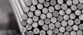
The existing disadvantages somewhat limit the scope of application of such steel. It is used to produce parts that do not have high technical requirements. Oxygen converters produce three types of products: carbon, alloy and low-alloy steel. These grades are used for the production of wire (rod rod), small diameter pipes, and certain types of rails.
Special products are actively used in construction. Almost all so-called automatic steel is manufactured using converter technology. A large number of hardware products are produced from it: bolts, nuts, screws, self-tapping screws, staples, and so on.

