When constructing power plants, petrochemical plants, gas pipelines and other facilities with welded pipeline joints, standards require the preparation of working documentation. This is done for comprehensive control over the quality of work and the compliance of the constructed facility with design requirements.
An important tool for such control is the diagram of welded joints. It shows a schematic view of the facility’s pipelines, equipment, shut-off and control valves and connecting welds. Next to each connection is information related to it.
What it is?
The as-built diagram is an integral element of the design and working documentation of water supply, heat supply, transport pipelines and technological installations with liquid or gaseous media. It is not to scale and gives only a general idea of the relative position of the welds in space. The drawing is necessarily linked to geodetic coordinates or to an object with known coordinates.
When forming a document, the order of the seams on a particular section of the pipeline is observed. The document is a guide to welding work, a planning and control tool. It is issued together with a summary table of joints, summarizing the data on joints in tabular form. In addition to the technical parameters of the seams, personal data of the welders and the number of their personal mark are given.
Decor
The document is drawn up by the organization conducting the installation work . It is compiled by the production and technical department on the basis of design and working documentation transferred to installers from the customer or directly from the designer, if provided for by the contract.
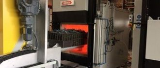
Based on the 3D model of the object presented by the designer, the technical department begins the formation of a weld pattern.
Simultaneously with drawing up the scheme, other related documents are also prepared:
- summary table of joints;
- acts of welders performing test welds and assigning them a personal mark;
- certificates of welding work.
Without a complete set of documents, the facility cannot be accepted for operation
Signature
The layout of the welded joints of the pipeline must be certified by the signatures of the following officials:
- foreman directly responsible for performing welding work at the site;
- head of production and technical department;
- Chief Engineer;
- welders who performed the work, indicating the number of their personal mark.
It is also necessary to coordinate with it all deviations from design parameters encountered as a result of monitoring, such as dimensions and slopes. A certified record of the absence of deviations or their agreement is made on the form. If there are many deviations, they can be agreed upon in a separate act. Then the document contains a link to the number and date of this document
Pivot table
The document is drawn up according to the unified form P27.4, approved by Order of the Ministry of Energy No. 197. It must contain a complete list of seams welded at the facility.
The pivot table contains information about all connections of an object in a form convenient for control, generalization and analysis.
The following data is provided for each connection:
- serial number,
- the name of the node to which it belongs;
- type of steel alloy from which the pipes are made;
- their diameter and wall thickness;
- quantity;
- number corresponding to the designation on the Diagram.
If additional seams were welded on the site, their number and number are given in the additions column . This table allows you to determine the total number of joints, group them by diameter, wall thickness, and the need for non-destructive testing. This makes it easier to plan labor intensity, the need for consumables, as well as instrumental quality control of connections.
Design rules
The pipeline welding diagram must contain the following information:
- Object name;
- pipeline class;
- pipe parameters: alloy material, diameter and wall thickness;
- transportable medium;
- snapping to reference points.
Each joint on the diagram must have its own unique number . Sometimes continuous numbering of welded joints throughout the entire project is used, then the designation takes the form “E12.123”, where before the dot there is an object identifier, and after the actual joint number on a specific diagram.
The stage of forming a diagram of welded joints from a 3D model. The drawing is simplified, fittings and equipment are replaced with symbols.
In addition, the diagram can indicate the distance between adjacent joints and supporting objects, such as turns, reinforcement, supporting metal structures or process equipment. This is mandatory in two cases:
- the pipeline is covered with a layer of insulation;
- the site runs underground or is hidden in the walls.
If necessary, markings (for example, in the event of an accident, planned repair or inspection) will help you quickly and without unnecessary costs and damage to structures find the joint in the event of repairs, without resorting to additional documentation.
Joints in a schematic drawing can be of two types:
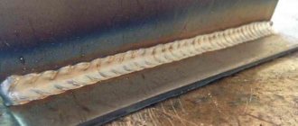
Rotary welds include welds made by a welder with a section of pipe rotated along the longitudinal axis at a certain angle . Usually this is an angle that is a multiple of 90°. Such seams are welded in the “bottom” position. Such seams are of higher quality and more durable, since the work is carried out in a position convenient for welding. Analysis of statistical data shows that the frequency of detection of defects in such seams is significantly lower than in non-rotating ones. welded joints.
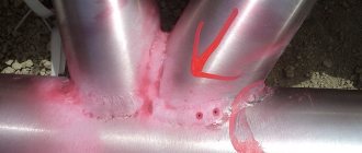
Defects in welded joints
1 - undercut; 2 - no gain; 3 - excessive gain; 4 - porosity; 5 - slag inclusions; 6 - external crack; 7 - internal crack; 8 - lack of penetration of the root of the seam; 9 — lateral lack of penetration; 10 - burn-through
Hidden defects in welds are revealed by physical testing methods (transmission). Hidden defects include lack of root penetration, lateral lack of penetration, burn-through, and internal cracks. The most dangerous defects are cracks, lack of penetration of the root of the seam, and lack of lateral penetration of the seam.
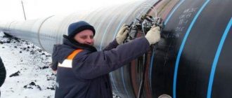
Welders who have passed the appropriate exam and have special certificates are allowed to carry out welding work on gas pipelines. Each welder is assigned a code, which he places at a distance of 50 mm from the welded joints. The quality of welding work is periodically monitored.
For each section of the gas pipeline under construction, a welding diagram is drawn up, which indicates the name of the object, the number of the joint, the distance between the joints, the welder’s code, the binding of the joints at characteristic points, the joints tested by physical methods, as well as the places where the joints are cut for mechanical tests.
In addition to welded joints, gas pipelines use detachable joints, which are used in places where disconnecting devices, compensators, pressure regulators, instrumentation and other fittings are installed.
Connecting parts and parts of gas pipelines and gas equipment include bends, tees, transitions, flanges, plugs, couplings, locknuts, bends, etc.
Bends are bent and welded. Bent ones are made from seamless pipes with a diameter of up to 400 mm. Welded bends are manufactured for gas pipelines with a diameter of more than 150 mm. It is preferable to use bent elbows, since they have fewer welded joints and create little resistance to gas flow.
Tees or crosses are used to install branches from a gas pipeline in one or two directions. They can be pass-through or transitional. Transitions are used in cases where it is necessary to change the diameter of the gas pipeline.
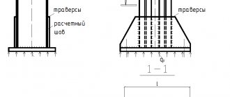
Flange connections are the most common type of connection to pipelines for shut-off, control valves, filters and other equipment. The following types of steel flanges are distinguished (figure below): flat welded, butt welded, loose on a welded ring, loose on a flanged pipe. Butt-welded flanges for connection to the pipe have a cut edge for welding. Loose flanges are not welded to the pipes, but rest on a welded ring or collar of a flanged pipe. The flanges are secured with bolts, the number of which depends on the diameter of the pipes being connected.
Designations of joints in the diagram
The joints in the diagram are indicated in accordance with the state standard GOST 2.312-72 “Conventional images and designations of seams of welded joints”, with a solid main line.
The following inscription is made in the form of a fraction on the take-out:
- numerator - joint number;
- denominator is the number of the welder’s personal mark.
A personal mark is issued for each welder separately . During certification, he welds a test seam that matches the material, diameter and thickness of the pipes with the actual connections on site. Such tests are carried out in special certification centers, the number of the personal mark is approved by order of the installation company.
Sample form
All forms are filled out in accordance with the requirements of the standard. Below is a welding form for the pipeline (sample) .
The document is at the final stage of formation. Contains the necessary joint data, corner stamp and additional information. A summary table is visible above the stamp.
The diagram of welded joints is an important document that describes the relative position of the joints and their most important parameters . It is issued for any facility that has pipelines with welded seams. The diagram and the summary table compiled with it serve as a means of planning installation work, recording execution and quality control.
When constructing power plants, petrochemical plants, gas pipelines and other facilities with welded pipeline joints, standards require the preparation of working documentation. This is done for comprehensive control over the quality of work and the compliance of the constructed facility with design requirements.
An important tool for such control is the diagram of welded joints. It shows a schematic view of the facility’s pipelines, equipment, shut-off and control valves and connecting welds. Next to each connection is information related to it.
Sealing materials.
According to OST, flat gaskets made of paronite, rubber, metal, cardboard, fluoroplastic brand “Ftoroplast-4” and composite materials based on them should be used to seal the flange connections of the fittings with the gas pipeline and the cover with the housing.
To seal threaded connections, it is recommended to use combed flax strands impregnated with a special gas lubricant, fluoroplastic tapes of the “Ftoroplast-4” brand and other sealing materials that ensure the tightness of the connection.
When operating valves with stuffing box, special attention should be paid to the packing material - dimensions, correct placement in the stuffing box.
The height of the stuffing box must be such that the ground box in the initial position enters the stuffing box by no more than 1/6 of its height, but not less than 5 mm. As a packing material for seals of shut-off valves, the most effective is the use of fluoroplastic sealing material of the FUM-V brand.
Re-stuffing of gas fittings is permitted at a pressure in the gas pipeline of no more than 0.01 MPa. Replacement of gaskets of flange connections of valves and gas pipelines can be done at a pressure of not lower than 40 and not higher than 200 daPa.
Polyethylene pipes. The introduction of polyethylene pipes is one of the current trends in increasing the efficiency of capital construction and reducing its material and labor intensity.
Experience in the construction and operation of polyethylene gas pipelines has revealed the following advantages of polyethylene pipes:
- reducing the cost of construction and installation work and increasing the pace of construction;
- no need for insulation work or construction of systems for protecting gas pipelines from corrosion;
- the physical and chemical properties of polyethylene ensure durability, tightness and high stability throughout the entire life of gas pipelines;
- increased throughput due to the smooth inner surface;
- moving polyethylene pipes during installation does not require a large number of workers and lifting mechanisms.
Thus, thanks to the properties of polyethylene materials, the reliability of gas pipelines increases and their service life increases.
Pipes are produced in accordance with GOST R 50838-95 “Polyethylene pipes for gas pipelines. Technical Specifications”, which provides technical requirements and basic operational characteristics, pipe range, test methods, requirements for polymer materials and other product characteristics. Taking into account domestic experience in pipe production, amendment No. 3 of this standard has been put into effect since 2005, which makes it possible to expand the range of manufactured pipes both in terms of the range and types of polyethylene used for the manufacture of pipes, and to increase the pressure in gas pipelines. The production of polyethylene pipes and connecting parts for gas pipelines is under the control of Rostechnadzor of Russia and is carried out only with its permission or license. The table below shows the main parameters of polyethylene pipes for gas pipelines.
What it is?
The executive diagram is an integral element of the design and working documentation of water supply, heat supply, transport pipelines and technological installations with liquid or gaseous media. It is not to scale and gives only a general idea of the relative position of the welds in space. The drawing is necessarily linked to geodetic coordinates or to an object with known coordinates.
When forming a document, the order of the seams on a particular section of the pipeline is observed. The document is a guide to welding work, a planning and control tool. It is issued together with a summary table of joints, summarizing the data on joints in tabular form. In addition to the technical parameters of the seams, personal data of the welders and the number of their personal mark are given.
Decor
The document is drawn up by the organization conducting the installation work . It is compiled by the production and technical department on the basis of design and working documentation transferred to installers from the customer or directly from the designer, if provided for by the contract.
Based on the 3D model of the object presented by the designer, the technical department begins the formation of a weld pattern.
Simultaneously with drawing up the scheme, other related documents are also prepared:
- summary table of joints,
- acts of welders performing test welds and assigning them a personal mark,
- certificates of welding work.
Without a complete set of documents, the facility cannot be accepted for operation
Metal pipes and connecting parts.
At the initial stage of development of the gas industry, cast iron pipes were used for the construction of gas pipelines.
As scientific and technological progress developed, steel pipes replaced cast iron pipes, and steel pipes were replaced by polyethylene pipes. Currently, both metal and polyethylene pipes are in use. Metal pipes are made from easily weldable low-alloy and low-carbon steels. The maximum carbon content in steel should not exceed 0.25, sulfur - no more than 0.05, phosphorus - no more than 0.46%. These requirements are largely satisfied by mild open hearth steels. When choosing steel pipes for gas pipelines, they are guided by the current “Instructions for the use of steel pipes for the construction of gas supply systems.”
Signature
The layout of the welded joints of the pipeline must be certified by the signatures of the following officials:
- foreman directly responsible for performing welding work at the site,
- head of production and technical department,
- Chief Engineer,
- welders who performed the work, indicating the number of their personal mark.
The completed and certified document must be agreed upon with the design organization.
It is also necessary to coordinate with it all deviations from design parameters encountered as a result of monitoring, such as dimensions and slopes. A certified record of the absence of deviations or their agreement is made on the form. If there are many deviations, they can be agreed upon in a separate act. Then the document contains a link to the number and date of this document
Pivot table
The document is drawn up according to the unified form P27.4, approved by Order of the Ministry of Energy No. 197. It must contain a complete list of seams welded at the facility.
The pivot table contains information about all connections of an object in a form convenient for control, generalization and analysis.
The following data is provided for each connection:
- serial number,
- the name of the node to which it belongs,
- type of steel alloy from which the pipes are made,
- their diameter and wall thickness,
- quantity,
- number corresponding to the designation on the Diagram.
If additional seams were welded on the site, their number and number are given in the additions column . This table allows you to determine the total number of joints, group them by diameter, wall thickness, and the need for non-destructive testing. This makes it easier to plan labor intensity, the need for consumables, as well as instrumental quality control of connections.
Main parameters of polyethylene pipes
| Nominal outer diameter, d, mm | Estimated weight of 1 m of pipes, kg | ||||
| SDR 17.6 | SDR17 | SDR 13.6 | SDR11 | SDR9 | |
| 20 | – | – | – | 0,132 | 0,162 |
| 25 | – | – | – | 0,169 | 0,210 |
| 32 | – | – | 0,229 | 0,277 | 0,325 |
| 40 | 0,281 | 0,292 | 0,353 | 0,427 | 0,507 |
| 50 | 0,436 | 0,449 | 0,545 | 0,663 | 0,790 |
| 63 | 0,682 | 0,715 | 0,869 | 1,05 | 1,25 |
| 75 | 0,970 | 1,01 | 1,23 | 1,46 | 1,76 |
| 90 | 1,40 | 1,45 | 1,76 | 2,12 | 2,54 |
| 110 | 2,07 | 2,16 | 2,61 | 3,14 | 3,78 |
| 125 | 2,66 | 2,75 | 3,37 | 4,08 | 4,87 |
| 140 | 3,33 | 3,46 | 4,22 | 5,08 | 6,12 |
| 160 | 4,35 | 4,51 | 5,50 | 6,67 | 7,97 |
| 180 | 5,52 | 5,71 | 6,98 | 8,43 | 10,1 |
| 200 | 6,78 | 7,04 | 8,56 | 10,4 | 12,5 |
| 225 | 8,58 | 8,94 | 10,9 | 13,2 | 15,8 |
| 250 | 10,6 | 11,0 | 13,4 | 16,2 | 19,4 |
| 280 | 13,2 | 13,8 | 16,8 | 20,3 | 24,4 |
| 315 | 16,7 | 17,4 | 21,3 | 25,7 | 30,8 |
| Notes: Standard Dimensional Ratio (SDR) is the ratio of the nominal outside diameter of a pipe d to the nominal wall thickness e. | |||||
The minimum average outside diameter corresponds to the nominal outside diameter.
Polyethylene pipes are manufactured in straight sections, coils and on coils, and pipes with a diameter of 200 mm or more are made only in straight sections. Pipes with a diameter of up to 225 mm, produced in lengths, are bundled into packages weighing up to 3 tons and fastened in several places.
The symbol for polyethylene pipes consists of the word “pipe”, the abbreviated name of the material PE80, PE100, the word “GAS”, the standard dimensional ratio SDR, a dash, nominal diameter, pipe wall thickness and the designation of the current standard for polyethylene pipes. For example, a pipe made of polyethylene PE80, SDR 17.6, with a nominal diameter of 180 mm and a nominal wall thickness of 10 mm will have the following symbol: Pipe PE80 GAS SDR 17.6-180×10 GOST R 50838-95.
Polyethylene pipes must have markings that are applied to their surface using heat embossing with coloring of the applied embossing, color printing or another method that does not degrade the quality of the pipe. The marking includes the company's trademark, pipe designation, month and year of manufacture. Coils, coils, packages and block packages are supplied with a label with transport markings.
Pipes must have a safety factor of at least 2.5. If gas pipelines are laid in areas with a seismic activity level of more than 7 points or in areas of permafrost, then pipes with a safety factor of at least 2.8 must be used, and welded butt joints must undergo 100% control by physical methods.
When using pipes with a safety factor of at least 2.8, it is permitted to lay polyethylene gas pipelines with pressures exceeding 0.3 to 0.6 MPa in settlements with predominantly one- and two-story residential buildings. In the territory of small rural settlements, it is permitted to lay polyethylene gas pipelines with a pressure of up to 0.6 MPa with a safety factor of at least 2.5, and the laying depth must be at least 0.8 m to the top of the pipe.
Before installation of polyethylene gas pipelines, the following preparatory work must be completed:
- layout and planning of the gas pipeline route;
- excavation; selection of polyethylene pipes;
- transportation of pipes to the place of installation in a trench; laying out pipes along the route;
- installation of welding equipment.
Polyethylene gas pipelines are laid at a depth of at least 0.8 with a slope towards the condensate collector, while the rise should be no more than 5 cm per 1 m of the gas pipeline length.
When laying pipes in a trench under the pipes, make a bed of sand at least 10 cm thick and cover it with a 20 cm layer of sand, and then with local soil, if it is not sandy. It is allowed to lay two or more polyethylene gas pipelines in one trench, as well as polyethylene and steel gas pipelines. In this case, the distance between gas pipelines is taken taking into account the possibility of repair work. The requirements for the gap between polyethylene gas pipelines and other communications, as well as buildings, are regulated by SNiP.
Polyethylene pipes must have a standard dimensional ratio of the outer diameter of the pipe to the wall thickness (SDR) of no more than 11 with a safety factor of no less than 2.5 for transitions up to 25 m wide and no less than 2.8 in other cases. For polyethylene gas pipelines when they cross public railways and at the intersections of highways of the first and third categories, it is necessary to use polyethylene pipes with an SDR of no more than 11 and a safety factor of at least 2.8.
Connections of polyethylene pipes with steel pipes or fittings are made detachable (using flanges) or permanent. For pipes with a diameter of up to 50 mm, the use of polyethylene-steel connections with a threaded metal end is allowed.
Flanges are used for detachable connections of pipes, as well as for their connection with metal gas pipelines. The main elements for connecting polyethylene pipes are an O-ring and conical flanges (figure below). When tightened with bolts, the flanges move along the conical surface of the sealing ring and ensure a tight connection.
Design rules
The pipeline welding diagram must contain the following information:
- Object name,
- pipeline class,
- pipe parameters: alloy material, diameter and wall thickness,
- transportable medium,
- snapping to reference points.
Each joint on the diagram must have its own unique number . Sometimes continuous numbering of welded joints throughout the entire project is used, then the designation takes the form “E12.123”, where before the dot there is an object identifier, and after the actual joint number on a specific diagram.
The stage of forming a diagram of welded joints from a 3D model. The drawing is simplified, fittings and equipment are replaced with symbols.
In addition, the diagram can indicate the distance between adjacent joints and supporting objects, such as turns, reinforcement, supporting metal structures or process equipment. This is mandatory in two cases:
- the pipeline is covered with a layer of insulation,
- the site runs underground or is hidden in the walls.
If necessary, markings (for example, in the event of an accident, planned repair or inspection) will help you quickly and without unnecessary costs and damage to structures find the joint in the event of repairs, without resorting to additional documentation.
Joints in a schematic drawing can be of two types:
Rotary welds include welds made by a welder with a section of pipe rotated along the longitudinal axis at a certain angle . Usually this is an angle that is a multiple of 90°. Such seams are welded in the “bottom” position. Such seams are of higher quality and more durable, since the work is carried out in a position convenient for welding. Analysis of statistical data shows that the frequency of detection of defects in such seams is significantly lower than in non-rotating ones. welded joints.
A fixed joint is welded without rotating the pipe to a convenient position . On the contrary, the welder has to follow the seam around the pipeline, including in disadvantageous positions: seams with a positive and negative slope, as well as vertical and ceiling ones. In this case, it is necessary to change the inclination of the electrode, its speed, welding current and other important operating modes several times.
In this case, the seam is welded in several stages, which negatively affects its strength and durability. Working in such conditions requires a worker with extensive experience and high qualifications.
Near each joint, the details of the welders who welded it are indicated (full name, personnel number or personal mark number).
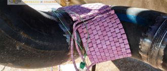
The document also notes connections for which quality control will be required by non-destructive means (ultrasound, x-ray, etc.). For particularly important objects associated with high pressures and temperatures, aggressive environments and other factors, control is carried out for all joints.
The location diagram of welded joints indicates the joints at which non-destructive testing (ultrasonic, radiographic) is required. All joints are subject to visual inspection.
When drawing up a document, the same coordinate system is used as in other design and working documentation.
Important! The schema data and the summary table must match the Work Log data in the following parameters:
- connection numbers,
- pipe parameters,
- Full name of welders and personal mark numbers
- duration of work.
If the dimensions and slopes of the constructed object correspond to the design values, the inscription is written on the diagram: “There are no deviations from the design parameters.” Otherwise, a designer's inscription coordinating these deviations or a link to a separate document - an act of approval - is required.
The diagram is included in the object passport , drawn up on high-quality media and using materials that guarantee long-term storage.
Steel flanges
a - flat welded; b - butt weld; c - free on the welded ring; g - free on a flanged pipe; d - on a welded ring and a rolled pipe; 1 - pipe; 2 - hole for bolt; 3 - flange; 4 - weld; 5 - welded ring; 6 - collar
The quality of flange connections is affected by the preparation of the sealing surfaces, therefore at least two sealing grooves are made on each flange. The tightness of flange connections is ensured by various gaskets 3-5 mm thick. In addition to paronite, oil and petrol resistant rubber, aluminum and copper are used.
Insulating flanges (figure below) are installed on gas pipelines to prevent the movement of stray currents from one part of the pipeline to another. In a flange connection, consisting of free flanges on welded rings, dielectric gaskets made of paronite, textolite, klingerite, etc. are installed. Textolite is placed between the welded rings, and insulating sleeves and washers are used to insulate the bolts.
Designations of joints in the diagram
The joints in the diagram are indicated in accordance with the state standard GOST 2.312-72 “Conventional images and designations of seams of welded joints”, with a solid main line.
The following inscription is made in the form of a fraction on the take-out:
- numerator - joint number,
- denominator is the number of the welder’s personal mark.
A personal mark is issued for each welder separately . During certification, he welds a test seam that matches the material, diameter and thickness of the pipes with the actual connections on site. Such tests are carried out in special certification centers, the number of the personal mark is approved by order of the installation company.
Insulating flange
1 - pipe wall; 2 - free flange; 3 - bolt with nut and washer; 4 — textolite bushing; 5 — textolite washer; 6 - welded ring; 7 - weld; 8 — textolite ring; 9 - Klingerite gaskets
Insulating connections are installed on the above-ground vertical sections of the inputs and outputs of the GRP and cabinet-mounted GRU (SHRP), as well as in front of the GRU to protect against stray currents. The most common insulating connections are flange connections IFST, IFS, SI, IS.
The figure below shows the design of an IFS type insulating connection, which is installed after the shut-off valve along the gas flow. In a flange connection, in addition to two main flanges welded to the ends of the gas pipeline being connected, there is a third flange, the thickness of which depends on the diameter of the gas pipeline. Between the flanges, for the purpose of their electrical insulation, paronite (vinyl plastic or fluoroplastic) gaskets coated with electrically insulating bakelite varnish are installed. The section of the fluoroplastic sleeve contains tightening pins, and between the nut washers and flanges there are also insulating gaskets made of paronite coated with bakelite varnish. Along the perimeter of the special flange there are threaded sockets into which screws are screwed in to check the electrical resistance between the main flanges and the special flange.
Sample form
All forms are filled out in accordance with the requirements of the standard. Below is a welding form for the pipeline (sample) .
The document is at the final stage of formation. Contains the necessary joint data, corner stamp and additional information. A summary table is visible above the stamp.
The diagram of welded joints is an important document that describes the relative position of the joints and their most important parameters . It is issued for any facility that has pipelines with welded seams. The diagram and the summary table compiled with it serve as a means of planning installation work, recording execution and quality control.
When preparing as-built documentation for welding, many are faced with the problem of how to properly prepare the documentation. The layout of welded joints is part of the welding documentation. Let's figure out how to correctly design the layout of welded joints?
The layout of welded joints is not to scale. Welded joints should be marked on the diagram. The distance between joints is indicated if the pipeline is subsequently insulated or underground. This is necessary to determine the location of the welded joint.
The joints in the diagram are indicated as rotary and non-rotary.
A rotary joint is a pipeline joint that is welded by rotating the pipe by 360˚, 180˚ or 90˚, and welding is usually performed in the lower position.
A rotary joint is easier to perform, since welding occurs in a comfortable position, which in turn indirectly affects the quality of welding. The likelihood of defects occurring is much less than when welding non-rotary joints.
A fixed joint is a pipeline joint, welding of which occurs without rotating the pipe, and the welder himself performs welding in various positions around the pipe.
A fixed joint is difficult to make. The main difficulty lies in the need to weld in different positions (bottom, vertical, ceiling seam). When welding in different positions, it is necessary to adjust the current strength. Welding a fixed joint requires high skill.
Before approval at the site, the welder must weld test and approval joints. The dimensions, design and position of the trial and acceptance joints must match the standard dimensions of production welded joints.
Also on the diagram of welded joints the number of the joint is indicated. The numerator indicates the serial number of the joint. The denominator indicates the personal mark of the welder.
The welder's mark is assigned upon passing certification at the NAKS certification center. To work at hazardous production facilities, the welder’s mark is assigned by order of the enterprise , in accordance with clause 8 of the Federal Tax Code.
The welder's mark is made in accordance with GOST 25726-83. On one side of the brand there is a mirrored alphabetic and numerical designation, on the other side there is a place for impact during branding.
Depending on the object on which welding is being carried out, the mark is located at a distance of 40mm - 60mm from the welded joint. When welding is performed by several welders, marks are placed at the boundaries of the joints.
Marking of welded joints is necessary to identify the welder who made the welded joint. If defects are detected in the welded joint, the contractor is determined by the applied mark and the issue of removing the welder from work and recertifying him, with passing practical and theoretical exams, is decided.
The diagram of the location of welded joints indicates the joints at which non-destructive testing (ultrasonic, radiographic) was performed. All joints are subject to visual inspection. For each hazardous production facility, the scope of control is determined according to the relevant regulatory documents.
A summary table of welded joints, carried out on the diagram, will allow you to determine the number of joints of different diameters and the required number of non-destructive testing.
The stamp for the location of welded joints is signed by the welding supervisor, the welders who performed the welding, and the installation supervisor.
The location diagram of welded joints indicates the name of the object, the group or class of the pipeline, the diameter and thickness of the pipeline wall, the working environment, connections to fixed supports, buildings, fittings, etc.
Important. The layout of welded joints must correspond to the welding work log. (Numbering of joints, marks, diameters, wall thickness, welding sequence, as well as welders).
Types of welded joints
a - welded V-shaped joint; b - welded joint with a cylindrical backing ring; c - welded joint with a shaped backing ring; 1 - gas pipeline; 2 - beveled edge of the pipe; 3 — blunting of the edge; 4 - welding tack; 5 - cylindrical backing ring; 6 — collar of the ring; 7 - shaped backing ring
If the welding technology is incorrect, the seam may have defects (picture below). Some defects are detected through external inspection. Such defects include undercut, excessive or small reinforcement of the seam, external crack, porosity and slagging of the seam.