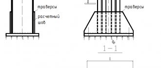
When constructing power plants, petrochemical plants, gas pipelines and other facilities with welded pipeline joints, standards require the preparation of working documentation. This is done for comprehensive control over the quality of work and the compliance of the constructed facility with design requirements.
An important tool for such control is the diagram of welded joints. It shows a schematic view of the facility’s pipelines, equipment, shut-off and control valves and connecting welds. Next to each connection is information related to it.
What it is?
The as-built diagram is an integral element of the design and working documentation of water supply, heat supply, transport pipelines and technological installations with liquid or gaseous media. It is not to scale and gives only a general idea of the relative position of the welds in space. The drawing is necessarily linked to geodetic coordinates or to an object with known coordinates.
When forming a document, the order of the seams on a particular section of the pipeline is observed. The document is a guide to welding work, a planning and control tool. It is issued together with a summary table of joints, summarizing the data on joints in tabular form. In addition to the technical parameters of the seams, personal data of the welders and the number of their personal mark are given.
The importance of certain distances between welds. Minimum values for welds
Fusion welding (manual arc, gas, semi-automatic and other types of welding) involves a large input of heat into the weld pool. As a result, the heat will spread to the metal located in the immediate vicinity of the weld pool - a heat-affected zone is formed. In this area, under the influence of high temperature, processes associated with changes in the structure of the metal also occur. This also leads to a decrease in the mechanical properties of the joint as a whole. Welding seams should be positioned so that the heat-affected zones do not overlap each other.
The minimum distance between two welds is regulated by the thickness of the pipeline parts being welded. For wall thickness less than 20 mm, the distance between welds must be at least 50 mm.
Another factor influencing the distance between welds is the fixtures used during assembly. The dimensions of the pipeline elements must be no less than the installation dimensions of the device.
The welds of pipelines laid on supports must be located at a distance from the edge of the support sufficient to control the welded joint, repair, and insulation.
When welding tee joints of pipes that have a longitudinal factory seam, it is necessary to ensure that it is located on the opposite part of the pipe perimeter.
When welding tee connections, taps, branches, deviations from the regulated dimensions are allowed if the following conditions are met: holes are drilled after heat treatment. These requirements must be specified in the design documentation for the product.
Decor
The document is drawn up by the organization conducting the installation work . It is compiled by the production and technical department on the basis of design and working documentation transferred to installers from the customer or directly from the designer, if provided for by the contract.
Based on the 3D model of the object presented by the designer, the technical department begins the formation of a weld pattern.
Simultaneously with drawing up the scheme, other related documents are also prepared:
- summary table of joints;
- acts of welders performing test welds and assigning them a personal mark;
- certificates of welding work.
Without a complete set of documents, the facility cannot be accepted for operation
Signature
The layout of the welded joints of the pipeline must be certified by the signatures of the following officials:
- foreman directly responsible for performing welding work at the site;
- head of production and technical department;
- Chief Engineer;
- welders who performed the work, indicating the number of their personal mark.
The completed and certified document must be agreed upon with the design organization.
It is also necessary to coordinate with it all deviations from design parameters encountered as a result of monitoring, such as dimensions and slopes. A certified record of the absence of deviations or their agreement is made on the form. If there are many deviations, they can be agreed upon in a separate act. Then the document contains a link to the number and date of this document
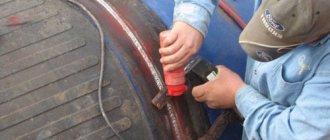
How can you set distances when welding pipelines?
The distance is set using special supports and pendants. If they are not available (we are talking about their models for certain types of pipes), they are developed for each specific type of pipe used in the pipeline, as well as for the pipelines themselves.
Suspensions can be flexible or rigid, depending on the installation conditions of the pipeline and the purposes of its further operation. Supports always have a rigid static character.
As for setting the distance while maintaining the diametrical arrangement of the pipes, centralizers are used, which are fixed to the edges of the pipes prepared for welding.
Pivot table
The document is drawn up according to the unified form P27.4, approved by Order of the Ministry of Energy No. 197. It must contain a complete list of seams welded at the facility.
The pivot table contains information about all connections of an object in a form convenient for control, generalization and analysis.
The following data is provided for each connection:
- serial number,
- the name of the node to which it belongs;
- type of steel alloy from which the pipes are made;
- their diameter and wall thickness;
- quantity;
- number corresponding to the designation on the Diagram.
If additional seams were welded on the site, their number and number are given in the additions column . This table allows you to determine the total number of joints, group them by diameter, wall thickness, and the need for non-destructive testing. This makes it easier to plan labor intensity, the need for consumables, as well as instrumental quality control of connections.
WELDED JOINTS AND THEIR LOCATION
2.3.1. All welded connections of pipelines (including seams of welded parts) must be located so that it is possible to control them using the methods provided for by the Rules and ND for the product.
2.3.2. To connect pipes and shaped parts, butt welding with full penetration should be used.
Corner welded joints are allowed for welding fittings, pipes, and flat flanges to pipelines. Corner joints must be made with full penetration.
Fillet welded joints with a structural gap (structural lack of penetration) are allowed for pipes and fittings with an internal diameter of 100 mm or less and flat flanges with a nominal pressure of no more than 2.5 MPa (25 kgf/cm2) and a temperature of no more than 350°C. Quality control of such connections must be carried out according to normative documents agreed upon in the prescribed manner.
Lap joints are allowed for welding linings that strengthen holes in pipelines of categories III and IV, stops, supports, hangers, insulation fastening elements, etc.
2.3.3. In butt welded joints of elements with different wall thicknesses, a smooth transition from a larger to a smaller section must be ensured by appropriate one-sided or two-sided machining of the end of the element with a thicker wall.
The angle of inclination of the transition surfaces should not exceed 15°.
If the difference in wall thickness is less than 30% of the wall thickness of the thin element, but not more than 5 mm, it is permissible to perform the specified smooth transition on the side of the opening of the edges due to the inclined location of the seam surface.
These provisions do not apply to welded joints with cast, forged and stamped parts, as well as with steeply curved elbows. The transition angles at the ends of such parts, as well as the angles of inclination of the surface of the seams, should not exceed the standards established by standards, specifications and instructions.
2.3.4. When welding pipes and other elements with longitudinal and spiral welds, the latter must be offset from one another. In this case, the displacement must be at least three times the wall thickness of the pipes (elements) being welded, but not less than 100 mm for pipes with an outer diameter of more than 100 mm.
2.3.5. For transverse butt welded joints that are not subject to ultrasonic testing or local heat treatment, the distance between the axes of adjacent welds on straight sections of the pipeline must be at least three times the wall thickness of the pipes (elements) being welded, but not less than 100 mm. The distance from the axis of the weld to the beginning of the rounding of the knee must be at least 100 mm.
2.3.6. For transverse butt welded joints subject to ultrasonic testing, the length of the free straight section of the pipe (element) in each direction from the axis of the seam (the nearest welded parts and elements, the beginning of the bend, the axis of the adjacent transverse seam, etc.) must be no less than the values given in table . 2:
table 2
| Nominal wall thickness of welded pipes (elements) S, mm | Minimum length of a free straight section of pipe (element) in each direction from the weld axis, mm |
| Up to 15 | |
| St. 15 to 30 | 5S +25 |
| St. 30 to 36 | |
| More than 36 | 4S +30 |
2.3.7. For transverse butt welded joints subject to local heat treatment, the length of the free straight section of the pipe (element) on each side from the axis of the seam (to the nearest welded parts and elements, the beginning of bending, the adjacent transverse seam, etc.) must be at least l
, determined by the formula:
,
but not less than 100 mm. Here Dm -
average diameter of the pipe (element) equal to
Dm
=
Da
-
S
;
Da
- nominal outer diameter, mm;
S
is the nominal wall thickness of the pipe (element), mm.
2.3.8. When installing steeply curved, stamped and stamped welded elbows, it is allowed to place transverse welded joints at the beginning of the rounding and weld the steeply curved elbows together without a straight section.
2.3.9. For corner welded connections of pipes and fittings with pipeline elements, the distance from the outer surface of the element to the beginning of pipe bending or to the axis of the transverse butt weld should be:
a) for pipes (fittings) with an outer diameter of up to 100 mm - not less than the outer diameter of the pipe, but not less than 50 mm;
b) for pipes (fittings) with an outer diameter of 100 mm and more - at least 100 mm.
2.3.10. The distance from the axis of the transverse welded joint of the pipeline to the edge of the support or hanger must be selected based on the possibility of carrying out the inspection, control and heat treatment provided for by the Rules (RD).
Design rules
The pipeline welding diagram must contain the following information:
- Object name;
- pipeline class;
- pipe parameters: alloy material, diameter and wall thickness;
- transportable medium;
- snapping to reference points.
Each joint on the diagram must have its own unique number . Sometimes continuous numbering of welded joints throughout the entire project is used, then the designation takes the form “E12.123”, where before the dot there is an object identifier, and after the actual joint number on a specific diagram.
The stage of forming a diagram of welded joints from a 3D model. The drawing is simplified, fittings and equipment are replaced with symbols.
In addition, the diagram can indicate the distance between adjacent joints and supporting objects, such as turns, reinforcement, supporting metal structures or process equipment. This is mandatory in two cases:
- the pipeline is covered with a layer of insulation;
- the site runs underground or is hidden in the walls.
If necessary, markings (for example, in the event of an accident, planned repair or inspection) will help you quickly and without unnecessary costs and damage to structures find the joint in the event of repairs, without resorting to additional documentation.
Joints in a schematic drawing can be of two types:
- rotary;
- non-rotating.
Rotary welds include welds made by a welder with a section of pipe rotated along the longitudinal axis at a certain angle . Usually this is an angle that is a multiple of 90°. Such seams are welded in the “bottom” position. Such seams are of higher quality and more durable, since the work is carried out in a position convenient for welding. Analysis of statistical data shows that the frequency of detection of defects in such seams is significantly lower than in non-rotating ones. welded joints.
A fixed joint is welded without rotating the pipe to a convenient position . On the contrary, the welder has to follow the seam around the pipeline, including in disadvantageous positions: seams with a positive and negative slope, as well as vertical and ceiling ones. In this case, it is necessary to change the inclination of the electrode, its speed, welding current and other important operating modes several times.
In this case, the seam is welded in several stages, which negatively affects its strength and durability. Working in such conditions requires a worker with extensive experience and high qualifications.
Near each joint, the details of the welders who welded it are indicated (full name, personnel number or personal mark number).
The document also notes connections for which quality control will be required by non-destructive means (ultrasound, x-ray, etc.). For particularly important objects associated with high pressures and temperatures, aggressive environments and other factors, control is carried out for all joints.
The location diagram of welded joints indicates the joints at which non-destructive testing (ultrasonic, radiographic) is required. All joints are subject to visual inspection.
When drawing up a document, the same coordinate system is used as in other design and working documentation.
Important! The schema data and the summary table must match the Work Log data in the following parameters:
- connection numbers;
- pipe parameters;
- Full name of welders and personal mark numbers
- duration of work.
If the dimensions and slopes of the constructed object correspond to the design values, the inscription is written on the diagram: “There are no deviations from the design parameters.” Otherwise, a designer's inscription coordinating these deviations or a link to a separate document - an act of approval - is required.
The diagram is included in the object passport , drawn up on high-quality media and using materials that guarantee long-term storage.
After completion of the work, all documentation is checked for completeness and correctness of execution and filling. After verification, the documents are handed over to the archive.
As-built documentation
As-built surveys, as-built plans, and drawings.
As-built surveys, diagrams for the construction of communication networks.
1 As-built survey of cable (telephone) sewerage, example, .
As-built surveys, plans for the construction of a gas network.
1 As-built survey of gas distribution network, example,
2 Executive profile of the pipeline position before repair,
3 Executive diagram of pipeline opening,
As-built surveys, schemes for the construction of sewerage and storm drainage systems.
1 As-built survey of storm drainage, example
2 As-built diagram - storm drainage layout, example
,
3 As-built diagram - development of trench soil for storm drainage, example
,
4 Executive diagram - installation of reinforced concrete trays for storm drainage, example,
5 As-built diagram of backfilling a storm drainage trench, example,
6 As-built diagram - arrangement of sand preparation for reinforced concrete storm drainage trays, example
,
7 Executive diagram of the planned position of the axis of the drainage collector, example
,
8 Executive diagram of the installation of seals for household sewerage outlets,
9 Executive diagram of the construction of a pit for a well,
10 Executive diagram of the installation of a trench for household sewerage,
11 Executive diagram of the construction of the base for the well,
12 Executive diagram of the foundation for the pipeline,
13 As-built diagram for the installation of a domestic sewage well,
14 Executive diagram plan and profile of household sewerage
,
15 Executive scheme for sealing the outlet of household sewerage,
16 As-built diagram of initial backfilling of the pipeline
,
17 As-built diagram of the final backfilling of the pipeline
,
18 Executive diagram. Profile of external household sewage system,
19 Executive diagram of a grease trap, example,
20 Executive diagram of laying sewerage and water supply pipes,
As-built surveys, diagrams for the construction of a power supply network.
1 Executive drawing of power supply and lighting networks,
2 Executive diagram of the grounding device,
3 Executive single-line diagram on stationary switches with a switch at the input, example,
4 Executive diagram of the overhead power grid route +,
5 As-built layout of overhead line supports,
6 Executive diagram of the package transformer substation
,
7 Executive diagram of the external ground loop device
,
8 As-built diagram of the foundation for a package transformer substation on reinforced concrete FBS blocks
,
9 Executive diagram of underground grounding from the strip,
10 Executive diagram of soil development for grounding,
11 Executive diagram of installation of underground grounding from the strip,
12 Executive diagram of installation of vertical underground grounding, pin
,
13 Executive diagram of backfilling of the grounding trench
,
14 Executive diagram of the layout plan for the external lighting of the work camp
,
15 Executive diagram layout plan of external lighting of the production base
,
16 Executive diagram of dry cable termination, example
17 Executive diagram for laying cables up to 35 kV on installed structures, example
18 Executive diagram for laying cables along installed structures and trays, laying cables with voltage up to 35 kV, example,
19 Executive diagram of installation of a metal tray, example
20 Executive diagram of a grounding conductor on building foundations, example
21 Executive diagram of laying a grounding strip, example
22 Executive diagram of dismantling the PSN shield of transformer T1, example,
23 Executive diagram of installation of mortgages under the PSN of the transformer, example,
24 Executive diagram for laying the power cable, example,
25 Executive diagram of cable tray installation, example
26 Executive diagram of laying copper wire, example
27 Executive diagram of wire suspension for 110 kV overhead lines, example
28 Executive geodetic diagram of the installation of a sand base for a 0.4 kV cable line. Lengthwise cut ,
29 Executive geodetic diagram of the installation of a sand bed for a 0.4 kV cable line. Plan,
30 Executive geodetic diagram of backfilling the cable with sand and installation of PZK tiles. Plan,
31 Executive geodetic diagram of installation of a 0.4 kV cable line. Plan,
32 Executive geodetic diagram of the installation of a 0.4 kV cable line. Lengthwise cut ,
33 Executive geodetic scheme for backfilling a trench under a 0.4 kV cable line. Plan,
34 Executive geodetic diagram of the installation of sleeves under driveways and roads for a 0.4 kV cable line. Plan,
35 Executive geodetic diagram of the installation of a trench for a 0.4 kV cable line. Plan,
36 Executive geodetic diagram of the installation of a trench for a 0.4 kV cable line. Lengthwise cut ,
37 Executive diagram for the installation of cable passages for a floodlight mast from a pipe,
38 Executive diagram for installation of AC wires,
39 Executive diagram of power cable laying, example,
40 Executive diagram of installation of lightning protection on the roof, example,
As-built surveys, fire alarm construction plans.
1 Working drawing of a fire alarm,
As-built surveys, diagrams for the construction of a heating network.
1 Executive diagram of the heating network
2 Executive diagram of heated floor,
As-built surveys, diagrams for the construction of a traffic light facility.
1 Executive diagram of a traffic light facility
As-built surveys, plans for general construction works.
1 As-built survey of pipeline laying with marks
2 As-built survey of external waterproofing and protective cement-sand screed,
3 As-built survey of waterproofing the foundation of walls and columns,
4 Executive photography on metal structures
,
5 As-built survey for backfilling
,
6 Executive diagram of columns
7 As-built diagram of floor slabs,
8 As-built diagram of floor slabs at level ,
9 As-built diagram for the development of a monolithic foundation pit, example
,
10 Executive diagram of the installation of a PGS cushion for a monolithic foundation, example
,
11 Executive diagram of the device for concrete preparation of a monolithic foundation, example,
12 As-built diagram for the installation of formwork with instrumental verification of the marks and axes of the foundation, example,
13 Executive diagram of a monolithic reinforced concrete foundation with instrumental verification of marks and axes, example,
14 Executive diagram of a strip foundation, example,
15 Executive diagram of the arrangement of concrete preparation of structures, example,
16 As-built diagram of pile driving, example,
17 Executive diagram of the rock fill arrangement, example,
18 Executive diagram of the installation of a sand base between wells, example
,
19 Executive diagram of a device made from a layer of crushed stone, example
,
20 Executive diagram of the roof, example,
21 Executive drawing of water outlets, example,
22 Executive profile of the trench,
23 Executive diagram of stump uprooting with subsequent planning of the right of way,
24 Executive diagram of the plank flooring arrangement,
25 Executive diagram of the geodetic layout of the route, layout of the right of way
,
26 As-built diagram - layout plan of the on-site road
,
27 Executive diagram for removing the fertile soil layer, planning the right of way
,
28 Executive diagram of crossing through the main gas pipeline,
29 As-built diagram for constructing a trough for roads
,
30 As-built diagram for the installation of an underlying layer under a reinforced concrete slab for a road,
31 As-built diagram for laying reinforced concrete slabs for the road,
32 Executive diagram for the development of a pit,
33 Executive diagram for the installation of crushed stone preparation for the foundation,
34 As-built diagram for installation of FBS blocks,
35 Executive diagram for backfilling a pit with layer-by-layer compaction,
36 As-built diagram for the installation of a prefabricated module under the building of a diesel power station
,
37 Executive layout of the building axes
,
38 As-built diagram for the development of a pit for a building, example,
39 Executive diagram of the arrangement of crushed stone preparation for the foundation of a building, example
,
40 Executive diagram of installation of prefabricated building modules, example,
41 As-built diagram for plastering brick and reinforced concrete walls, plastering the inner surface of aerated concrete walls, plastering walls and partitions, example
42 Executive diagram for applying adhesive and base plaster composition, example,
43 Intermediate design diagram for fiber cement and fiber concrete floor screed, example
44 As-built diagram for fiber cement and fiber concrete floor screed, example
45 Executive diagram of a screed with reinforcement on a prepared surface, example
,
45a Executive diagram for a screed device with reinforcement, example,
46 Executive diagram of metal frame partitions, example
47 As-built diagram of wall puttying, example
48 Executive diagram of brickwork on a solid brick roof, example,
49 Executive diagram of the roof structure, example,
50 Executive diagram of the installation of internal drainage funnels and aerators on the roof, example,
51 Executive diagram of a roofing pie, example,
52 Executive diagram of priming a leveled surface, example
53 Executive diagram of the installation of polymer self-leveling floors, example
54 As-built diagram of soil development for opening a reinforced concrete tray, example Autocad dwg
55 Executive diagram for dismantling the cover of a reinforced concrete tray (scheme for opening the tray), example Autocad dwg
56 Executive diagram of the installation of grooves in a brick wall, example,
57 Executive diagram of the PR passage device, example,
58 Executive diagram of laying corrugated pipes, example,
59 As-built diagram of soil development with a bulldozer above the site, example
60 Executive diagram of soil compaction with pneumatic compactors, example
61 Executive diagram of soil development using excavators with loading onto dump trucks, example
62 Executive diagram of crushed stone preparation device, example
63 Executive diagram of installation of NSP slabs, example
64 Executive diagram of installation of curbs (side stones), example
65 Executive diagram of the assembly of a ladder, expansion tank, insulators, example
66 Executive diagram for painting products with enamel, example
67 Executive diagram of cleaning and dust removal of products, example
68 Example of design of the executive geodetic diagram of glass-type foundations, example,
69 Example of design of the executive geodetic diagram of a pile field, example,
70 An example of designing an executive geodetic diagram of foundations for equipment, example,
71 Executive scheme for drilling wells in the ground,
72 As-built diagram for developing soil for installation of foundations,
73 As-built diagram for installation of foundations,
74 Executive diagram for the installation of crushed stone preparation for the installation of foundations,
75 As-built diagram of painting the surface of a cable rack,
76 Executive diagram for the installation of a cable rack, cable shelf, installation of a tray,
77 Executive diagram for the installation of a metal pipe (searchlight mast),
78 Executive diagram of cleaning, dust removal, degreasing, application of bitumen mastic to the surface of ST racks,
79 As-built diagram for installation of ST racks,
80 As-built diagram of installation of purlins on KR frames for covering cable racks
81 Executive diagram of welding elements of reinforced frame
82 As-built diagram for the installation of building envelopes,
83 Executive diagram of axes fastening,
84 As-built diagram of the geodetic alignment base,
85 Executive diagram of the plan-height position of the foundation pit,
86 Executive diagram of the plan-height position of the crushed stone base,
87 Executive route map - trough,
88 Executive route plan - sand,
89 Executive route plan - concrete
,
90 Executive road layout - coarse asphalt concrete,
91 Executive road layout - fine-grained asphalt concrete,
92 Executive diagram of the sidewalk and blind area - trough,
93 As-built diagram of sidewalk and blind area - sand,
94 As-built diagram of sidewalk and blind area - concrete
,
95 As-built diagram of sidewalk and blind area - asphalt concrete bottom layer
,
96 As-built diagram of sidewalk and blind area - asphalt concrete top layer
,
97 Executive layout of the site - trough,
98 As-built layout of the site - sand
,
99 As-built layout of the site - concrete
,
100 As-built diagram of the site - side stone
,
101 Executive scheme for landscaping and landscaping,
102 Executive diagram for the installation of metal door blocks,
103 Executive diagram for the construction of an assembly seam, example,
104 Executive diagram for the installation of plastic windows and doors (installation of window and door blocks), example,
105 Executive diagram for installing a vapor barrier on the roof, example,
106 Executive diagram for installation of insulation on the roof, example,
107 Executive diagram of expanded clay ramp
,
108 As-built diagram for the installation of reinforced cement-sand screed
,
109 Executive diagram of applying primer on the roof and parapets
,
Executive plans for indoor work and repairs.
1 As-built diagram for plastering walls and partitions, example
,
2 Executive diagram for installing ceramic tiles on the floor and baseboards, example
,
3 As-built diagram for installing a cement-sand screed with reinforcement and a polystyrene foam base in apartments, example,
4 Executive diagram for the installation of coating waterproofing, example
,
5 As-built diagram for a concrete floor painting device, example,
6 Executive diagram for installing linoleum, example,
7 As-built diagram for wall cladding with ceramic tiles, example
,
8 Executive diagram for the installation of an Armstrong suspended ceiling, example,
9 Executive diagram for a device for textured painting of Shagreen, example
,
10 Executive diagram for installing a partition from gypsum boards, example,
11 Executive diagram for the installation of thresholds, example
,
You can order the preparation of ID, diagrams, acts and other things in the section: “Order ID”
Return to the section: “Acts, protocol diagrams, etc.”
See the composition of the executive in the section: “Composition of the executive”
Download acts, protocols and more in the section: “Acts and other”
Download useful books, GOSTs, SNIPs in the section: “GOSTs and books“
Designations of joints in the diagram
The joints in the diagram are indicated in accordance with the state standard GOST 2.312-72 “Conventional images and designations of seams of welded joints”, with a solid main line.
The following inscription is made in the form of a fraction on the take-out:
- numerator - joint number;
- denominator is the number of the welder’s personal mark.
A personal mark is issued for each welder separately . During certification, he welds a test seam that matches the material, diameter and thickness of the pipes with the actual connections on site. Such tests are carried out in special certification centers, the number of the personal mark is approved by order of the installation company.
Sample form
All forms are filled out in accordance with the requirements of the standard. Below is a welding form for the pipeline (sample) .
The document is at the final stage of formation. Contains the necessary joint data, corner stamp and additional information. A summary table is visible above the stamp.
The diagram of welded joints is an important document that describes the relative position of the joints and their most important parameters . It is issued for any facility that has pipelines with welded seams. The diagram and the summary table compiled with it serve as a means of planning installation work, recording execution and quality control.
APPENDIX 1 (Mandatory)
CONSTRUCTION PASSPORT FOR UNDERGROUND (ABOVE GROUND) GAS PIPELINE, GAS INPUT,
(cross out what is not necessary)
built by ________________________________________________________________ (name of construction and installation organization and project number)
at the address: ___________________________________________________________________ (city, street, primary and final pickets)
1. CHARACTERISTICS OF THE GAS PIPELINE (GAS INPUT)
Indicate the length (for input - underground and above-ground sections), diameter, working pressure of the gas pipeline, type of insulating coating of the linear part and welded joints (for underground gas pipelines and gas inputs), the number of installed shut-off devices and other structures.
2. LIST OF ATTACHED CERTIFICATES, TECHNICAL DATA SHEET AND OTHER DOCUMENTS. CERTIFYING THE QUALITY OF MATERIALS AND EQUIPMENT
________________________________________________________________________________ ________________________________________________________________________________
3. DATA ABOUT WELDING GAS PIPELINE JOINTS
| Last name, first name, patronymic of the welder | The mark and number of the inspector's certificate; | Welded joints | Date of welding work | Welder signature | |
| pipe diameter, km | number, pcs. | ||||
_____________________________________________________________________________ (position, signature, initials, surname of the work producer)
An example of a plan (scheme) for welded joints of underground gas pipelines
| gas pipeline completed construction; | |
| existing gas pipeline; | |
| a well with a valve on a gas pipeline; | |
| water pipes; | |
| rotary joint; | |
| fixed joint; | |
| joint verified by radiographing; | |
| joint; in the numerator - the serial number of the joint, in the denominator - the number (stamp / welder who welded this joint; | |
| two-story stone residential house, No. 25; | |
| O | gas pipeline diameter; |
| l | length of the gas pipeline section from joint to joint; |
| a | tying the gas pipeline to structures or with a picket |
Note. The diagram must be drawn up so that the location of each joint can be found from the surface of the earth. To do this, references must be made to permanent ground objects (buildings, weapons) of both the gas pipeline itself and its characteristic points (ends, turning points, etc.); distances between joints, as well as between joints and characteristic points, including intersecting communications, must be marked. Strict adherence to the scale of the diagram is not necessary
4. CHECKING THE DEPTH OF THE GAS PIPELINE, SLOPE, BED, CONSTRUCTION OF CASES, WELLS, CARPETS
(compiled for underground gas pipelines and gas inlets)
It was established that the depth of the gas pipeline from the surface of the earth to the top of the pipe along its entire length, the slopes of the gas pipeline, the bed under the pipes, as well as the installation of cases, wells, and carpets correspond to the design.
Work producer ____________________________________________________________ (position, signature, initials, surname)
Representative of the gas industry ___________________________________________________ (position, signature, initials, surnames)
5. CHECKING THE QUALITY OF THE PROTECTIVE COATING OF THE UNDERGROUND GAS PIPELINE (GAS INPUT)
1. Before laying pipes in a trench, the protective coating of pipes and joints was checked:
for continuity of the coating, absence of cracks, damage - by external inspection;
for dielectric strength with voltage ____ kV using a flaw detector;
on the adhesion of the coating to the pipe metal _____________________
______________________________________________________________ (indicate the method, type and number of devices)
for uniformity of the coating - by measuring the thickness of the coating ________________________________ according to GOST 9.015-74, (specify the method, type and number of devices)
2. The joints isolated in the trench are checked by external inspection for continuity of the coating, absence of cracks and damage.
3. After filling with soil, the protective coating of the gas pipeline was checked using the instrumental method ___________________________ (indicate the type and number of devices)
for the absence of electrolytic contact between the pipe metal and the ground.
4. Checking for the absence of electrolytic contact between the metal of the pipe and the soil was carried out after the trench was completely backfilled
“____” _____________19
Note. If the trench was filled in during the cold season and when the soil freezing depth was more than 10 cm, then the construction and installation organization must carry out an inspection after the soil has thawed.
When checking the quality of the protective coating, no defects were found.
Head of the laboratory __________________________________________ (signature, initials, surname)
Representative of the gas industry _____________________________________________ (position, signature, initials, surname)
6. CLEANING AND PURGING THE GAS PIPELINE, TESTING ITS STRENGTH AND TIGHTNESS
1. Before welding and installation work, the pipes are inspected and their internal cavity is cleaned of dirt, scale and other blockages.
2. „ __”_________19, before the strength test, the gas pipeline was purged with air.
3. “__”_________19, a pneumatic (hydraulic) strength test of the gas pipeline was carried out at pressure ________ MPa
(_________kgf/cm2) with exposure for _____ hours, followed by external inspection and checking of welded and flange joints with soap emulsion after reducing the pressure to _____ MPa (_____________kgf/cm2).
During inspection and testing of the gas pipeline, no defects or leaks were found. The gas pipeline passed the strength test.
4. „__”_________19, a gas pipeline backfilled to design marks with fittings installed on it and branches to objects up to shut-off devices (or the underground part of the gas inlet), tested for tightness within ____hours.
Before the start of the test, the underground gas pipeline was under air pressure for ____hours to equalize the air temperature in the gas pipeline with the ground temperature.
Pressure measurements were made with a pressure gauge (differential pressure gauge) in accordance with GOST __________, class _____.
Data from pressure measurements when testing an underground gas pipeline
| Date of testing | Pressure measurements, kPa (mm Hg) | Pressure drop, kPa (mmHg) | ||||||
| month | number | watch | manometric | barometric | permissible | actual | ||
| P1 | P2 | B1 | AT 2 | |||||
According to the above pressure measurements, the underground gas pipeline passed the leak test.
“__”__________19, the above-ground gas pipeline (above-ground part of the gas inlet) was tested for tightness by pressure ___MPa (_______kgf/cm2) with holding for ___ hours, followed by external inspection and testing with a soap emulsion of all welded, threaded and flanged connections. No leaks or visible pressure drops were detected on the pressure gauge. The above-ground gas pipeline (above-ground part of the gas inlet) passed the leak test.
Work producer ______________________________________________ (position, signature, initials, surname)
Gas industry representative ________________________________________________ (position, signature, initials, surname)
7. CONCLUSION
The gas pipeline (gas inlet) was built in accordance with the project developed by _______________________________________ (name of the design organization and date of release of the project)
_________________________________________________________________________________________________________
taking into account the agreed changes made to working drawings No. ___
Construction started "____"__________ 19
Construction completed “____” __________ 19
Chief engineer SSMU ________________________________________________ (signature, initials, surname)
Representative of the gas industry _____________________________________________ (position, signature, initials, surname)