How does the process work?
To produce complex parts by injection molding, the material is pressed into a special mold. It exactly repeats the configuration of the element of the future product and is made of a material that differs in composition, depending on the parameters of the future product. For small ones, an elastic, lightweight composition is used (wax, paraffin or stearin), and for large ones, a harder and more durable one is used (plastic, polystyrene). The materials do not form defects - changes in the shape of the cast product during the cooling process under pressure. The dimensions of the casting are calculated with allowances for shrinkage of the composition.
Finished individual forms are assembled into blocks and sent for pouring. At this stage, the prepared mold and all elements of the gating system (part cavities) are covered with a liquid mixture with a binder filler. Next, the mold is sprinkled in several layers. Each layer has a different grain fraction and requires careful drying. As a result, a dense shell shape of the created block is formed. After heating, it is calcined at high temperature (about 1000 ° C) to eliminate foreign gas-forming substances.
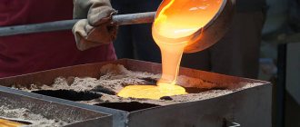
Next, heated metal is poured into the resulting mold. The contents are cooled and sent for beating, which is done using hammers. Castings obtained by this method are highly accurate.
The technology has virtually no disadvantages, and its advantage is the ability to produce elements from alloys that cannot be machined, as well as the production of connected castings with precise dimensions, which are necessary to obtain equipment components and do not require their additional assembly from small parts. Model casting is used in pilot, serial and mass production. In addition to high strength, these castings have good surface finish. This method is used for the production of important key parts.
Casting stages:
- the model is made of low-melting material;
- parts are assembled into blocks;
- surrounded by a ceramic shell that hardens and forms a shape;
- with further heating of the mold, the casting model melts and is removed;
- Metal is poured into the cavities that appear (gating system), which exactly repeats the original shape of all elements of the future part.
Manufacturing of lost wax models
For this purpose, low-melting compounds are used, which consist of paraffin, ceresin, wax and other components. These compositions must have the following properties:
- melting temperature 60–81.6 °C;
- stable linear shrinkage and expansion should be kept to a minimum;
- good fluidity of the material;
- good strength and hardness in the frozen state;
- does not stick to the surface, minimal ash formation;
- do not enter into chemical reactions with refractory materials of the mold; absence of harmful fumes during heating;
- repeated use;
- low cost of component materials.
The essence is that the model material must fill all the elements of the form and prevent it from being damaged. And subsequently, without causing damage, it will flow out of the mold, freeing up space for metal filling.
Scope of technology
The scope of application of this method is the production of castings weighing from several grams to tens of kilograms. These are cases and elements of devices, cutting and medical instruments, parts for cars, photo and video equipment, sewing and textile equipment, for performing some elements of artistic casting, as well as in the jewelry industry.
Lost wax models are made in molds from paraffin, wax, and stearic compounds, including fatty acids. These compositions are characterized by high elasticity, completely fill all cavities and give a clear imprint.
The use of casting technology opens up enormous potential for engineers, making it possible to design complex thin-walled structures and connect individual parts into compact, solid-cast units. At the same time, the weight and dimensions of products are significantly reduced, non-standard elements necessary in the process of accelerated development of technical progress are created, designs become more complex, many components and assemblies are modified, improved and adjusted. Over time, the composition of the castings was also modified. In some cases, it was necessary to create heat-resistant alloys, which were obtained by using nickel.
Machines for filling molds with model composition
At the next stage, the main equipment is machines for filling molds with model composition. The main method is to press the paste into the working cavity of the mold, which ensures the accuracy of the model and the low roughness of its surfaces. The paste is prepared using installations similar to those shown in Fig. 4 . In large quantities, models with feeders for castings are manufactured on a ten-position rotary machine 61201 (Fig. 5) with a capacity of 400 press-ins per hour or on a single-station machine 61101 with a capacity of 63 press-ins per hour.
Rice. 5. Ten-position carousel automatic machine model 61201A for the production of model links in mechanized molds
After the model composition has hardened, the mold is automatically opened, the model is pushed into a bath of cold water, from where it is sent along a water conveyor to the model assembly area. The models are stored either in cold running water or in thermostats. Simultaneously with the production of the casting model, models of the elements of the gating system are made: the riser and funnel.
In single, small-scale and mass production, models are made in non-automated molds using a 6A54 installation - the molds are filled with a syringe machine (Fig. 6) or a manual syringe, and then placed on a ten-position rotary table.
Syringe machines for making wax models come in a C-shaped design and with four guides.
Rice. 6. Four-guide injection machine
They are produced with press clamping forces from 150 to 1000 kN with a working space for the mold with a side of 360 to 1020 mm.
The process of pressing the model mass is controlled by a control system based on a programmable logic controller (PLC) and can be performed in three options, depending on the degree of complexity of the control system and the characteristics of production and the assigned tasks:
- A standard control system, where the PLC controls only the injection mode of the model mass and its temperature through the sequential operation of various systems of the syringe machine. With this control system, injection of the model mass occurs at only one speed. Changeover to each new mold is performed manually.
- Simplified electronic control system. In this version, the control system is equipped with a black and white touch screen operator interface for controlling the machine and provides single-stage control of pressure, speed and flow acceleration during pressing. Changeover when changing a part occurs automatically by calling the appropriate program.
- Fully electronic control system. The most complete version of the injection machine control system is designed for the production of complex models with different section thicknesses and/or ceramic cores (for example, models of turbine blades). In this version, the control system is equipped with a color touch screen operator interface and provides multi-stage control of pressure, speed and acceleration of the mass flow to prevent breakage of fragile ceramic rods during pressing of the mass. The system provides graphical display of model mass pressure and flow rate, storage of up to 4000 programs, system self-diagnosis and fault messages to facilitate maintenance.
Casting alloy selection
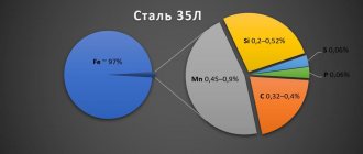
The modern process of making castings from models involves a serious approach to the choice of casting alloy. They are made from various casting alloys: carbon and alloyed, corrosion-resistant, heat-resistant and heat-resistant steels, non-ferrous alloys and cast iron-based compositions.
When producing foundry products, the conditions in which they will function are taken into account. The material of the castings depends on this. Thus, for the production of highly hermetic housings, a metal is selected that is not prone to the formation of shrinkage looseness and porosity. For components requiring high heat resistance - nickel compounds.
When choosing a casting alloy, it is necessary to have a complete understanding and exact requirements for the casting material. Clearly group the working conditions and purpose of future parts. This will make it possible to most correctly select the required alloy, taking into account its specific characteristics.
The advantage of casting according to models
The positive qualities of the technological process include high precision casting of the part up to class 4 accuracy with a clean surface that does not require additional processing. An important feature of the method is also the ability to obtain a product of complex configuration, the usual manufacturing method of which would require assembly from individual elements. Manufacturing castings from hard metal alloys makes it possible to obtain products with surface roughness up to class 6 from Rz=20 microns to Ra=1.25 microns in accordance with the requirements of GOST 2789–59.
Casting equipment
When performing work related to lost wax casting, knowledge and special equipment are needed. These are original and compact systems necessary for high-quality filling of the mold at optimal speed and obtaining metal of the required density. Their work will eliminate the formation of voids and non-metallic inclusions, which will significantly improve the quality and performance characteristics of future products.
Each cast part is an original design that requires an independent gating-feeding system (GFS) for a separate casting. At the same time, they have a lot in common - the dimensions of the walls, nodes, connections. This makes it possible to use typical LPS designs and develop standard calculation methods.
During the production process, automatic machines are used to prepare the model composition and manufacture elements. These are units for preparing mixtures, lines for cooling molds, installations for preparing coatings, boiler claves for removing compositions, equipment for firing ceramic molds, hydraulic hammers, etc.
Machines for preparing model composition
At the beginning of the technological chain, a model composition is prepared. For this, an automatic machine 61701 is used, consisting of devices for supplying solid and liquid components of the mixture, dispensers, containers and mixers. Low-melting model compositions are prepared by melting the components in water or oil baths with electrical heating.
Air in an amount of 8 is mixed into the model composition. . .12% of volume For this purpose, gear, piston and paddle mixers are used.
Rice. 4. Diagram of a gear mixer for preparing a paste-like model composition with air: 1 - shafts; 2 — wheels; 3 - partitions; 4 — outlet; 5 – mixer drive
Continuous gear mixers (Fig. 4) have two shafts 1 on which gears 2 are mounted. Each pair of wheels is separated from the adjacent one by a partition 3. In each pair, one of the wheels is loosely mounted on the shaft, and the second is secured to the shaft with a key; in the adjacent pair, it is the other way around. The shafts rotate from a common drive 5 in one direction. Therefore, on one shaft, even and on the other, odd gears rotate along with the shaft, setting the freely mounted paired wheels in motion. Adjacent pairs of wheels rotate in different directions. The width of each pair decreases in the direction of movement of the model composition to create pressure and move the paste. The liquid model composition is fed into the neck of the mixer along with air and, after mixing by the first pair of wheels, is squeezed out through hole 4 in partition 3 into the adjacent section, where it is mixed in the opposite direction and moves upward to hole 4 in the next partition. During the mixing process, the model composition is intensively cooled, turning into a paste-like state.
Organization of foundry production
Not everyone has the opportunity to have a whole arsenal of devices for doing their own casting. Therefore, you should not carry out complex foundry work with your own hands, at home, without the use of special equipment. Entrust them to professionals who have all the necessary skills, equipment and expert knowledge.
If you have planned to open your own foundry, but feel a lack of knowledge, it is better to entrust its organization to a progressive engineering company specializing in various technologies of the foundry industry. These are specialists with extensive experience in this field, providing all types of engineering services - from the design stages, commissioning of foundry production and until it reaches high design capacity.
Defect correction methods
Minor defects are corrected by sealing with putties or mastics, impregnation with various compounds, gas or electric welding.
Sealing with putties or mastics is a decorative correction of small surface cavities. Before filling with mastic, defective areas are cleaned of dirt and degreased. After filling, the corrected area is smoothed, dried and rubbed with pumice or graphite.
Impregnation is used to eliminate porosity. The castings are immersed in an aqueous solution of ammonium chloride for 8-12 hours. Penetrating into the spaces between the metal crystals, the solution forms oxides that fill the pores of the castings.
Gas and electric welding are used to correct defects on untreated surfaces (sinks, cracks). Defects in cast iron castings are welded using cast iron electrodes and filler rods, in steel castings - with electrodes of the appropriate composition
Basic recommendations for choosing a casting method
When comparing different casting methods, the following factors must be considered.
Technological properties of the alloy.
It is not advisable to use casting in metal molds:
- with reduced fluidity of the metal, because high cooling rates lead to rapid cooling and crystallization of the molten metal, which can cause the formation of underfills and joints;
- with a high tendency of the material to shrink, since cracks may form due to the low compliance of the mold, which prevents the free shrinkage of the casting in the mold.
Complexity of the casting shape.
Depending on the configuration, size, weight and required number of rods, castings are divided into six complexity groups. The simplest castings belong to the first group, which is characterized by smooth and straight outer surfaces with the presence of low reinforcing ribs, flanges, holes, as well as simple internal surfaces. Typical products are covers, flanges, couplings, trolley wheels. The most complex castings belong to the sixth group, which is characterized by curved outer surfaces having ribs, brackets and flanges of considerable length, intersecting each other at different angles, as well as internal cavities of a particularly complex configuration with difficult exits to the surface of the casting. Typical products are the beds of special metal-cutting machines, complex pump casings, and hydraulic turbine impellers.
Castings with complex configurations are produced by injection molding, investment casting, or sand molds. Chill casting produces castings with a simple external configuration, and centrifugal casting produces castings of the type of rotating bodies. The thinnest-walled castings are produced by investment casting and injection molding.
3. Quantity.
In conditions of large-scale or mass production, casting methods using metal or shell molds are cost-effective. But if it is necessary to produce one or just a few castings (single production), then it is irrational to make an expensive mold for this or use expensive lost-wax casting. Therefore, in this case, the use of sand casting, for which inexpensive wooden models can be used, can pay off and is the most rational.
4. Required geometric accuracy and surface quality.
You should choose a method that ensures the specified dimensional accuracy and surface roughness. The high quality of the surface makes it possible to either eliminate subsequent machining or perform it with minimal allowances. This makes it possible to preserve the casting skin during machining, which has increased hardness and wear resistance, and to reduce the cost of finished parts by saving metal. However, this increases the costs of foundry equipment and accessories, their repair and maintenance. Therefore, when choosing a method for producing a casting, a technical and economic analysis should be carried out not only of one blank (foundry), but of two stages of production - blank (foundry) and machining.
The most accurate indicator that determines the effectiveness of using a particular method is the cost of the product.
When choosing the optimal method for producing castings, as a rule, it is necessary to conduct a comparative analysis of possible casting options and their technological indicators, approximately presented in table. 1L.
Formulation of the problem
One of the main problems faced by specialists at the Voronezh Mechanical Plant was the issue of providing power to the casting with metal, since the complexity of manufacturing the ceramic shell and the duration of the technological process made it difficult to find optimal crystallization conditions.
To solve this problem, the LVMFlow automated casting process modeling system was used to analyze the crystallization processes of the “Body” type casting, which has a number of advantages compared to similar systems on the world market. LVMFlow is based on the finite difference method (FDM), which allows one to analyze the filling of a mold with a melt, taking into account preheating of the mold. In this case, there is no need to draw the ceramic shell in an external design program, since the system allows you to create a shell shape within a few seconds.
| Rice. 1a. Vertical location of the casting | Rice. 1b. Horizontal location of the casting |
The design of the part can be presented in the form of two cylindrical bodies interpenetrating at an angle of 90° with extended thin walls and massive flanges. Its peculiarity is the pronounced variation in thickness (the ratio of wall and flange thicknesses is 30:100 mm) and the presence of thermal centers at the transition points from thin to thick elements.
Based on the known patterns of the formation of castings, it can be argued that casting such a design will lead to the appearance of defects of a shrinkage nature. To avoid this and ensure tightness, it is necessary to achieve consistent development of crystallization of the casting in compliance with the principle of directional solidification. Of course, achieving the desired result largely depends on the location of the casting during pouring, so two main options for such an arrangement were considered: vertical (Fig. 1a) and horizontal (Fig. 1b).
In the first case, the ceramic shell was placed in such a way that the casting passage channel was formed in a horizontal position, and the gate channel body was formed in a vertical position. Individual profits were installed for each massive element in the casting (three flanges). During pouring, the longest walls were oriented vertically in the ceramic shell. With this arrangement, the walls are fed during the solidification process sequentially through massive flanges towards the profits.
On the central and two side flanges, local profits were installed (one annular and two rectangular), communicating with each other through gating passages, which made it possible to supply hot metal to the side profits at the final stage of pouring. The melt entered the shell cavity through a metal receiver and four distribution channels.
The design of the LPS is shown in Fig. 2.
Rice. 2. Scheme of the gating-feeding system 1 - melt; 2 - ceramic funnel; 3 - thrust; 4 — metal receiver; 5 - distribution channel; 6 - profit of rectangular section; 7 - sprue channel; 8 - ring profit; 9 - casting; 10 - refrigerator
In the area of the massive “blind pocket” located in the lower part of the casting, a refrigerator was used to enhance the direction of solidification of the metal. The ceramic shell was molded into a flask with fireclay filler, and the melt was poured into molds heated to 750 °C. The melt temperature was about 1590 °C.
The quality of the resulting castings was controlled using radiographic examination; and the tightness of the housings - through hydrostatic tests.
Analysis of the data obtained showed that the characteristic defect of body castings under such conditions of casting formation is looseness and porosity. This is most evident in the walls of a horizontal passage channel. At the same time, the most severely affected areas were the transition points from the thin-walled channel elements to the flanges and the massive part of the blind channel. Somewhat less looseness is inherent in the vertically located walls of the lower tier of the body and the vertically oriented side flanges.
Since the resulting distribution of defects did not meet the requirements for the tightness of the castings, the second method was used - horizontal arrangement.
Forming a casting in a ceramic shell is a very complex process, so it is almost impossible to take into account all the factors influencing the crystallization process. It is not possible to experimentally test all variants of LPS due to the complexity and duration of the process of obtaining a casting. It takes several weeks to develop a variant of the gating-feeding system before obtaining a pilot casting; therefore, the LVMFlow automated modeling system for casting processes was used to analyze the solidification process of the “Case” casting.
Rice. 3. Initial geometric model
The horizontal arrangement of the casting provided for the presence of five profits, one of which was installed in the center of the casting, three on the flanges, and another one on the conical part of the casting (in the area of the saddle). As with the vertical location of the casting, all the profits were interconnected into a single whole, which at the final stage of casting made it possible to ensure the supply of hot metal to the profits.
Based on the initial drawings of the casting, Consistent Software Voronezh specialists, together with employees of the department of the chief metallurgist of the Voronezh Mechanical Plant, built a three-dimensional model of the “Case” casting with LPS (Fig. 3).
When constructing the initial geometric model of the casting (GM), external design programs Autodesk Inventor Series and Unigraphics were used.
Materials used
Materials for the manufacture of the shell are divided into the following groups: base materials, binders, solvents and additives. The first include dust, used for preparing suspensions, and sand, intended for sprinkling it. They are quartz, chamotte, zircon, magnesite, high-alumina chamotte, electrocorundum, chromium magnesite and others. Quartz is widely used. Some shell base materials are obtained in a ready-to-use form, while others are pre-dried, calcined, ground, and sifted. A significant disadvantage of quartz is its polymorphic transformations, which occur with temperature changes and are accompanied by a sharp change in volume, ultimately leading to cracking and destruction of the shell.
Smooth heating of the molds in order to reduce the likelihood of cracking, which is carried out in the supporting filler, increases the duration of the technological process and additional energy costs. One of the options for reducing cracking during calcination is to replace pulverized quartz sand as a filler with dispersed quartz sand of a polyfractional composition. At the same time, the rheological properties of the suspension are improved, the crack resistance of the molds is increased, and defects due to blockages and breakdown of shells are reduced.
