GOST (short name for State Standard, State Standard, GOST) is one of the important categories of the system of welding standards in the USSR, which is still a standard in modern CIS countries. Adopted by a body such as the Interstate Council for Standardization, Metrology and Certification.
During the period of socialism, all state Welding standards were preserved for the production of products, and were mandatory for use in those areas of technology that were determined by the scope of possible use of GOST.
GOST standards: welding processes
GOST 19521-74 Welding of metals. Classification
GOST 3.1705-81 Unified system of technological documentation. Rules for recording operations and transitions. Welding
GOST 2601-84 Welding of metals. Terms and definitions of basic concepts
GOST 11969-79 Fusion welding. Basic provisions and their designations
GOST 29273-92 Weldability. Definition
GOST 23870-79 Weldability of steels. Method for assessing the effect of fusion welding on the base metal
GOST 30430-96 Arc welding of structural cast iron. Process requirements
GOST 30482-97 Electroslag welding of steels. Process requirements
GOST 29297-92 Welding, high-temperature and low-temperature soldering, soldering of metals. List and symbols of processes
GOST 2.312-72 Unified system of design documentation. Conventional images and designations of seams of welded joints.
GOST 20549-75 Vacuum diffusion welding of working elements of separation and forming dies. Typical technological process
GOST R ISO 17659-2009 Welding. Multilingual terms for welded joints.
GOST R ISO 857-1-2009 Welding and related processes. Dictionary. Part 1. Metal welding processes. Terms and Definitions.
Appendix YES (reference)
Information on the compliance of reference international standards with reference national standards of the Russian Federation (and interstate standards acting as such)
Table DA.1
| Designation of the reference international standard | Degree of compliance | Designation and name of the corresponding national standard |
| ISO 80000-1:2009 | — | * |
| *There is no corresponding national standard. Before its approval, it is recommended to use the Russian translation of this international standard. A translation of this international standard is available from the National Agency for Control and Welding (NAKS). | ||
GOST: submerged arc welding
GOST 8713-79 Submerged arc welding. Welded connections. Main types, structural elements and dimensions
GOST 11533-75 Automatic and semi-automatic submerged arc welding. Welded connections at acute and obtuse angles. Main types, structural elements and dimensions
GOST welding + in shielding gases
GOST 14771-76 Arc welding in shielding gas. Welded connections. Main types, structural elements and dimensions
GOST 23518-79 Arc welding in shielding gases. Welded connections at acute and obtuse angles. Main types, structural elements and dimensions
Basic designations
Welded structures use materials of different thicknesses, sizes and shapes; in addition, the parts may have different locations in relation to each other. The designation of a weld seam in the drawing directly depends on the relative position of the welded structural elements. Only 5 types of connections have been installed (according to GOST 5264 and GOST 14771):
- “C” docking;
- “C” end;
- "U" is angular;
- "N" overlap;
- "T" Tee.
A butt in the drawing is a connection of elements that are located on the same surface or plane. The process of welding parts occurs on adjacent end sides.
End connection “C” is the welding of elements along the end faces of parts whose side surfaces are together. This method is used when welding parts made of thin metal in order to eliminate the possibility of burn-through. The designation of welds in the drawings with the same letters, for example, butt and end, must have an explanation regarding the specific type of weld used.
Designation of welding seams in drawings with a capital letter H when welding using the overlap method. When welding, parts are arranged on parallel lines in such a way that one element partially overlaps the other.
T is the designation on drawings for a T-weld. The end part of one part is connected to the end part of another part at a certain angle (maybe 90 degrees).
The last type “U” - angular, is a seam that is obtained as a result of the arrangement of the welded elements at a right, acute or obtuse angle relative to each other. A weld seam in a drawing, regardless of what type of welding was used, can be designated as visible or invisible.
The visible type of seam is indicated by a solid line, the invisible seam is indicated by a dotted line. A single weld point, which is visible, is indicated in the drawings with a “+” sign; an invisible one does not have any designations.
If the drawing has seams that were made according to the same standards, then the welding drawings and designations will be the same, but this should be indicated in the technical requirements of this drawing.
In the drawings, identical seams can be numbered, but only if all seams are identical to each other and have a one-sided image, for example, only on the front or back side. If the seam does not have any designation, it should be marked on the drawing as a line - a leader that does not have flanges.
The designation of a weld seam in the drawing of a symmetrical product should be represented by leader lines, and the seams themselves should be depicted only on one of the symmetrical parts of the product. But this is only possible if there is an axis of symmetry.
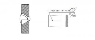
Example No. 1
In the picture above you see a butt seam in which one edge has a curved bevel. The connection itself is double-sided, made by manual arc welding. There is no gain on either side. On the front side the seam roughness is Rz 20 µm, and on the back side it is Rz 80 µm.
Example No. 2
Here you can see that the seam is corner and double-sided, it has no bevels or edges. This connection is made by automatic welding and using flux.
Example No. 3
Here we have a butt seam again, but without bevels or edges. The connection is one-sided, with a lining. The seam is made using heated gas and welding wire.
GOST: aluminum welding
GOST 14806-80 Arc welding of aluminum and aluminum alloys in inert gases. Welded connections. Main types, structural elements and dimensions
GOST 27580-88 Arc welding of aluminum and aluminum alloys in inert gases. Welded connections at acute and obtuse angles. Main types, structural elements and dimensions
GOST spot welding
GOST 14776-79 Arc welding. Spot welded connections. Main types, structural elements and dimensions
GOST 28915-91 Pulse laser welding. Spot welded connections. Main types, structural elements and dimensions
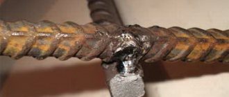
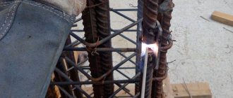
What is a welded joint
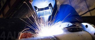
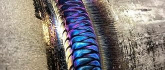
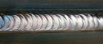
The welding process is a technological operation of forming a monolithic joint. The area where the material of the joined parts melted and solidified is called a weld.
Kinds
The welded joint is divided into:
- Stykova. The connection is formed along the end surfaces of the parts. It is carried out with or without edge processing. Marking "C".
- Overlapping. The planes of the parts are parallel to each other and partially overlap one another. Marking "N".
- Tavrovy. The end of the part is adjacent to the plane of another part at an angle. The seam is located along the joint. Marking "T".
- Angular. The main planes of the joined parts in the welding zone are located at an angle to each other. Marking "U".
- Tortsovy. The semi-finished product is pressed against the side surfaces. The seam is formed by fusing metal onto the ends of the products.
The seam is performed:
- Unilateral. Deposition is carried out on one side of the connection (joint).
- Bilateral. Processing occurs on both sides.
GOST: pipeline welding
GOST 16037-80 Welded connections for steel pipelines. Main types, structural elements and dimensions
GOST 16038-80 Arc welding. Welded connections for pipelines made of copper and copper-nickel alloy. Main types, structural elements and dimensions
GOST 16310-80 Welded joints made of polyethylene, polypropylene and vinyl plastic. Main types, structural elements and dimensions
GOST 15164-78 Electroslag welding. Welded connections. Main types, structural elements and dimensions
GOST 15878-79 Contact welding. Welded connections. Structural elements and dimensions
GOST 16098-80 Welded joints made of two-layer corrosion-resistant steel. Main types, structural elements and dimensions
GOST 16310-80 Welded joints made of polyethylene, polypropylene and vinyl plastic . Main types, structural elements and dimensions.
GOST 16130-90 Wire and rods made of copper and copper-based alloys for welding. Specifications
The need to use symbols
Scheme for designating welds on drawings in accordance with GOST
Properly compiled design documentation will ensure high-quality work of the entire chain of specialists - from the developer to the control department employee. Symbols for welded joints provide a complete list of characteristics: joining method, type and shape of the joint, geometric parameters, welding conditions, its sequence in the process, joint tightness, strength, etc.
Designations of welds on drawings are used not only during the manufacturing process, but also when checking the finished product. An employee of the control department checks the parameters of the finished product with the requirements of the design documentation: he can check the geometric parameters of the weld, the quality of work, etc.
GOST standards: welding materials
GOST R EN 13479-2010 Welding materials. General requirements for filler materials and fluxes for fusion welding of metals
GOST R 53689-2009 Welding materials. Technical conditions for the supply of filler materials. Product type, dimensions, tolerances and markings
GOST 7871-75 Welding wire made of aluminum and aluminum alloys. Specifications
GOST 9466-75 Coated metal electrodes for manual arc welding of steels and surfacing. Classification and general technical conditions
GOST R ISO 2560-2009 Welding materials. Coated electrodes for manual arc welding of unalloyed and fine-grained steels . Classification
GOST R ISO 3580-2009 Welding materials. Coated electrodes for manual arc welding of heat-resistant steels . Classification
GOST R ISO 3581-2009 Welding materials. Coated electrodes for manual arc welding of corrosion-resistant and heat-resistant steels . Classification
GOST 2246-70 Steel welding wire. Specifications
GOST 9467-75 Coated metal electrodes for manual arc welding of structural and heat-resistant steels. Types
GOST 10051-75 Coated metal electrodes for manual arc surfacing of surface layers with special properties. Types
GOST 10052-75 Coated metal electrodes for manual arc welding of high-alloy steels with special properties. Types
GOST 10543-98 Steel surfacing wire. Specifications
GOST 21448-75 Alloy powders for surfacing. Specifications
GOST 21449-75 Rods for surfacing. Specifications
GOST 23949-80 Non-consumable tungsten welding electrodes. Specifications
GOST 26101-84 Flux-cored surfacing wire. Specifications
GOST 26271-84 Flux-cored wire for arc welding of carbon and low-alloy steels. General technical conditions
GOST 26467-85 Powder surfacing tape. General technical conditions
GOST 9087-81 Fused welding fluxes. Specifications
GOST 28555-90 Ceramic fluxes for arc welding of carbon and low-alloy steels. General technical conditions
GOST R ISO 14174-2010 Welding materials. Fluxes d
GOST 30756-2001 Fluxes for electroslag technologies
GOST 5.1215-72 Metal electrodes grade ANO-4 for arc welding of low-carbon structural steels. Requirements for the quality of certified products
GOST 22366-93 Iron-based sintered electrode surfacing tape. Technical conditions.
We'll call you back in 30 seconds.
GOST R ISO 2553-2017 GOST R ISO 6947-2017 GOST R ISO 13920-2017 GOST R 55554-2013 GOST R ISO 6520-1-2012 GOST R ISO 14174-2010 GOST R ISO 14175-2010 GOST R EN 13479-201 0 GOST R EN 12074-2010 GOST R ISO 2560-2009 GOST R 53689-2009 GOST R ISO 3581-2009 GOST R ISO 3580-2009 GOST 10543-98 GOST 19249-73 GOST 21449-75 GOST 5264-80 GOST 9467- 75 GOST 21448 -75 GOST 23178-78 GOST 15164-78 GOST 14806-80 GOST 16038-80 GOST 9087-81 GOST 25445-82 GOST 26271-84 GOST 26101-84 GOST 27580-88 GOST 28915-91 GOST 2246-70 GOST 5.917-71 GOST 5.1215-72 GOST 10051-75 GOST 11533-75 GOST 10052-75 GOST 11534-75 GOST 7871-75 GOST 23518-79 GOST 14776-79 GOST 15878-79 GOST 16037-80 GOST 23949-80 GOST 26467-85 GOST 16130 -90 GOST 30430-96 GOST 30242-97 GOST 30482-97 GOST R 52222-2004 GOST 28555-90 GOST 30756-2001 GOST 14771-76 GOST 9466-75 GOST 8713-79
- gost-5264-80.pdf (873.86 KiB)
GOST 5264-80
GOST 5264–80 Group B05
INTERSTATE STANDARD
MANUAL ARC WELDING. WELDED CONNECTIONS Basic types, structural elements and dimensions Manual arc welding. Welding joints. Main types, design elements and dimensions
MKS 25.160.40 OKP 06 0200 0000
Date of introduction 1981−07−01
By Decree of the USSR State Committee for Standards dated July 24, 1980 N 3827, the introduction date was set from July 1, 1981
The validity period was lifted according to Protocol N 5−94 of the Interstate Council for Standardization, Metrology and Certification (IUS N 11−12−94)
INSTEAD GOST 5264–69
EDITION (November 2009) with Change No. 1, approved in January 1989 (IUS 4−89), Amendment (IUS 9−2009).
1. This standard establishes the main types, structural elements and dimensions of welded joints made of steels, as well as alloys on iron-nickel and nickel bases, performed by manual arc welding. The standard does not apply to welded joints of steel pipelines in accordance with GOST 16037–80.
2. The main types of welded joints must correspond to those indicated in Table 1.
3. Structural elements and their dimensions must correspond to those indicated in Table 2−54.
Table 1
| Connection type | Shape of prepared edges | Character of the weld | Cross-sectional shape | Thickness of welded parts, mm | Connection symbol | |
| prepared edges | weld | |||||
| Butt | With beaded edges | Unilateral | 1−4 | C1 | ||
| 1−12 | S28 | |||||
| With flange on one edge | 1−4 | NW | ||||
| No beveled edges | C2 | |||||
| Single-sided with removable lining | 1−4 | C4 | ||||
| Single sided with remaining lining | C5 | |||||
| Single-sided locking | 1−4 | C6 | ||||
| Bilateral | 2−5 | C7 | ||||
| No bevel of edges followed by gouging | 6−12 | S42 | ||||
| With one edge beveled | Unilateral | 3−60 | C8 | |||
| Single-sided with removable lining | C9 | |||||
| Single sided with remaining lining | C10 | |||||
| Single-sided locking | C11 | |||||
| Bilateral | C12 | |||||
| With a curved bevel of one edge | 15−100 | C13 | ||||
| With a broken bevel on one edge | C14 | |||||
| With two symmetrical bevels on one edge | 8−100 | C15 | ||||
| With two symmetrical curved bevels on one edge | 30−120 | C16 | ||||
| With two asymmetrical bevels on one edge | 12−100 | C43 | ||||
| With beveled edges | Unilateral | 3−60 | C17 | |||
| Single-sided with removable lining | C18 | |||||
| Single sided with remaining lining | 6−100 | C19 | ||||
| Single-sided locking | 3−60 | S20 | ||||
| Bilateral | S21 | |||||
| With beveled edges followed by gouging | 8−40 | S45 | ||||
| With curved edges | 15−100 | S23 | ||||
| With broken bevel edges | S24 | |||||
| With two symmetrical edge bevels | 8−120 | S25 | ||||
| With two symmetrical curved edge bevels | 30−175 | S26 | ||||
| With two symmetrical broken edges | 30−175 | S27 | ||||
| With two asymmetrical edge bevels | 12−120 | C39 | ||||
| C40 | ||||||
| Angular | With flange on one edge | Unilateral | 1−4 | U1 | ||
| 1−12 | U2 | |||||
| No beveled edges | 1−6 | U4 | ||||
| 1−30 | ||||||
| Bilateral | 2−8 | U5 | ||||
| 2−30 | ||||||
| With one edge beveled | Unilateral | 3−60 | U6 | |||
| Bilateral | U7 | |||||
| With two symmetrical bevels on one edge | 8−100 | U8 | ||||
| With beveled edges | Unilateral | 3−60 | U9 | |||
| Bilateral | U10 | |||||
| Tavrovoe | No beveled edges | Unilateral | 2−40 | T1 | ||
| Bilateral | T3 | |||||
| With one edge beveled | Unilateral | 3−60 | T6 | |||
| Bilateral | T7 | |||||
| With a curved bevel of one edge | 15−100 | T2 | ||||
| With two symmetrical bevels on one edge | 8−100 | T8 | ||||
| 12−100 | T9 | |||||
| With two symmetrical curved bevels on one edge | 30−120 | T5 | ||||
| Overlapping | No beveled edges | Unilateral | 2−60 | H1 | ||
| Bilateral | H2 | |||||
table 2
Dimensions, mm
| Symbol of welded joint | Structural elements | , no more | ||||
| prepared edges of welded parts | weld | Nom. | Prev. off | |||
| C1 | From 1 to 2 | 0 | +0,5 | From to | From to | 2+3 |
| St. 2 to 4 | +1,0 | |||||
______________ * Size for reference.
Table 3
Dimensions, mm
| Symbol of welded joint | Structural elements | , no more | |||
| prepared edges of welded parts | weld | Nom. | Prev. off | ||
| S28 | From 1 to 2 | From to | 0 | +1 | |
| St. 2 to 6 | |||||
| St. 6 to 9 | +2 | ||||
| St. 9 to 12 | +3 | ||||
Table 4
Dimensions, mm
| Symbol of welded joint | Structural elements | , no more | ||||
| prepared edges of welded parts | weld | Nom. | Prev. off | |||
| C3 | From 1 to 2 | 0 | +0,5 | From to | From to | 2+3 |
| St. 2 to 4 | +1,0 | |||||
_____________ * Size for reference.
Table 5
Dimensions, mm
| Symbol of welded joint | Structural elements | , Not more | |||||
| prepared edges of welded parts | weld | Nom. | Prev. off | Nom. | Prev. off | ||
| C2 | From 1.0 to 1.5 | 0 | +0,5 | 6 | 1,0 | ±0,5 | |
| St. 1.5 to 3.0 | 1 | ±1,0 | 7 | 1,5 | ±1,0 | ||
| St. 3.0 to 4.0 | 2 | +1,0 -0,5 | 8 | 2,0 | |||
Table 6
Dimensions, mm
| Symbol of welded joint | Structural elements | , no more | , no more | |||||
| prepared edges of welded parts | weld | Nom. | Prev. off | Nom. | Prev. off | |||
| C4 | From 1.0 to 1.5 | 0 | +0,5 | 6 | 4 | 1,0 | ±0,5 | |
| St. 1.5 to 3.0 | 1 | ±1,0 | 7 | 6 | 1,5 | ±1,0 | ||
| St. 3.0 to 4.0 | 2 | +1,0 -0,5 | 8 | 2,0 | ||||
Table 7
Dimensions, mm
| Symbol of welded joint | Structural elements | , no more | |||||
| prepared edges of welded parts | weld | Nom. | Prev. off | Nom. | Prev. off | ||
| C5 | From 1.0 to 1.5 | 0 | +0,5 | 6 | 1,0 | ±0,5 | |
| St. 1.5 to 3.0 | 1 | ±1,0 | 7 | 1,5 | ±1,0 | ||
| St. 3.0 to 4.0 | 2 | +1,0 -0,5 | 8 | 2,0 | |||
Table 8
Dimensions, mm
| Symbol of welded joint | Structural elements | , no more | |||||
| prepared edges of welded parts | weld | Nom. | Prev. off | Nom. | Prev. off | ||
| C6 | From 1.0 to 1.5 | 0 | +0,5 | 6 | 1,0 | ±0,5 | |
| St. 1.5 to 3.0 | 1 | ±1,0 | 7 | 1,5 | ±1,0 | ||
| St. 3.0 to 4.0 | 2 | +1,0 -0,5 | 8 | 2,0 | |||
Table 9
Dimensions, mm
| Symbol of welded joint | Structural elements | , no more | ± 1 | |||
| prepared edges of welded parts | weld | Nom. | Prev. off | |||
| C7 | 2 | 2 | ±1,0 | 8 | 1,5 | |
| St. 2 to 4 | 9 | |||||
| St. 4 to 5 | +1,5 -1,0 | 10 | 2,0 | |||
Table 10
Dimensions, mm
| Symbol of welded joint | Structural elements | ±1 | ±1 | , no more | , no more | |
| prepared edges of welded parts | weld | |||||
| S42 | From 6 to 8 | 4 | 7 | 10 | 12 | |
| St. 8 to 10 | 6 | 9 | 12 | 14 | ||
| St. 10 to 12 | 8 | 11 | 14 | 16 | ||
Table 11
Dimensions, mm
| Symbol of welded joint | Structural elements | |||||
| prepared edges of welded parts | weld | Nom. | Prev. off | Nom. | Prev. off | |
| C8 | From 3 to 5 | 8 | ±2 | 0,5 | +1,5 -0,5 | |
| St. 5 to 8 | 12 | |||||
| St. 8 to 11 | 16 | |||||
| St. 11 to 14 | 20 | |||||
| St. 14 to 17 | 24 | ±3 | +2,0 -0,5 | |||
| St. 17 to 20 | 28 | |||||
| St. 20 to 24 | 32 | |||||
| St. 24 to 28 | 35 | |||||
| St. 28 to 32 | 38 | |||||
| St. 32 to 36 | 41 | |||||
| St. 36 to 40 | 44 | |||||
| St. 40 to 44 | 49 | ±4 | ||||
| St. 44 to 48 | 53 | |||||
| St. 48 to 52 | 56 | |||||
| St. 52 to 56 | 60 | |||||
| St. 56 to 60 | 64 | |||||
Types of welded joints
The type is determined by the relative position of the parts being connected. According to GOST 5264-80 and GOST 14771-76, there are five types of welded joints:
| No. | Name | Description | Marking |
| 1 | Butt | The elements to be joined are placed in the same plane, welded at adjacent ends, and edge processing is possible. Requires precise adjustment of joined parts and is highly durable. | WITH |
| 2 | Lap | Parallel planes of parts overlap each other. They are inferior to butt joints in terms of reliability under load, and are not so demanding in terms of accuracy of fit. | N |
| 3 | Tavrovy | The end of the part is welded to the surface of another part of the structure vertically or at an angle. Not recommended for bending loads. | T |
| 4 | Angular | The surfaces of the joints to be connected are inclined relative to each other (the angle of contact of the edges is more than 300), welding is carried out at the ends of the products. | U |
| 5 | Tortsevoy | The ends of the nodes whose side surfaces are in contact are connected. To do this, a layer of metal is fused to the ends. Used when connecting thin elements to avoid burning. | WITH |
According to GOST, welded joints can be single-sided (SS) or double-sided (BS), depending on the metal deposit on one or both sides. There are also single-layer and multi-layer welding.
The choice of welding seam is determined by the design requirements for the connection.
Types of welded joints
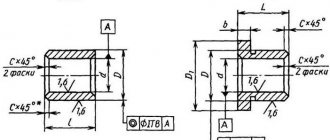
Creating an Assembly
To create an assembly, you need to make 3D models of all the parts included in it.
You can create the details yourself or download them from the link at the end of the article.
It is advisable to save all documents related to the assembly in one folder.
For each part, add a specification object: Specification→Add object→Details→Create.
Create an assembly: XYZ orientation, insert the Plate first, then the Cylinder and Eye. More details and overlapping mates.
Then we create specification objects for the assembly: Specification → Create specification objects.
Now a new document has appeared in the folder with assembly documents - a specification containing information about the components of the assembly.
Assembly drawing of a welded joint
Let's create an associative assembly drawing of the product Support.
Turn off the left view of the product and insert two views into the field of the A4 drawing.
As you can see, the views are too bulky, so let's set the scale for them to 1:2. Select them, in the context menu (RMB) select the Scale command, select 1:2.
The front view should be replaced by a frontal section, so we delete it.
Create a cut.
This cut needs to be adjusted because the eyelet should not be shaded.
Call the Drawing Tree window: View→Drawing Tree. We get to the Eyelet component and in the Context menu select the Don’t cut command. Rebuilding the assembly
It is also necessary to remove the letter designation of the cut and the trace of the cutting plane. To do this, we create invisible layers to which we transfer these designations.
Working with specifications
Now we arrange the positions of the parts in the drawing arbitrarily; we will edit them later.
To edit positions in a welded joint drawing, you need to link it to a specification file. Open the specification, open the Assembly Management window → click “+” Connect document and add a link to the assembly drawing.
Drawings: GOST requirements
Welding, a designation on a GOST drawing, where there are identical components of one part that were welded with seams of the same type, can be designated as leader lines. The seams can be indicated only for one part of the part; the best option is an image next to which there is a line - a leader.
Some welds may not be marked with leader lines in the drawing, but are indicated as welding explanations in the technical requirements and notes to the drawing. The designation of the weld seam in the drawing is a mandatory condition, it is in the technical requirements, it must contain information about the type, dimensions of the parts and their design features, the location of the weld seams in the cross section.
All seams or a group of seams in the drawing are given the same set of requirements, which should be located either in the table or in the technical description.
Welding (designation on the GOST drawing) must fully comply with all established requirements. A well-drawn drawing is the key to fast and efficient work by welders. A drawing that is not made in accordance with GOST requirements will not be accepted by the authorities.
Sources
- https://intehstroy-spb.ru/spravochnik/oboznachenie-svarnyh-shvov.html
- https://protect.gost.ru/document.aspx?control=7&id=161216
- https://BurForum.ru/svarka/oboznachenie-svarki-na-chertezhah-po-gost.html
- https://rosstandart.msk.ru/gost/001.025.160.040/gost-14771-76/
- https://metall4all.ru/gost/gost-14771-76/
- https://ecat.simbexpert.ru/Index2/1/4294850/4294850476.htm