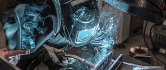
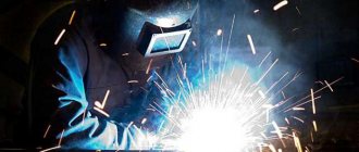
Semi-automatic welding allows for faster welding due to the continuous supply of wire, which serves as filler metal. Thus, it is possible to deposit large volumes on worn surfaces or create long seams on metal structures without the distraction of changing the electrode. The quality of the seam is much better than when working with coated consumables. But the semi-automatic device has one drawback - in addition to the device, it is also necessary to deliver a gas cylinder weighing 83 kg to the workplace. This makes the task much more difficult. A long gas hose is not always at hand. An alternative is flux cored wire welding, which eliminates the use of shielding gas. How does it work, and what are the advantages and disadvantages of the method?
Self shielding wire
To create a weld with an electric arc, it is necessary to protect the weld pool from interaction with gases in the surrounding air. For this purpose, coating of coated electrodes or inert gas is used, supplied around the filler wire from the nozzle of a semi-automatic device. But it is not always possible to deliver a heavy cylinder to the workplace, and the process with coated electrodes is too slow. Therefore, semi-automatic welding with flux-cored wire without gas was developed.
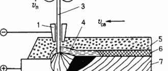
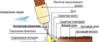
The wire structure is hollow and has several versions with one or two stiffeners. They are formed during the production of this consumable material during the process of laying the powder and turning the tubular structure. The ribs prevent the structure from creasing when lightly accidentally pressed. An electric current is supplied to the wire, which excites the welding arc. The temperature of the latter melts the metal tube from which the seam is formed and the powder contained in it. The mixture forms a gas cloud that protects the molten metal.
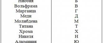
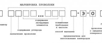
The powder inside the wire is flux. Its composition may differ, and this determines the use of the material. The presence of rutile and fluorite concentrate can reach 60%. The composition can be read on the packaging in the GOST or ISO marking, on the basis of which a decision is made on the suitability of this consumable for welding a specific type of steel.
What gas is needed
To choose which gas to use when welding semi-automatically, you need to have an idea of the physical and chemical properties of the gas. There are three main categories:
- inert;
- active;
- mixtures of gases.
Let's take a closer look at them.
The choice of gas also depends on the characteristics of the welding machine and the type of surface. For example, pure nitrogen is ideal for joining copper parts.
Acetylene
This organic compound is most widespread. The gas is lighter than air, colorless, has a specific odor, and has a high combustion temperature, which is why it is used in gas cutting of metal products.
For the industrial production of acetylene, special generators are used in which calcium carbide interacts with water.
The only drawback is difficulty in storage, since carbon carbide easily absorbs moisture from the atmosphere, which creates additional inconvenience.
Hydrogen
Widely used for joining aluminum products and plasma cutting of stainless steel. The gas is colorless and odorless. Explosive. When combined with air or water, it forms an explosive mixture. It is obtained by synthesizing water by separating oxygen and hydrogen in special generators. According to safety regulations, it is prohibited to store hydrogen in cylinders under pressure exceeding 15 MPa.
Coke
A by-product of the coke industry, which is formed during the production of coke. The gas is colorless with a pungent odor. Its storage is not subject to such stringent requirements as hydrogen, despite the fact that the gas is classified as explosive. Gas is transported using pipelines. It is not widely used due to the specifics of production. Applicable only in industrial areas.
Natural
Representatives of the organic group of hydrocarbon compounds are methane, propane and butane. Meet all requirements for welding gases. The advantages include the prevalence of this type, as well as the relatively low cost. The requirements for storage conditions are not strict - it is permissible to store cylinders outside, if a special cage with a canopy is built. Artificial synthesis is impossible. It is extracted only from natural deposits.
Pyrolysis
This type compares favorably with its counterparts - it does not need to be generated, since pyrolysis gas is released during the breakdown of petroleum products. Before use, it must be pre-cleaned due to excessive chemical activity, which can lead to corrosion of the burner. Suitable for both welding and cutting metal structures.
Clean
This group includes the following gases:
- Argon. In its pure form it is used only for argon arc welding. It is included in various mixtures as one of the components. Chemical inertness makes argon the optimal choice when working with refractory materials. It has low thermal conductivity and ionization potential.
- Helium. Another representative of the chemically inert group. Compared to argon, it has higher thermal conductivity and ionization potential.
These properties of helium provide a connection with greater heat input than argon, increasing the width of the welding profile.
- Carbon dioxide. The cheapest gas of all listed. This circumstance ensures wide popularity when carrying out work under limited budget conditions. Positive qualities include deep penetrating abilities, especially useful when joining thick sheet steel. The main disadvantage is poor arc stabilization, and as a result, a fairly large amount of splashes.
A distinctive feature of this gas is that it can be used without the addition of inert gases.
Gases used as mixture components
The most well-known additive component is oxygen. High chemical activity affects the percentage in the mixture - its mass fraction rarely exceeds 7-10%. A mixture of argon and oxygen has a specific melting pattern.
A weld made using this mixture is known as a “nail head”, named due to its external resemblance. Three-component mixtures are known, which include oxygen, argon and carbon dioxide, with different proportions, depending on the nature of the work.
Nitrogen is not widely used as a shielding gas. It is mainly used to join copper and stainless steel, since it does not react with these metals.
Gas welding mixtures and recommended areas of their application.
Varieties and applications
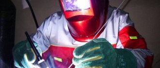
Welding with self-shielding flux-cored wire is in demand in hard-to-reach places. This can be work at heights or in underground tunnels. A small semi-automatic machine can be hung on your shoulder, and to perform welding you only need a 220V socket. Due to its compactness, this technology is widely used on construction sites and installation work. Assembly and welding of metal structures in this way is very fast. But it is not suitable for welding pipes under high pressure.
The wire is widely used due to the variety of diameters, the minimum value of which starts from 0.8 mm and ends at 2.4 mm. This allows you to weld both thin sheets of steel, with a wall thickness of 1.2 mm, and thick sides up to 7-10 mm. This method can work with carbon steel, galvanized iron and stainless steel. To do this, it is important to choose the right material for the wire itself and the type of internal filler.
Advantages and disadvantages of cored wire
The welding process using a continuous feed of self-shielding wire has several advantages:
- no need for a gas cylinder;
- easy transportation of equipment to the workplace;
- the ability to weld in hard-to-reach places (on the roof, in a tunnel);
- high speed of work compared to coated electrodes;
- low sensitivity of the arc to wind and drafts.
But this type of welding also has disadvantages. One of them is the high cost of consumables. It's not worth buying it to save on gas. Self-protecting wire pays off only in hard-to-reach places. Another disadvantage is the poor quality of the seams compared to a semi-automatic welding machine, which was used to weld in an inert gas environment. This type of welding is also not suitable for connecting pipes under pressure.
Equipment used
Automatic and semi-automatic machines are used for work; the type of mechanized welding equipment depends on the required degree of human participation in the welding process. A mechanized automatic apparatus carries out:
- arc ignition;
- mechanized supply of additive, flux or gas;
- control of current parameters;
- movement of the arc relative to the edges along a given trajectory.
The operator only monitors the operation of the machines, which consist of a tractor (self-propelled welding head) and a control unit (processor).
Mechanized tractor-type devices feed wire using pressure and feed rollers. The arc is moved in the direction of the seam manually by the welder. The main element of semi-automatic mechanization is the electric holder. Through this device, electric current is supplied to the welding zone. The arc is ignited when the circuit is closed using a start button located on the handle of the holder.
Tractor-type equipment can perform work in a fully automatic process
To supply and remove the remaining flux, bins with regulators (dispensers) are installed. Mechanized semi-automatic machines for welding in shielding gases have a special gas-electric torch, from which gas and conductive filler wire are simultaneously supplied.
Features of work
As you can see in the video, working with flux-cored wire has several specific features that a welder needs to know. To successfully conduct an arc and form a seam, it is necessary to set straight polarity. On semi-automatic machines this is done by switching contacts inside the device. The wire going to the burner is connected to the ground cable, and the wire from ground is switched to the burner terminal.
It is important to install rollers that match the diameter of the wire used. The range of diameters to which they fit is indicated on the side of the roller. The pressure roller (movable) should not be tightened too tightly due to the hollow structure of the wire. This can deform it and cause a blockage in the cable channel.
To smoothly draw the wire from the clamping mechanism to the outlet of the torch, you need to remove the tip. It is screwed on after the end of the consumable element appears from this edge of the channel. The diameter of the tip is also selected to match the wire. A hole that is too large will make it difficult to control the arc. Since no shielding gas is used, it is not necessary to put on the nozzle. To prevent splashes from sticking to the tip, the latter is sprayed with a special agent.
Main settings
In order to correctly select the semi-automatic welding modes, you need to clearly understand what these modes consist of. Next, we will list the main parameters of welding modes, knowing which you will be able to correctly select the settings of the semi-automatic machine.
Diameter and grade of wire
Let's start with the wire diameter. It can range from 0.5 to 3 millimeters. Typically, the diameter of the wire is selected based on the thickness of the metal being welded. But in any case, each diameter has its own characteristic features. For example, when working with small-diameter wire, craftsmen note a more stable arc burning and a lower metal spatter coefficient. And when working with wire of larger diameter, it is always necessary to increase the current strength.
Do not forget about the brand of wire used. More precisely, the metal from which the wire is made and what substances are included in its composition. For example, for welding low-carbon or low-alloy steel, it is recommended to use wire with deoxidizing agents, and the composition should contain manganese and silicon.
But, in fairness, the protective gas environment is often either alloyed or high-alloy steel. In such cases, use wire made of the same metal as the part to be welded
Pay attention to the choice of wire, because if you choose the wrong one, the seam can turn out porous and fragile
Strength, polarity and type of welding current
In addition to selecting components, we also need to configure the semi-automatic machine itself. In a typical semi-automatic machine, even in the lowest price segment, you can adjust the strength, polarity and type of welding current. Each parameter also has its own characteristics. For example, if you increase the current, the penetration depth will increase. The current strength is set based on the diameter of the electrode and the characteristics of the metal with which they are going to work.
Now about the polarity and type of current. It is common practice to perform semi-automatic gas shielded welding with constant current and reverse polarity. Alternating current or direct polarity are used very rarely, since such settings do not ensure stable arcing and contribute to the deterioration of the quality of the welded joint. But there is an exception to the rule. This is how alternating current is shown when welding aluminum, for example.
Also, many beginners forget about such a parameter as welding arc voltage. At the same time, it is the arc voltage that affects the depth of metal penetration and the size of the welding joint. Do not set the voltage too high, otherwise the metal will begin to spatter, pores will form in the weld, and the gas will not be able to adequately protect the welding area. To correctly set the arc voltage, rely on the strength of the welding current.
Wire feed speed
As you know, in semi-automatic welding the wire is fed using a special mechanism. It works very accurately, so it is necessary to set the optimal feed speed of the filler wire in advance so that it melts in time and contributes to the formation of a high-quality seam. Adjust the speed based on the current. Ideally, the wire should be fed so that the arc remains stable and the seam is formed gradually.
Welding speed
Welding speed is no less important. The physical dimensions of the seam largely depend on it. The speed is regulated by GOSTs, but you can choose it at your own discretion, based on the characteristics of the metal and its thickness. Please note that thick metal needs to be welded faster, and the seam should be narrow. But do not rush too much, otherwise the electrode may simply leave the protective gas zone and oxidize under the influence of oxygen. Well, too slow a speed contributes to the formation of a fragile porous seam.
Electrode tilt
And the last important parameter, namely the angle of inclination of the electrode during welding. The most common mistake made by beginners is to hold the electrode in a way that is physically comfortable. This is a gross violation. After all, the angle of inclination of the electrode directly affects the depth of penetration and how high-quality the seam will be in the end.
There are two types of tilt: backward angle and forward angle. Each position has its own advantages and disadvantages. When welding at an angle forward, the welding zone is less visible, but the edges are better visible. Also, the penetration depth is less. And when welding at a backward angle, on the contrary, the welding zone is visible much better, but the penetration depth increases.
We recommend welding only thin metal at a forward angle, since this position is the most successful. But with a backward angle you can weld metals of any other thickness.
Seam technology and characteristics
Welding with self-shielding wire is performed at a minimum voltage and feed speed. For metal 1.2 mm thick, a voltage of 14V and a speed of 2m/min are suitable. Sutures can be placed by moving the torch at an angle forward or backward. All this is done with an intermittent arc.
A slag crust forms on the joint surface. It is impossible to separate it with a hammer after waiting for the metal to cool. For multi-pass seams, this action is necessary for good adhesion of the next layer.
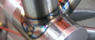
Seams using flux-cored wire turn out to be rough, with large scales, and characteristic sagging when working with an intermittent arc. A common defect is lack of penetration. Molten metal splashes are moderate. After completing the weld and removing the slag, the joint is cleaned with a metal brush.
The use of flux-cored wire allows welding work to be carried out in hard-to-reach places. Although the quality of the seam is inferior to welding in an inert gas environment, other positive aspects of this method greatly facilitate installation and construction processes.
Welding technology
Flux-cored wire grades PP-AN8, PP-AN10, PP-AN4 and PP-AN9 (Note: new generation flux-cored wire for welding in CO2: PPs-TMV-MK5, PPs-TMV7, PPs-TMV8, PPs-TMV29) is recommended for welding structures made of carbon structural steels, as well as low-alloy low-carbon structural steels of grades 09G2, 09G2S, 10G2S1, 10G2SD, 10KHSND, 15KHSND, 14G2 and a number of others.
In cases where special requirements are imposed on welded structures, the possibility of using a particular grade of flux-cored wire is determined after additional testing according to the relevant industry standards. When welding particularly critical metal structures with heavy duty operation - boilers, tanks, air heaters, load-bearing units of cars, cranes, excavators, including metal structures intended for operation in the Far North - preference is given to PP-AN4 and PP-AN9 wires, which provide higher mechanical properties of the weld metal and welded joint at negative temperatures.
Experience has shown that consumers are more willing to use PP-AN8 and PP-AN10 wires, which have higher welding and technological properties compared to PP-AN4 and PP-AN9 wires. The welding process is characterized by greater arc stability, especially at low currents. These wires also have good hygienic characteristics.
Welding with flux-cored wire with additional carbon dioxide protection is used instead of manual arc welding with coated electrodes of rutile, ore acid and calcium fluoride types, as well as instead of mechanized welding in carbon dioxide with Sv-08G2S wire.
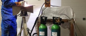
When welding, welding or food grade carbon dioxide is used, supplied in liquid form in 40 liter cylinders. The pressure in the cylinder is 50-60 ati. The weight of carbon dioxide in the cylinder is 25 kg. After evaporating it at 0 ° C and 760 Hg. Art. mm, 12600 liters of gas are formed.
Liquid carbon dioxide is also supplied in special steel containers with a capacity of up to 9 tons. At enterprises, carbon dioxide is poured into storage tanks, which are connected to a centralized main line with wiring to welding stations. This carbon dioxide delivery system is more economical than a balloon system. In addition, centralized provision of welding stations with carbon dioxide frees the welder from labor-intensive operations of replacing cylinders and moving them during the work process, and improves production standards.
The composition of carbon dioxide used for welding must correspond to the data given in table. 63 . However, in practice the content of free water in carbon dioxide can reach 2%.
Table 63
This water accumulates at the bottom of the cylinder. The humidity of the gas depends on the pressure in the cylinder. As pressure decreases, gas humidity increases. In this regard, the use of cylinders in which the carbon dioxide pressure is less than 10 atm is unacceptable. When filling a carbon dioxide cylinder, air inevitably enters and accumulates above the carbon dioxide. Therefore, before using cylinders after refueling, it is recommended to release the first portions of carbon dioxide into the atmosphere.
Reducing the ingress of moisture into the welding zone is achieved by installing desiccants filled with silica gel or other moisture absorbers along the gas path. Silica gel must be periodically calcined at a temperature of 200-250° C.
The release of gas from the cylinder is accompanied by a sharp cooling of it, which occurs due to the expenditure of heat on the evaporation of liquid carbon dioxide, which leads to freezing of the moisture contained in the carbon dioxide and clogging of the reducer. To prevent this, it is recommended to install a heater in front of the gearbox.
To reduce the gas pressure to operating pressure, reduction gears are used. The DZD-1 flow meter reduces gas pressure from 50-35 ati to a working pressure of 0.5 ati and ensures optimal gas flow. In practice, the RK-53B oxygen reducer is often used for this purpose. In this case, a pressure gauge installed on the low pressure chamber serves as a flow meter.
Gas flow is controlled by float or throttle type flow meters. When using a throttle washer installed at the gas outlet from the low-pressure chamber, the gas flow depends on the diameter of the calibration hole, which usually does not exceed 0.5-1.0 mm, and the gas pressure in the low-pressure chamber. Below is the approximate consumption of carbon dioxide depending on the readings of the low pressure pressure gauge with a hole diameter in the throttle washer of 0.8 mm.
| Pressure, atm | 0,3 | 0,4 | 0,5 | 0,6 | 0,7 | 0,8 |
| CO2 consumption, l/min | 15 | 16 | 17 | 18 | 20 | 22 |
T-, corner, lap, butt and other joints made of steel with a thickness of 3 mm and higher are welded using flux-cored wire in carbon dioxide. The position of the seams in space is lower and horizontal on a vertical plane for wire with a diameter of 2.0-2.3 mm and lower for wire with a diameter of 2.5-3.0 mm.
Welding work is recommended to be performed indoors. Welding in open areas and installations is possible provided precautions are taken to prevent the shielding gas from being blown off.
Before welding, the surface of the edges of the products being welded must be cleaned of dirt, rust, scale, and organic materials. Welding of products after gas cutting is allowed only if the cut surface is cleaned of slag.
The supplied wire must have a certificate from the manufacturer, which indicates the brand of wire, its diameter, fill factor, batch number, chemical composition of the deposited metal and the results of testing the mechanical properties of the weld metal. The use of cored wire without a certificate is not allowed. To check the quality of the supplied wire, especially in the manufacture of critical products, the consumer must carry out control tests of the wire in accordance with the requirements of the technical specifications.
Before use, wire that has been stored for a long time must be calcined at a temperature of 230-250° C for 1-3 hours. For uniform calcination, measures must be taken to prevent direct irradiation of the wire by heaters. A sign of high-quality calcination of the wire can be its color - from yellow to brown. Lack of yellowing is a sign of insufficient exposure or low temperature in the oven; the appearance of a blue color on the surface of the wire is a sign of high temperature.
Semi-automatic or automatic machines must have burners that ensure laminar flow of gas from the nozzle. When using non-standard holders, it must be taken into account that they must ensure radial gas flow from the mouthpiece relative to the wire axis.
Before passing the wire into the hose, its end must be rolled, the tip must be removed from the mouthpiece, and the hose must not have kinks. Failure to comply with these rules can lead to deformation of the wire in the rollers and failure of the hose and holder parts. After pressing with the upper rollers, the flux-cored wire should be recessed by 2/3 of the diameter into the groove of the lower rollers. The wire is passed into the hose by pressing the “start” button on the holder or feeder.
Before welding, it is necessary to set the welding mode recommended for the given wire diameter, metal thickness and type of welded joint. Adjust the gas flow according to the selected mode; wait a few seconds to completely remove air from the hoses. Set the wire extension to 35-40 mm so that the distance from the end of the wire to the nozzle exit is within 15-25 mm.
Rice. 120 . Position of the torch relative to the product when welding with unannealed wire
The arc is excited by touching the end of the wire of the product, and the wire is fed by pressing the “start” button on the holder.
The position and movement of the torch relative to the product being welded largely determine the stability of the arc, the reliability of the gas protection of the arc zone from air, the cooling rate of the metal, the shape of the seam, the intensity of torch spatter, and the ability to monitor the welding zone.
Bringing the torch closer to the workpiece makes it difficult to observe the welding process and causes clogging of the torch with spatter, and excessive removal can lead to defects in the welds due to a decrease in the effectiveness of carbon dioxide protection of the metal.
When using unheated wire, welding must be performed at an increased overhang - up to 50 mm ( Fig. 120 ).
In this case, due to the heating of the wire as it extends, the influence of moisture in the core and lubricant on the surface of the wire on the quality of the welds is reduced.
Welding butt joints or corner boat joints can be done with a “forward angle” or a “backward angle.” The angle of inclination of the wire relative to the vertical plane perpendicular to the axis of the weld should not exceed 15° ( Fig. 121 )
Rice. 121. The position of the electrode wire relative to the product when welding butt joints “backward angle” (1) and “forward angle” (2).
When welding with a “backward angle,” the penetration depth increases, the weld width decreases, more reliable protection of the metal of the weld pool is provided, and the visibility of the metal melting zone is improved. Forward angle welding is characterized by a shallow penetration depth and a large weld width. When welding single-layer seams, the torch moves translationally or in an elongated spiral. In the case of welding multilayer seams, the first layer is performed without transverse vibrations of the electrode, and subsequent layers are performed with transverse vibrations in an elongated spiral or “snake”. Welding of butt joints with deep groove is carried out with a torch with an elongated tip protruding from the nozzle by 10-15 mm. When welding fillet welds, the torch should be deviated from the vertical wall by 30-45°. Welding is done with a “backward angle” or a “forward angle”. It is recommended to perform backward angle welding at currents up to 450 A. At higher currents, better seam formation is achieved when welding with a forward angle. The burner movement is forward or reciprocating. It is not recommended to weld fillet welds in the lower position with a leg longer than 10 mm in one pass.
After stopping welding, it is not recommended to move the torch away from the weld pool until the metal has completely crystallized. When the process is stopped and continuous seams need to be made, the crater of the previous layer must be digested.
The rules of welding technique and technology outlined above apply equally to all existing flux-cored wires intended for welding in carbon dioxide. When performing certain types of welded joints, the correct assignment of the welding mode is essential. In table 64 shows the welding modes for some joints using PP-AN4 wire with a diameter of 2.2 mm.
Recommended modes for welding butt joints with PP-AN8 wire with a diameter of 2-3 mm are given in table. 65.