Electrolysis is widely used in the industrial sector, for example, to produce aluminum (apparatuses with baked anodes PA-300, PA-400, PA-550, etc.) or chlorine (Industrial units Asahi Kasei). In everyday life, this electrochemical process was used much less frequently; examples include the Intellichlor pool electrolyzer or the Star 7000 plasma welding machine. The increase in the cost of fuel, gas and heating tariffs radically changed the situation, making the idea of water electrolysis at home popular. Let's consider what devices for splitting water (electrolyzers) are, and what their design is, as well as how to make a simple device with your own hands.
What is an electrolyzer, its characteristics and application
This is the name of the device for the electrochemical process of the same name, which requires an external power source. Structurally, this device is a bath filled with electrolyte, in which two or more electrodes are placed.
The main characteristic of such devices is productivity, often this parameter is indicated in the name of the model, for example, in stationary electrolysis plants SEU-10, SEU-20, SEU-40, MBE-125 (membrane block electrolyzers), etc. In these cases, the numbers indicate hydrogen production (m3/h).
Industrial stationary electrolysis plant producing 40 m3 of hydrogen per hour (SEU-40)
As for the remaining characteristics, they depend on the specific type of device and scope of application, for example, when electrolysis of water is carried out, the efficiency of the installation is affected by the following parameters:
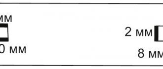
- The voltage level (minimum electrode potential), it should be from 1.8 to 2 volts; a lower value will not “start” the process, and a higher value will lead to excessive consumption of energy used to heat the electrolyte. If a power supply is used as a source, for example, 14 volts, it makes sense to divide the capacity of the bath with plates into 7 cells, in accordance with Figure 2.
Figure 2. Arrangement of plates in the electrolyzer bath
Thus, by applying 14 volts to the outputs, we will get 2 volts on each cell, while the plates on each side will have different potentials. Electrolyzers that use a similar plate connection system are called dry electrolyzers.
- The distance between the plates (between the cathode and anode space), the smaller it is, the lower the resistance will be and, therefore, more current will pass through the electrolyte solution, which will lead to increased gas production.
- The dimensions of the plate (meaning the area of the electrodes) are directly proportional to the current flowing through the electrolyte, and therefore also affect performance.
- Electrolyte concentration and its thermal balance.
- Characteristics of the material used to make electrodes (gold is an ideal material, but too expensive, so stainless steel is used in homemade circuits).
- Application of process catalysts, etc.
As mentioned above, installations of this type can be used as a hydrogen generator to produce chlorine, aluminum or other substances. They are also used as devices that purify and disinfect water (UPEV, VGE), and also carry out a comparative analysis of its quality (Tesp 001).
A) Installation of direct electrolysis of water (UPEV); B) water quality analyzer Tesp 001
We are primarily interested in devices that produce Brown's gas (hydrogen with oxygen), since it is this mixture that has every prospect for use as an alternative energy carrier or fuel additives. We will look at them a little later, but for now let’s move on to the design and operating principle of a simple electrolyzer that splits water into hydrogen and oxygen.
Hydrogen generator: its advantages and disadvantages
Today, the electrolyzer is as common a device as, for example, a plasma cutter or an acetylene electric generator. Such an electrolysis installation operating on water (stove) has become quite popular; it is used to heat private houses, and is also installed on a motorcycle or car to save fuel.
The hydrogen generator is an environmentally friendly fuel; the only waste it produces is water. It is released in a gaseous state and is known to us as water vapor. And it, in turn, does not have any negative impact on the environment.
Such a device has other positive advantages, but also disadvantages. The most important drawback is its explosiveness. However, by following all precautions and safety rules, you can avoid negative consequences.
A hydrogen reactor has its advantages:
- Powered by water;
- Saves electricity;
- Is environmentally friendly;
- High efficiency;
- Easy to maintain.
Such an HHO device can be purchased ready-made in a specialized store; it will, of course, not be cheap at all. However, you can make it yourself from available parts, saving a decent amount. However, it needs protection from water and a separate storage house.
Device and detailed operating principle
Devices for the production of detonating gas, for safety reasons, do not involve its accumulation, that is, the gas mixture is burned immediately after production. This simplifies the design somewhat. In the previous section, we examined the main criteria that affect the performance of the device and impose certain performance requirements.
The principle of operation of the device is shown in Figure 4; a constant voltage source is connected to electrodes immersed in an electrolyte solution. As a result, a current begins to pass through it, the voltage of which is higher than the decomposition point of water molecules.
Figure 4. Design of a simple electrolyser
As a result of this electrochemical process, the cathode releases hydrogen, and the anode releases oxygen, in a ratio of 2 to 1.
Homemade hydrogen generator: step-by-step instructions
Making a hydrogen generator can be done at home, but this will require drawings and step-by-step instructions for the entire process. The electrolyzer circuit is very simple (you can look it up on the Internet), so you practically won’t need any specific materials.
To create a homemade hydrogen generator, we will need some tools and materials: a plastic container or polyethylene canister with a lid, a transparent tube 1 m long, with a diameter of 8 mm, bolts, nuts, silicone sealant, a stainless steel sheet, 3 fittings, a check valve, a filter, a hacksaw metal, wrenches and knife.
Having collected all this, you can start making it. Assembly is carried out according to drawings, which can be found on the Internet or ordered from a specialist.
Manufacturing instructions:
- We cut out 16 identical plates from a stainless steel sheet.
- Drill a hole in one of the corners. The angle should be the same for all 16.
- Be sure to cut down the opposite corner.
- We install the plates one by one on the prepared bolts, insulating them with washers and polyethylene tubes. They should not contact each other.
- We tighten the entire structure with nuts, we get a battery.
- We attach this structure to a plastic container and lubricate the holes with sealant.
- We drill holes in the lid, treat them with silicone, then insert the fittings.
The homemade oxygen hydrolyzer is ready. Now it just needs to be checked for functionality. To do this, fill the container with water up to the fastening bolts and close it with a lid. We put a polyethylene hose on one of the three fittings, and lower its second end into a separate container, also filled with water. You need to connect electricity to the bolts; if bubbles appear on the surface, it means the generator is working and releasing hydrogen. After this connection and check, drain the water, and then pour the prepared alkaline electrolyte into the container to get more gas released.
Types of electrolyzers
Let's briefly look at the design features of the main types of water splitting devices.
Dry
The design of a device of this type was shown in Figure 2; its peculiarity is that by manipulating the number of cells, it is possible to power the device from a source with a voltage significantly exceeding the minimum electrode potential.
Flow-through
A simplified design of devices of this type can be found in Figure 5. As you can see, the design includes a bath with electrodes “A”, completely filled with solution and a tank “D”.
Figure 5. Design of a flow electrolyzer
The operating principle of the device is as follows:
- at the entrance of the electrochemical process, the gas together with the electrolyte is squeezed into container “D” through pipe “B”;
- in tank “D” gas is separated from the electrolyte solution, which is discharged through the outlet valve “C”;
- the electrolyte returns to the hydrolysis bath through pipe “E”.
Membrane
The main feature of devices of this type is the use of a solid electrolyte (membrane) on a polymer basis. The design of devices of this type can be found in Figure 6.
Figure 6. Membrane-type electrolyzer
The main feature of such devices is the dual purpose of the membrane: it not only transfers protons and ions, but also physically separates both the electrodes and the products of the electrochemical process.
Diaphragm
In cases where diffusion of electrolysis products between the electrode chambers is not permissible, a porous diaphragm is used (which gives such devices their name). The material for it can be ceramics, asbestos or glass. In some cases, polymer fibers or glass wool can be used to create such a diaphragm. Figure 7 shows the simplest version of a diaphragm device for electrochemical processes.
Design of a diaphragm electrolyser
Explanation:
- Oxygen outlet.
- U-shaped flask.
- Hydrogen outlet.
- Anode.
- Cathode.
- Diaphragm.
Alkaline
The electrochemical process is impossible in distilled water; a concentrated alkali solution is used as a catalyst (the use of salt is undesirable, since this releases chlorine). Based on this, most electrochemical devices for splitting water can be called alkaline.
On thematic forums, it is advised to use sodium hydroxide (NaOH), which, unlike baking soda (NaHCO3), does not corrode the electrode. Note that the latter has two significant advantages:
- Iron electrodes can be used.
- No harmful substances are released.
But one significant drawback negates all the benefits of baking soda as a catalyst. Its concentration in water is no more than 80 grams per liter. This reduces the frost resistance of the electrolyte and its current conductivity. If the first can still be tolerated in the warm season, then the second requires an increase in the area of the electrode plates, which in turn increases the size of the structure.
Welding with a hydrogen-oxygen combustible mixture from the electrolysis of water
An apparatus for gas cutting and welding of various materials, including refractory metals, would not be a problem for any household, I think. Moreover, it is compact and absolutely safe to use. But where can I get one? And many people can’t afford to buy it.
But supporters of small-scale mechanization - those who like to create everything with their own hands - probably have such a device. Perhaps even homemade, made according to sketches and taking into account the recommendations that were published on the pages of “Modelist-Constructor” (No. 7 for 1980 and No. 10 for 1985).
The next publication of the magazine tells how to make an improved version of a small-sized but quite powerful device for gas cutting and welding, working on the principle of producing a hydrogen-oxygen combustible mixture using electrolysis of an aqueous alkali solution.
I have had the first “water burner”, capable of cutting and welding even refractory metals, since 1985. I made it (and have now set up small-scale production of analogues for sale) based on materials from the “Modelist-Constructor” magazine. Now I present to the readers my latest development, which is based on, although improved (a larger number of working plates, modified side plates and a reliable fitting for the exit of a flammable gas mixture), but an electrolyser operating on the same principle.
For those who are encountering such a device for the first time, it would be useful, I think, to explain in the most general terms (and remind others) what the essence of this kind of construction is. And it's quite simple.
Fig.1. An apparatus for cutting and welding, operating on electrolysis products of a weak alkaline solution:
a - block diagram, b - finished home-made design; е - power supply unit with rectified mains voltage, 2 - electrolyzer, 3 - liquid seal, 4 - gas burner, 5 - ammeter, 6 - knob for turning on the device, 7 - knob for changing the operating mode (abrupt change in power supplied to the load), 8 - knob controls potentiometers, 9 - bracket for storing the electrical cord in a folded state, 10 - portable wooden case, 11 - plug.
Fig.2. Electrolyzer (“eighty-cell” version):
1 — side board (plywood, s12, 2 pcs.), 2 transparent cheek (plexiglass, s4, 2 pcs.), 3 — electrode plate (tin, s0.5; 81 pcs.), 4 — sealing separation ring ( 5-mm acid- and alkali-resistant rubber, 82 pcs.), 5 — insulating sleeve (cambric tube 6.2×1, L35, 12 pcs.), 6 — M6 stud (4 pcs.), 7 — M6 nut with lock washer (8 pcs.), 8 — tube for flammable gas mixture outlet, 9 — slightly alkaline solution (2/3 of the internal volume of the electrolyzer), 10 — contact terminal (refined copper, 2 pcs.), 11 — fitting (“stainless steel”) , 12 — union nut M10, 13 — fitting washer (“stainless steel”), 14 — cuff (acid- and alkali-resistant rubber), 15 — filler neck (“stainless steel”), 16 — union nut Ml8, 17 — filler neck washer ( “stainless steel”), 18 — sealing washer (acid- and alkali-resistant rubber), 19 — filler cap (“stainless steel”), 20 — sealing gasket (acid- and alkali-resistant rubber).
Between the side plates, connected by four pins, there are metal electrode plates separated by rubber rings. The internal cellular cavity of such a battery is filled with 1/2…3/4 of its volume with a weak aqueous solution of alkali (KOH or NaOH).
The voltage applied to the plates from a direct current source causes decomposition (electrolysis) of the solution, accompanied by abundant release of hydrogen and oxygen. This mixture of gases, having passed through a special liquid seal (Fig. 1a), then enters the burner and, when burned, makes it possible to obtain a high temperature so necessary for many technological processes (for example, cutting and welding of metals) - about 1800 ° C.
The productivity of the electrolyzer depends on the concentration of alkali in the solution and other factors. And most importantly, it depends on the size and number of electrode plates, the distance between them, which, in turn, is determined by the parameters of the power supply unit - power and voltage (at the rate of 2...3 V per galvanic gap between two plates located next to each other).
The designs of the direct current source I propose are available for manufacturing in a “home workshop” and for the novice DIYer. They are capable of ensuring reliable operation of even an “eighty-cell” (this one has 81 electrode plates) electrolyzer, and even more so a “thirty-cell” one.
A variant, the circuit diagram of which is shown in Fig. 4, also allows you to easily adjust the power for optimal matching with the load: in the first stage - 0...1.7 kW, in the second (when SA1 is turned on) - 1.7...3.4 kW.
And the corresponding plates for the electrolyzer are offered - 150x150 mm. They are made from roofing iron 0.5 mm thick. In addition to the 12-mm gas outlet hole, four more mounting holes (2.5 mm in diameter) are drilled in each plate, into which knitting or bicycle needles are threaded during assembly.
The latter are needed for better centering of the plates and gaskets, and therefore are removed from the structure at the final stage of assembly.
Actually, I had to rack my brains a lot before the “water burner” became convenient and reliable, like an Edison lamp: turn it on and it started working, turn it off and it stopped working. A particularly troublesome task was the modernization not of the electrolyzer itself, but of the liquid seal connected to it at the output. But as soon as we abandoned the routine use of water as a barrier against the spread of flame inside the gas-forming battery (through the connecting tube) and turned to the use of... kerosene, everything immediately went smoothly.
Why was kerosene chosen? Firstly, because, unlike water, this liquid does not foam in the presence of alkali. Secondly, as practice has shown, if drops of kerosene accidentally fall into the burner flame, the flame does not go out - only a small flash is observed.
Finally, thirdly: being a convenient “separator”, kerosene, when in the seal, turns out to be safe in terms of fire.
Fig.3. Kerosene seal and the principle of its operation (a - when the electrolyzer is running, b - when the device is turned off): 1 - cylinder (2 pcs.), 2 - plug (2 pcs.), 3 - input fitting, 4 - output fitting, 5 - kerosene, 6 - adapter (steel pipe).
At the end of work, during a break, etc. the burner naturally goes out. A vacuum is formed in the electrolyzer, and kerosene flows from the right tank to the left (Fig. 3).
Then - air barbation, after which the burner can be stored as long as you like: it is ready for use at any time. When it is turned on, the gas presses on the kerosene, which again flows into the right tank. Then gas bubbles begin...
The connecting tubes in the device are polyvinyl chloride. Only a thin rubber hose leads to the burner itself. So, after turning off the power, it is enough to bend this “rubber” with your hands - and the flame, finally giving out a light pop, will go out.
Fig.4. Schematic diagram of the power supply unit.
And one more subtlety. Although the power supply (see Fig. 4) is capable of providing electricity to a 3.4-kilowatt load, using such high power in amateur practice is very rare.
And in order to “not drive the electronics” almost empty (in half-wave rectification mode, when the output is 0...1.7 kW), it is useful to have at your disposal another power source for the electrolyzer - smaller and simpler (Fig. 5). In essence, this is a full-wave adjustable rectifier, known to many DIYers.
Moreover, with “engines” of 470-ohm potentiometers connected to each other (mechanically). Structurally, such a connection can be achieved either using a simple gear transmission with two textolite gears, or using a more complex device such as a vernier (in a household radio).
Fig.5. A power supply option using thyristors and a homemade transformer in the circuit.
The transformer in the power supply is homemade. A set Ш16×32 made of transformer steel was used as a magnetic core. The windings contain: primary - 2000 turns PEL-0.1; secondary - 2×220 turns PEL-0.3.
Practice shows: the considered homemade apparatus for gas cutting and welding, even with the most intense use, is capable of serving properly for a very long time. However, thorough maintenance is required every 10 years, mainly due to the electrolyser.
The plates of the latter, working in an aggressive environment, are covered with iron oxide, which begins to act as an insulator. The plates have to be washed and then sanded using an emery wheel. Moreover, replace four of them (at the negative pole), corroded by acidic residues that accumulate near the “minus”.
Therefore, it is recommended to fill the electrolyzer only with distilled water, and to use an alkaline solution that is least contaminated with salts (the presence of traces of chemical compounds of sulfuric and hydrochloric acids is unacceptable).
The use of so-called drain holes (except for the filler and gas outlet) can also hardly be considered justified, which was taken into account when developing the device. It is equally optional to introduce cans into the apparatus circuit to collect the accumulating super-aggressive alkali.
In addition, the operation of the “tankless” design shows that no more than half a glass of this “harmful liquid” can accumulate at the bottom of a kerosene seal over a 10-year period. The accumulated alkali is removed (for example, during maintenance), and the next portion of clean kerosene is poured into the shutter.
V. RADIKOV, Tatarstan. Modeler-constructor 1997 No. 3.
Electrolyzer for hydrogen production: drawings, diagram
Let's look at how you can make a powerful gas burner powered by a mixture of hydrogen and oxygen. A diagram of such a device can be seen in Figure 8.
Rice. 8. Hydrogen burner design
Explanation:
- Burner nozzle.
- Rubber tubes.
- Second water seal.
- The first water seal.
- Anode.
- Cathode.
- Electrodes.
- Electrolyzer bath.
Figure 9 shows a schematic diagram of the power supply for the electrolyzer of our burner.
Rice. 9. Electrolysis torch power supply
For a powerful rectifier we will need the following parts:
- Transistors: VT1 – MP26B; VT2 – P308.
- Thyristors: VS1 – KU202N.
- Diodes: VD1-VD4 – D232; VD5 – D226B; VD6, VD7 – D814B.
- Capacitors: 0.5 µF.
- Variable resistors: R3 -22 kOhm.
- Resistors: R1 – 30 kOhm; R2 – 15 kOhm; R4 – 800 Ohm; R5 – 2.7 kOhm; R6 – 3 kOhm; R7 – 10 kOhm.
- PA1 is an ammeter with a measurement scale of at least 20 A.
Brief instructions on parts for the electrolyzer.
A bathtub can be made from an old battery. The plates should be cut 150x150 mm from roofing iron (sheet thickness 0.5 mm). To work with the power supply described above, you will need to assemble an 81-cell electrolyzer. The drawing for installation is shown in Figure 10.
Rice. 10. Drawing of an electrolyzer for a hydrogen burner
Note that servicing and managing such a device is not difficult.
DIY electrolyzer for a car
On the Internet you can find many diagrams of HHO systems, which, according to the authors, allow you to save from 30% to 50% of fuel. Such statements are too optimistic and, as a rule, are not supported by any evidence. A simplified diagram of such a system is shown in Figure 11.
Simplified diagram of an electrolyzer for a car
In theory, such a device should reduce fuel consumption due to its complete burnout. To do this, Brown's mixture is supplied to the fuel system air filter. This is hydrogen and oxygen obtained from an electrolyzer powered from the car’s internal network, which increases fuel consumption. Vicious circle.
Of course, a PWM current regulator circuit can be used, a more efficient switching power supply can be used, or other tricks can be used to reduce energy consumption. Sometimes on the Internet you come across offers to purchase a low-ampere power supply for an electrolyzer, which is generally nonsense, since the performance of the process directly depends on the current strength.
This is like the Kuznetsov system, the water activator of which is lost, and the patent is missing, etc. In the above videos, where they talk about the undeniable advantages of such systems, there are practically no reasoned arguments. This does not mean that the idea has no right to exist, but the declared savings are “slightly” exaggerated.
DIY electrolyzer for home heating
At the moment, it makes no sense to make a homemade electrolyzer for heating a house, since the cost of hydrogen obtained by electrolysis is much more expensive than natural gas or other coolants.
It should also be taken into account that no metal can withstand the combustion temperature of hydrogen. True, there is a solution, patented by Stan Martin, that allows you to circumvent this problem. There is a key point to pay attention to that allows you to distinguish a worthy idea from obvious nonsense. The difference between them is that the first is issued a patent, and the second finds its supporters on the Internet.
This could be the end of the article about household and industrial electrolyzers, but it makes sense to make a short overview of the companies producing these devices.