Fusion welding when joining such metals is extremely difficult. This is because the composition of the molten metal is almost impossible to control. And the properties of the weld depend on the copper content in its composition.
If the amount of copper is higher than 12%, then the tensile strength is no longer increased. At the same time, the corrosion resistance and viscosity of the metal is greatly reduced. Such connections become quite fragile and prone to defects.
The use of carbon electrodes has virtually no effect and does not improve the quality of welding. These metals can be joined by melting, but only if the melting is primarily an aluminum part. Where possible, a “lock” connection is predominantly used. Read about it below.
Difficulties in fusion welding of aluminum and copper products
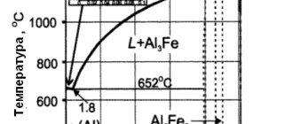
It is quite difficult to weld copper to aluminum using fusion welding. This happens due to the fact that the composition of the molten metal is almost impossible to regulate, and the mechanical properties of the welded joint strongly depend on the copper content in it, this is clearly visible from the diagram (see figure on the left).
If the copper content in a copper-aluminum alloy exceeds 12%, then the tensile strength stops increasing, and the toughness of the alloy and its corrosion resistance drop sharply. Therefore, when the copper content in the weld metal is more than 12%, the joint becomes very brittle and prone to cracking after welding.
Practical studies on welding aluminum and copper using a carbon electrode have not yielded positive results. It is possible to join copper and aluminum using fusion welding if the material being melted is predominantly aluminum. The so-called “lock” connection is often used, where possible.
"Lock" connection between aluminum and copper
The essence of the “lock” connection (see figure on the left) is as follows. A copper plate, item 2, is placed on the aluminum sheet, item 1, and it is welded around the entire perimeter, flush with the plate. Next, surfacing is performed, position 3, which connects the welds deposited along the perimeter of the copper plate. This creates something like an aluminum alloy lock. The welding process must be carried out with forming graphite strips.
Welding modes for aluminum and copper
The welding modes for aluminum and copper are very similar to the welding modes for aluminum. The nature of the welding current is constant, straight polarity. Cast aluminum rods with a diameter of 12-20mm for a thickness of aluminum of 29-30mm and copper of 10mm are used as filler material. Welding current strength is 500-550A. The electric arc voltage is 50-60V, and its length is 20-25mm. For welding, graphite electrodes with a diameter of 15-20 mm are selected.
Problems with soldering aluminum
Aluminum oxide (Al2O3) in mineralogy is called corundum Source masterpaiki.ru
Most people who are friends with a soldering iron have tried to solder aluminum at least once in their lives and were convinced that it is almost impossible even after tinning with hydrochloric acid. But why is that? A film of aluminum oxide (Al2O3), which appears immediately after stripping, resists good contact with tin. This suggests that you first need to limit the possibility of the formation of an oxide film and only then start soldering - there is no other way.
Notably, aluminum oxide is a gemstone known as corundum. Depending on the impurity content, corundum can be red (with impurities of Cr), known as ruby, or blue, with impurities of iron (Fe) and titanium (Ti), known as sapphire. That is, solder cannot have adhesion to a stone, even a precious one.
Resistance welding of aluminum and copper
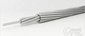
Resistance welding of aluminum-copper joints is successfully used in the electrical industry for welding aluminum busbars with copper tips, and aluminum wires with copper tips. In the cable industry, capacitor welding of aluminum and copper wires is widely used according to the modes indicated in the table below:
| Capacitor voltage, V | Distance between parts, mm | Upsetting force, N | ||
| 2,5 | 256 | 1100 | 14 | 1471 |
| 2,8 | 256 | 1400 | 10 | 1471 |
| 2,8 | 260 | 1400 | 15 | 1471 |
| 2,8 | 380 | 1350 | 15 | 1569 |
| 2,8 | 550 | 1200 | 15 | 1716 |
| 3,5 | 550 | 1500 | 12 | 1569 |
| 5,0 | 1000 | 1500 | 14 | 1716 |
Welding modes
They are very similar to aluminum welding modes. During processing, direct current of straight polarity is used. Filler rods are products made of cast aluminum with a diameter from 12 to 20 millimeters with a thickness of the aluminum part from 29 to 30 millimeters. The thickness of the copper product is 10 millimeters. The current strength is allowed in the range of 500-550 amperes, and the arc voltage is 50-60 volts. Its length ranges from 20 to 25 millimeters. The optimal electrodes in this case are carbon electrodes with a diameter of 15-20 millimeters.
Inverter devices
The most reliable type of connecting electrical wires is welding using direct and alternating current, voltage from 12 to 36 V. For welding, electricians are increasingly using inverter welding machines. They are economical, lightweight, easy to carry and use. To weld wires, you can use graphite or simple carbon rods from a battery. You can set the current mode on the device, taking into account the diameter and number of wires being welded
How to choose a device
Preference is given to a welding inverter. Its main advantages are: wide range, the ability to softly regulate current, stability in operation, small size and weight.
For welding wires, you can choose a universal inverter machine. This device is the most modern. With this device you can perform all kinds of welding, and not just wires. When choosing a device, you need to look at the power source and its power. For work at home, a device with a power of 4 - 5 kW, with a current strength of up to 160 A, is suitable. It is advisable to have a “hot start”. It is needed to protect against sticking during welding and voltage surges. Such a device is useful for welding wires and for performing other welding work at home. Another advantage is that it is easy to use and does not require great skills. The disadvantages include its high price.
In practice, electricians use compact, portable, easy-to-use DC machines for welding wires. Welding transformers are compact and inexpensive. Transformers with a power of 500 W or more and 25 V secondary voltage can be used.
DIY wire welding machine
Do you want to make a wire welding machine? Don't know how? It's done like this. Purchase a strong magnet and copper wire insulated with fiberglass or cotton. It is needed for the transformer core. It is desirable that its cross-sectional area is no more than 50 square centimeters. If desired, you can also do the wire wrapping yourself. The required material is taken, wound on a wire, coated with electrical varnish and the primary winding is ready. The core is made in a U-shape for convenient winding of wire. It must have a rod structure. The reel frame can be made of PCB or cardboard. The secondary winding is wound on top of the primary winding. After applying the winding to one side of the coil, it is applied in the same way to the other half. If you place cardboard or fiberglass between the layers of the winding, the quality of the insulation will improve. A copper wire welding machine is connected to the network to measure the voltage on the secondary winding. It should be about 60 V. If it is much more or less, then by decreasing or increasing the winding, you can set the desired voltage value. A cable is connected to the primary winding. It must be two-wire. Instead, you can use an internal wire. A PRG wire is connected to the terminals of the secondary winding. The primary winding is used to receive current from the mains at 220 W through the cable. The secondary winding is used directly for welding.
Anyone who has at least once encountered the need to connect wires during electrical installation work knows how responsible the approach to this matter must be. The main task is to minimize the transient electrical resistance that occurs between the contacting conductors.
As you know from a physics course, the weaker the contact, the more the conductors heat up due to increased resistance. Therefore, it is necessary to achieve the most durable, almost monolithic, connection of electrical wires. This is a prerequisite for reliable and safe operation of electrical installations.
Connection with spring and self-clamping terminal blocks
Currently, both reusable and single-use terminal blocks and terminal blocks are produced.
- spring terminal blocks and reusable terminal blocks have a retaining spring that can be loosened by lifting a lever located on the device body. This allows you to remove or insert the wire without any effort. Lowering the lever securely fixes the cable cores;
- Single-use terminal blocks automatically clamp the wire when inserting it into the socket; removing the wire will require physical force, which can damage the clamping spring, so their single use is recommended.
Both reusable and single-use terminal blocks are produced in a wide range, including with a different number of connected wiring branches, designed to fix wires with a cross-section from 0.08 mm² to 6 mm². Including in the form of ready-to-install terminal boxes. This method of connecting aluminum and copper wires is currently the most optimal in terms of reliability and ease of use.
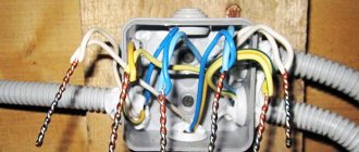
Section of the spring terminal block and placement of the connection in the junction box
Terminal boxes with spring clamps were first produced by the German company Wago, from which they got their name, but currently there are a large number of analogues, including counterfeit ones. For this reason, it is necessary to purchase spring terminal boxes only from electrical stores. When purchasing terminal boxes on the market, there is a high probability of purchasing low-quality products that do not meet the stated requirements.
Self-clamping terminal block WAGO
To fix the wires in the terminal box, it is necessary to prepare the wires; to do this, remove the insulation from their ends; the size of the exposed part must be at least 0.5 cm. After that, the open part of the cable core is inserted into the desired socket of the terminal box and fixed in it using a spring clamp or screw. It should be noted that mounting in a terminal box usually does not require additional insulation, but at the same time, when they are located in a wall, a distribution box is required. Thus, spring terminal blocks have a number of advantages over other types of connections due to ease of connection.
Self-clamping terminal block
Process technology
Welding methods for non-ferrous metals are selected in accordance with their physical and chemical properties. When choosing a method, take into account the presence of:
- necessary equipment;
- welding materials.
The economic and technical feasibility of the method and the qualifications of technologists and welders are also taken into account.
Table of welded non-ferrous metals and types of welding used.
| Name of metal | Dugovaya | Argon-arc | Electroslag | Electron beam in vacuum | Gas |
| Aluminum | + | + | + | + | |
| Magnesium | + | + | |||
| Copper | + | + | + | ||
| Nickel | + | + | + | ||
| Titanium | + | + | |||
| Tantalum | + | + | |||
| Zirconium | + | + | |||
| Hafnium | + | + | |||
| Molybdenum | + | + | |||
| Tungsten | + | + | |||
| Niobium | + | + | |||
| Zinc | + | + | |||
| Silver | + | + | |||
| Vanadium | + | ||||
| Lead | + | + | + |
Properties of non-ferrous metals
Non-ferrous metals are practically never found in their pure form, but alloys made from them are in demand. The main areas of application of such alloys in industry are aviation, automotive, chemical and food industries. At home, copper, aluminum, nickel and other substances are most often used for welding.
When carrying out welding work on non-ferrous metals and alloys, it is necessary to take into account their characteristics, type of welding and other nuances:
- Oxidation. Non-ferrous metals and alloys made from them are highly susceptible to the influence of oxygen, which is why an oxide film subsequently forms on their surface. This film prevents a strong connection and provokes the formation of cracks in the seam.
- Thermal conductivity. It manifests itself in the rapid cooling of the surfaces being welded. For a high-quality connection, preheating of the parts or sources of strong heat will be required.
- Melting temperature. There are metals that have different melting points with alloys, and therefore there is a high probability of evaporation of the “light” element. Speeding up the process will help avoid this.
- Loss of strength. During the heating process, non-ferrous metals can be destroyed by weak external influences. You must work with such substances with extreme caution.
- Interaction with the environment. Due to the characteristics of these metals and their alloys, welding should be performed exclusively in a shielding gas environment to achieve the required result.
Taking into account these nuances, you should not neglect the pre-treatment of parts for welding, namely the removal of oxides from the surface and degreasing the edges of the joint.