material provided by Ph.D. TOLSTYKH Leonid Grigorievich
in collaboration with TOLSTYKH A.L.
High-performance installations have been developed for applying wear-resistant, heat-resistant and corrosion-resistant metal layers 0.01-0.80 mm thick with a productivity of up to 40 cm2/min. Some features of ESA with high-speed steel have been studied.
It is known that for electric spark alloying
(EAL), refractory metals, hard alloys and, less commonly, heat-resistant high-alloy steels and alloys with high mechanical properties are widely used []. In many cases, the reason for this is the difficulties of the ESA process associated with “sticking” of the anode when using a vibrator. In our opinion, the main reasons for “sticking” are:
- insufficient energy of a single discharge pulse;
- high strength of the applied material;
- high melting point of the material;
- insufficient vibrator power;
- non-optimal speed of movement of the vibrator over the workpiece.
To expand the capabilities of ESA both in terms of increasing the range of use of various metals, alloys and materials, and in order to increase the productivity of the ESA process, the thickness of the applied layer, increasing its density (reducing porosity) while simultaneously simplifying the ESA process at the Ural Federal University (Ekaterinburg) INTAL-1500 were developed
and
INTAL-3000
(Table 1).
Table 1 - Technical characteristics of installations for ESP
| Parameter name, dimension | INTAL-1500 | INTAL-3000 |
| Supply voltage, V | 220 | |
| Maximum primary current, A | 15 | |
| Capacity of the capacitor bank, µF | 1500 | 3000 |
| Capacitor charging voltage, V | 20-115 | |
| Pulse energy, J | 0,3-10,5 | 0,4-21,0 |
| Pulse repetition frequency, Hz | 30-400 | 15-200 |
| Installation efficiency | 0,90 | 0,92 |
| Dimensions, mm | ||
| length | 550 | 650 |
| width | 300 | 400 |
| height | 500 | 550 |
| Weight, kg | 28 | 37 |
| Coating system | vibration-free, rotary | |
| Coating Device | rotator | |
The installations are created on a new (modern) element base with a total constant capacity of 1500 and 3000 μF, with a smooth change in voltage and charging current of a battery of capacitors, that is, adjustment of energy parameters, such as discharge energy and the frequency of these discharges. The pulse energy varies from 0.3 to 21.0 J, and the frequency from 30 to 400 Hz. In this case, the charge voltage of the capacitors varies from 20 to 115 V, and the current from 3 to 25 A.
Figure 1 shows the dependence of the energy of a single pulse on the charging voltage of the capacitors. It is determined from the expression E = CU2/2
.
The pulse energy E
depends only on the selected voltage value
U
, since the capacitance of the capacitors
C
in the 1500 and 3000 mF settings is constant and cannot be adjusted.
Figure 1 - Dependence of the energy of a single pulse on the voltage on the capacitors
If you change the charging current of the capacitors, the frequency of the charging and discharging pulses of the capacitors will change. In most installations for ESA, the pulse repetition rate is related not only to the set mode parameters (charging voltage of capacitors and their capacitance), but also to the presence (or absence) of contact of the electrode (anode) with the product (cathode) which is created by the vibrator. Vibrators most often operate at an industrial frequency of 50 Hz, so the pulse frequency is usually constant and only ideally reaches 100 Hz.
In the described installations INTAL-1500 and INTAL-3000, any frequency can be selected in the range from 30 to 400 Hz, based on the tasks being solved. In this installation, the pulse repetition frequency is free, as in the master oscillator, that is, it depends only on the set voltage and charging current of the capacitors and does not depend on the presence or absence of contact of the electrode with the product. This allows you to abandon the use of a vibrator and move the electrode over the product being hardened by rotating the disk or cylindrical electrode. Since the electrode is in constant contact with the product, the process of metal transfer changes and its oxidation decreases, the applied metal is more dense, without pores, and the surface roughness does not deteriorate with an increase in the number of layers.
The installations use an inverter converter, which made it possible to increase the efficiency of the installations and significantly reduce their dimensions and weight. The units have a soft start system after being plugged into a 220 V network. The primary current from the network does not exceed 15 A, so they can be plugged into a regular outlet.
Since the installation is an energy-stressed device (due to its small dimensions and weight), to ensure normal temperature conditions for power semiconductor devices, forced ventilation is used and overheating protection is introduced, blocking the operation of the installations in unacceptable thermal conditions.
Figure 2 shows the dependence of current on voltage for pulse repetition rates that are multiples of 50 Hz. From Figure 2 it is clear that higher frequencies can be obtained only at voltages less than 70 V, that is, in softer modes with average pulse energy. With a discharge energy close to the maximum, at a voltage of 110 V, the frequency does not exceed 150 Hz.
Figure 2 - Dependence of current on voltage for frequencies 50-400 Hz
If we draw a line for a voltage of 60 V (or any other), parallel to the abscess (current) axis, then at its intersection with the frequency lines 50, 100, 150, 200, 300, 400 we get the current value that needs to be set to obtain any of these frequencies. In the INTAL-3000 installation, the pulse repetition rate at the same capacitor charging current as the INTAL-1500 installation is 2 times lower.
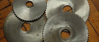
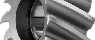
To apply the coating, a disk with a diameter of 20-200 mm and a width of 3-5 mm, or a cylindrical rod with a diameter of 2-10 mm and a length of up to 150 mm is used as an anode. The rotation speed of the disk is 2 r/s, the rod is 5 r/s. The coating is applied without vibration.
Using these installations, the process of applying high-speed steel P18 was studied. ESA was performed on samples made of low-alloy steel 20ХН2 with dimensions of 70×20×10 mm at various voltages for 1 min. The anode - a disk made of high-speed steel, the cathode - a sample of steel 20ХН2 were weighed before and after ESA on an analytical balance with an accuracy of 1 mg. Anode erosion and cathode weight gain are shown in Figure 3 in absolute values without taking into account their sign (minus for the anode and plus for the cathode). The absolute difference between erosion and gain is the irreversible loss of applied material.
Figure 3 - Effect of current (frequency) on anode erosion and cathode weight gain
In particular, Figure 3 shows the effect of current (frequency) on anode erosion (curve 1) and cathode weight gain (curve 2) at a constant voltage of 80 V. The voltage of 80 V was chosen because it is average for this installation and, in addition, , allows you to explore almost the entire range of currents (frequencies) at which the installation can operate.
As can be seen from Figure 3, anode erosion with increasing current from 6.1 A (frequency 50 Hz) to 24.4 A (frequency 200 Hz) changes almost linearly from 180 to 580 mg. The increase in cathode weight at currents from 6.1 to 18.3 A (frequencies 50 and 150 Hz, respectively) also increases linearly. In the area from 18.3 to 24.4 A, the gain decreased, which is apparently due to overheating of the sample due to its insufficient mass; with an increase in current, the erosion and gain curves diverge, which indicates that anode losses increase.
Figure 4 shows the effect of voltage (discharge energy) on anode erosion (curve 1) and cathode weight gain (curve 2). From Figure 4 it can be seen that the erosion and weight gain curves in the 60-100 V section are almost equidistant and slightly increasing. In the region from 100 to 115 V, a sharp increase in anode erosion is observed with a moderate increase in cathode weight gain. Most likely, the increased erosion of the cathode is explained by its heating to 500-550 °C due to the high current and small size of the cathode and the lack of cooling. The tendency for the cathode gain to increase with increasing voltage (pulse energy), in our opinion, is favorable, since it helps to increase the productivity of the process and the application of a thicker coating layer.
Figure 4 - Effect of voltage on anode erosion and cathode weight gain
As follows from the expression E = CU2/2
, the energy of a single pulse to increase the productivity of the ESA process can be increased both by increasing the charging voltage of the capacitors and by increasing the capacity of the capacitor bank. A further increase in voltage is undesirable for safety reasons, and therefore we had to double the capacitance of the capacitor bank to 3000 mF to increase the energy of a single pulse.
Figure 5 shows the effect of single pulse energy on anode erosion and cathode weight gain for P18 high-speed steel.
Figure 5 — Effect of single pulse energy on anode erosion and cathode weight gain
As can be seen from Figure 5, increasing the energy of a single pulse from 10 J (INTAL-1500 installation) to 20 J (INTAL-3000 installation) made it possible to increase anode erosion from 460 to 1300 mg, that is, 2.82 times, and the cathode weight gain increased from 270 to 610 mg, that is, 2.26 times. The efficiency factor for the use of erodible material decreased from 0.58 to 0.47, that is, the loss of erodible material increased by 1.23 times, which, in our opinion, is quite acceptable.
It is known that the parameters of the ESA mode, and in the general case, the pulse energy (power) affect not only the thickness of the applied layer, but also the depth of the heat-affected zone (HAZ) []. In order to clarify the influence of the capacitor charging current at a constant charging voltage (U = 100 V) on the HAZ depth, we conducted the following experiment. ESA was performed using high-speed steel on samples measuring 70×20×5 mm from annealed U11 steel. The capacitor charging current was 10, 15, 20 and 25 A at a voltage of 100 V, the ESA time was 1 min. After ESA, transverse sections were made from the samples to measure microhardness using a PMT-3 microscope at a load of 200 g. Microhardness measurements were made in increments of 50 μm. The measurement results are shown in Figure 6.
Figure 6 - Effect of single pulse energy on anode erosion and cathode weight gain
As can be seen from Figure 6, with an increase in the charging current of capacitors from 10 to 20 A, the microhardness at a distance of 50 μm increases from 16000 to 19500 MPa, and an increase in current to 25 A leads to a decrease in microhardness to 17000 MPa, which is most likely due to that significant heating of the sample occurs, causing a decrease in the cooling rate of the applied layer and the HAZ. Increasing the current from 10 to 25 A leads to an increase in the strengthened layer together with the HAZ from 200 to 450 μm. In this case, the increase in the strengthened HAZ is an additional advantage when increasing the power during ESA.
The appearance of one of the transverse sections with punctures in the applied layer, the ETV and the base metal is shown in Figure 7. The boundary between the strengthened HAZ and the base metal is easily distinguished both by hardness (the size of the indentations) and by the different etchability of the surface of the transverse section.
Figure 7 — Cross-section of a sample with punctured marks
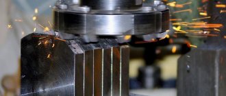
The essence of the method
The idea is based on the transfer of small portions of material when plasma discharges occur. The operation of melting and deposition of the alloy takes place in an air-gas environment. The method resembles a micro-welding process.
The occurrence of a short-term electrical pulse causes the melting of the alloying base of the electrode and its transfer to the surface being treated. Hence, another name for the process is “electric spark coating”, “electric spark hardening”.
Tool hardening
It was assumed that ESA would be widely used to increase the durability of tools made of carbon, alloy and high-speed steels to the level of tools made of expensive sintered hard alloys. But this did not happen. The use of ESA for tool hardening can be characterized as sporadic. This is probably due to its low productivity and predominantly manual application. In addition, ESL coatings create high slip resistance. They are formed by welding small portions of metal, each of which forms sharp, hard edges, so that the resulting surface of the part is likened to sandpaper. To eliminate this effect, some ESA installations provide a vibration mode for the electrode without current pulses to smooth the surface by striking a ball fixed in the vibration holder instead of the electrode. This increases labor intensity, but does not always bring the expected effect. Therefore, it is preferable to harden using the ESA method over surfaces operating under conditions of rolling friction or having fixed contact. The experience of the Salda Metallurgical Plant is indicative. It has been there since the 1980s. matrices for flashing holes in rail pads process ESA only along the end (support) surface, which is in fixed contact during operation. The inner surface on which the punch (punch) and the cut metal slides is left without ESA hardening. This increases the durability of the matrices by 1.5–2.0 times. The PELM company, which produces specialized installations for electrospark alloying UR-121 for cutting tools, reports that the durability of woodworking tools (frame, band, circular, chain saws, planing knives, planers, thickness planers) increases up to 6 times [3]. But the author is not yet aware of the regular use of this installation for hardening metal-cutting tools. The roughness of the coating applied when using it is ~ Ra5, which is significantly greater than the typical cleanliness of cutting edges and, apparently, interferes with obtaining a stable positive effect. However, there is still one case of unconditional success. The task was to drill out the rivets holding the blades in the supercharger impeller, which were welded with a welding electrode and thus hardened. More than a dozen drills were dulled, but not a single rivet was drilled out. Things moved forward only after the drills, after sharpening, began to be hardened using the UR-121 installation.
Advantages
The surface hardening method has been developed due to a number of consumer properties:
- the ability to carry out targeted impact on an area not exceeding fractions of a millimeter; no protection of the surrounding surface is required;
- ensuring reliable contact of the applied ligature with the main surface of the workpiece - high degree of adhesion; explained by the fact that during the process partial diffusion (penetration) occurs deep into the metal;
- the appearance of a small thermal background; as a result, there is no heating of the surface and no deformation of the product occurs;
- simple technological process; no special surface preparation required;
- energy intensity does not exceed 2 kW;
- the equipment has small overall dimensions and weight, therefore, it is transportable as hand luggage;
- high efficiency - mass transfer of metal is in the range of 60-80%.
Electric marker for metal. How to make an engraving?
Specific methods of electric spark processing of conductive materials include engraving their surface using a low duty cycle electric discharge. Metal electric markers produced for these purposes are compact, energy-saving devices, and therefore are widely used for both industrial and domestic purposes.
Device characteristics
When the interelectrode gap between the cathode, which is a marking tool (sometimes called an electrographic pen) and the anode, the metal surface, breaks down, erosion of the anode metal occurs, as a result of which a set of holes is formed.
Their shape and location are determined by the trajectory of the electric marker across the metal and the intensity of the electrical impulse.
In order for the thermal energy of metal evaporation to be concentrated in a limited volume, the surface of the processing zone is wetted with a liquid dielectric, which uses ordinary mineral oil.
In addition, the oil reduces the force of separation of a manually moved electrode from the surface being treated, preventing a short circuit in the interelectrode gap. The anode blank is connected to the general electrical circuit of the device using a clamp. You cannot use water for electrical marking, and especially not aqueous solutions of salts.
As a result of point erosion, a pattern, production mark or any other mark up to 1...2 mm deep can be formed on the surface. In addition, the marked surface is visually different.
Since the result of a single act of electrical erosion is a hole where the bottom is formed by periodic electrical impulses, the treated surface is always matte, and therefore is especially noticeable on ground, polished or cold-rolled metal.
The electrographic marking process runs stably with the following operating characteristics of the device:
- Operating voltage, V – 30…140.
- Processing current, mA – 40…300.
- Duty cycle, s-1 – up to 100.
- The cathode material is tungsten wire with a diameter of up to 1 mm (it is also possible to use high-carbon steel type 65G or 60S2).
In practice, the power consumption of the device depends on the marking depth and the electroerosive ability of the anode metal, but usually does not exceed 20...50 W.
The delivery set also includes a vibrator that generates vibrations of the working head of the device with the required frequency.
In order to ensure electrical safety, electric markers for metal are equipped with thermal sensors that respond to overheating.
Operating principle of an electric marker
The metal surface to be marked must be thoroughly cleaned of grease and oxide films.
The latter noticeably worsen the conductivity of the metal, which forces an increase in the voltage in the interelectrode gap.
The discharge results in a low duty cycle, but with coarser dimples, which deteriorates the quality of marking. The spark discharge power is controlled by a step switch.
The following geometric characteristics of the hole are considered optimal for these purposes:
- Width – 0.2…2.0 mm;
- Depth – 0.15…20 µm;
- The speed of marker movement on the surface is up to 10 mm/s.
The kit of some models of electric markers for metal also includes a steel plate, equipped with fasteners for fixing the part that is being marked.
The sequence of working with an electric marker for metal is as follows. The device is connected to a household power supply with a voltage of 220 V and a frequency of 50 Hz through an autonomous power supply. The part to be marked is attached to a metal plate using an alligator clip.
In order to protect the operator’s eyes, the vibration device is covered with a special filter, after which the electrographic pen is brought to the surface, which is covered with a thin (2...3 mm) layer of liquid dielectric.
First, a test discharge is performed, during which the optimal speed of movement of the electrographic pencil along the surface of the product is established. As the pen moves, new processing areas are wetted with the dielectric.
To set up an electrographic marker for metal, you must perform the following steps:
- Set the vibrator frequency to the required mode. To do this, use (depending on the size and manufacturer of these devices) one of the following methods: either optimize the sound signal (as the oscillation frequency decreases, the permissible value of the interelectrode gap increases), or adjust the frequency by changing the brightness of the signal light.
- The switch sets the required current value. It is usually maximum for metals with low thermal conductivity (most non-ferrous metals and alloys), and less for aluminum, steel or cast iron.
- By moving the electrode-tool along the required trajectory of movement, marking is made. The overall dimensions of the symbols have no restrictions.
- When working with an electric marker, it should be remembered that increasing the voltage and current of the electrical discharge beyond the required speeds up the wear of the electrode and does not lead to a significant increase in the productivity of the process. Wear is especially intense in the event of a short circuit (occurs when there is a lack or absence of dielectric fluid on the marked surface of the product). For guidance, you can use standard wear values of 0.05...0.2 mm per mark.
- To correct an erroneously applied mark, the surface must be sanded.
The use of an electric pencil requires the operator to have certain skills and experience.
The duration of continuous use of an electric spark marker is not fundamentally limited, although if the device operates for more than 30...40 minutes, the pulse generator unit warms up.
Replacement of a worn cathode-tool is carried out with the device turned off. The electric metal marker should not be used in rooms where the relative air humidity exceeds 75%.
Advantages of electric markers and their standard sizes
Preservation of the marketable appearance of products after electrical marking is ensured by:
- No distortion of the product surface;
- The ability to brand thin surfaces without the risk of deforming them;
- Effective use of the process regarding any conductive materials;
- Convenience of applying brands, the range of which is not limited in any way;
- When using a tungsten electrode with selective metal transfer, anti-corrosion treatment of the surface of steel products is simultaneously carried out.
Models of the most popular electric markers are shown in the table
| Device model | Overall dimensions of the hole, microns | Limit character size, mm | Voltage, V | Current, mA | Power consumption, W | Company, country | Approximate price, rub. |
| EVZ-021 | 10×10 | Up to 50 | 220…230 | 200 | 20 | Josef Solnar (Czech Republic) | 10000 |
| EVZ-022 | 20×50 | Is not limited | 220…230 | 450 | 50 | Josef Solnar | 12000 |
| AG25/3 | 20×20 | Same | 4 | 5000 | 25 | ArgloAG (Switzerland) | 23500 |
| AG50/6 | 20×50 | Same | 6,5 | 6500 | 50 | ArgloAG | 25000 |
Application
Electrospark alloying has found application in the fields of mechanical engineering and metalworking:
- automobile production;
- general mechanical engineering;
- production of technological equipment;
- processing of dies for heat treatment of metals;
- increasing the cutting properties of the processing tool;
- hardening of gear teeth;
- increasing the wear resistance of crankshaft journals and other applications;
- repair operations to restore the functionality of damaged parts.
Due to the localization of the processing area, the method of electric spark hardening is used by watchmakers and jewelers. The method has caught on among those who like to create working metal copies of cars, ships, and airplanes. The method made it possible to coat glass and ceramics.
Work examples
"Plasmacenter" offers
- services for restoration of parts, coating, vacuum sputtering, microplasma sputtering, electric spark alloying, plasma processing, coating certification, titanium nitride sputtering, shaft repair, corrosion coating, protective coating, hardening of parts;
- supply of equipment for the processes of finishing plasma hardening, welding, soldering, surfacing, spraying (for example, gas-thermal, gas-flame, microplasma, high-speed and detonation spraying), electric spark alloying, control devices, powder dispensers, plasma torches and other equipment;
- supply of consumables such as welding wire, electrodes, welding rods, spraying powders, surfacing powders, additive manufacturing powders, surfacing wire and other materials for welding, surfacing, spraying, additive manufacturing and hardening processes;
- conducting R&D in the field of surface engineering, coating tribology, plasma processing methods, selection of optimal coatings and methods of their application;
- training, consulting in the field of surfacing, sputtering, hardening, modification, hardening.
Contact us by phone: +7 (812) 679-46-74, +7 (921) 973-46-74, or write to us by email.
Our managers will tell you in detail about the technologies we have for coating, hardening, restoring, imparting surface properties, as well as the cost of the company’s services.
Equipment
The equipment for electric spark alloying includes:
- power supply (pulse generator) with electronic control unit;
- electromagnetic vibrator (exciter);
- alloying electrode;
- part holder (alloyed electrode);
- network cable.
The pulse generator provides current output in the frequency range 100-400 Hz. These values are considered optimal. Obtained during experimental processing of various materials. Deviation in both directions leads to deterioration in processing performance.
Special generators of unipolar pulses based on semiconductors are used. Another type of equipment is relaxation generators.
A wide range of metals and their chemical compounds are used as alloys:
- Lead, tin, bismuth, indium and graphite help reduce friction;
- wear resistance and hardness are imparted by carbides and borides of refractory metals (molybdenum, tungsten, rhenium, chromium);
- Corrosion resistance is provided by a coating of silicon, aluminum or ferrochrome.
Do-it-yourself electric spark spraying
To change the shape and size of a metal workpiece, you can use the electrical discharge processing method.
It has been used for many years in various industries, characterized by high accuracy but low productivity.
To apply this processing method, you should use a special electric spark machine, which you can purchase or make yourself.
The homemade version can be used in everyday life in small-scale production. The cost of making it yourself will be lower than purchasing an industrial version.
Therefore, let’s take a closer look at how you can make the electric spark machine in question with your own hands, what you need for this and in what cases it can be used.
Homemade electric spark machine
The principle of the considered processing method
A special feature of processing with an electric spark unit is that the evaporation of metal occurs due to the effect of a certain charge on the surface of the workpiece.
An example of such an effect is the short circuit of a capacitor on a metal plate - a hole of a certain size is formed.
EDM creates a high temperature that simply evaporates the metal from the surface.
It is worth noting that a machine from this group has already been used over the past 50 years in various industries.
The main condition for using such an electric spark machine is that the workpiece must be made of a certain metal. In this case, it is not the degree of machinability that is taken into account, but the electrically conductive properties.
Main structural element
The EDM machine has a spark generator that acts as a capacitor.
For processing, a large capacity storage element should be used.
The processing principle is to store energy over a long period of time and then release it over a short period of time.
The laser device also works on this principle: reducing the time period of energy release leads to an increase in current density, which means the temperature increases significantly.
Electrical circuit of an electric spark installation
The operating principle of the generator, which is installed on an electrical discharge machine, is as follows:
- the diode bridge rectifies industrial current with a voltage of 220 or 380 Volts;
- the installed lamp limits the short circuit current and protects the diode bridge;
- the higher the load indicator, the faster the charging of the electric spark machine;
- after charging is complete, the lamp will go out;
- Having charged the installed storage device, you can bring the electrode to the workpiece;
- after the circuit is opened, the capacitor begins to charge again;
- The charging time of the installed storage element depends on its capacity. Typically, the time period is from 0.5 to 1 second;
- at the moment of discharge the current reaches several thousand amperes;
- the wire from the capacitor to the electrode should have a large cross-section, about 10 square millimeters. In this case, the wire must be made exclusively of copper.
The generation frequency when the electrode is supplied to an electric spark machine is 1 Hz.
Design of an electric spark machine
There are schemes that are quite difficult to implement. The scheme in question can be implemented with your own hands.