The line for transverse plasma cutting of metal is a large plasma installation for automatic cutting of structural steel, stainless steel, and non-ferrous metals. They are produced in different types according to design, but they are based primarily on a portal mechanical design and a CNC (computer numerical control) system.
What nodes does the line consist of?
Equipment of this type provides maximum automation of the plasma cutting process. At the same time, they are quite easy to use when operating in automatic mode.
Structurally, the line for longitudinal-transverse plasma cutting of metal consists of the following units:
- power supply (PS);
- portal system;
- plasmatron;
- CNC system;
- Desktop.
Photo 1. Classic design of an automated CNC line
Power supply
Serves to convert alternating current into direct current with a voltage from 200 to 400 V (depending on the model). It also supplies current and voltage to initiate the pilot and cutting arcs. The power source provides the ability to regulate the current strength, the value of which is selected taking into account the grade and thickness of the steel. It may have a constant current or steeply falling current-voltage characteristic.
Photo 2. Appearance of the power supply
Portal design
This system includes many moving components - a portal with guides for longitudinal movement, a mechanism for transverse movement of the plasma torch. The portal is driven by a rack and pinion drive, which ensures backlash-free movement. Machines are produced with several control methods - single drives, 2-drive systems, as well as stepper and servo motors.
Photo 3. Portal system without a coordinate table
The portal system can have a different number of coordinates for moving the plasmatron - X, Y and Z (for performing an oblique cut, which results in a chamfer). The number of plasma cutters also varies depending on production needs - usually no more than two are installed.
Plasma torch
It is a device for creating and stabilizing a plasma jet. It is connected to a power source and has a water cooling system for heat-loaded components (electrode and nozzle), which increases their service life.
Photo 4. Appearance of a plasma torch installed on a gantry machine
CNC system
Numerical program control is a computerized system that allows you to automatically control the drives of a portal plasma installation.
Photo 5. Computerized numerical control system
Structurally, the CNC consists of the following hardware components:
- Operating console – for entering a special program for cutting and controlling equipment operating modes.
- Operator panel - for visual control of the process, the ability to make adjustments to the control program.
- Controller – to control the equipment of the longitudinal-transverse cutting installation.
The system design also includes ROM and RAM.
Coordinate table
Made in the form of a metal flooring, which is intended for placing processed metal products on it. Typically, a high-quality exhaust system is installed at the work site to remove combustion products from the room.
Photo 6. Installation of plasma cutting complete with cutting table.
Metal cutting line, metal slitting line
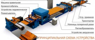
I. General information about the cross-slitting line
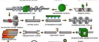
The cross-slitting line can perform roll unwinding, straightening, measuring, slitting and cross-cutting into cut lengths and bagging.
Includes decoiler, straightening device, meter, scissors, conveyor, stacker, hydraulic system, pneumatic system and electrical system, etc., the line can carry out feeding and cutting accuracy testing. Can cut galvanized strip of cold or hot rolled carbon steel, tin plate, stainless steel and other types of strip with protective coating.
The slitting line is controlled by PLC system. Information about length, number of cuts and speed can be entered into the PLC system. When the required number of cuts has been reached, the line can automatically stop. The line speed can be adjusted. There is a high-precision meter/sensor, and the whole line can operate automatically and easily accessible control, with high quality.
II. Specifications
While loading:
Cold-pressed and hot-rolled steel with protective coating Outer diameter of the roll: 1300 mm (max.) Inner diameter of the roll: 600-610mm Strip width: 1250mm (max.) Thickness: 0.3mm -1.2mm (max.) Roll weight: 8ton (max)
When unloading:
Max. cutting length: max. 6000 mm. Number of simultaneously produced longitudinal cuts 10
Line data:
Line speed: max. 30m/min (max.) Length tolerance: ±1.0mm/m Width tolerance: ±0.5mm/m Flatness tolerance: ±1.2mm/m2 Input voltage source: AC. current 380V, 3 phases, 50Hz Control voltage source: AC. current 220V, 50 Hz Solenoid valve: AC. current 220V, 50 Hz Installation position: left to right Electric. control table: 1 for cabinet, 2 for control. tables Capacity up to 50 t/shift
III. Equipment:
1. Coil cart 2. Unwinder 3. Feeding unit 4. Straightening machine 5. Measuring system 6. Slitting unit 7. Edge reeler 8. Cross cutting unit 9. Roller table 10. Sheet stacker and trolley car 11. Hydraulic system 12. Pneumatic system 13. Electrical system with PLC
IV. Description of equipment
1. Roll trolley
Application:
Trolley for feeding rolls with hydraulic drive. Used for moving and loading rolls onto the unwinder.
To save time during operation, a new roll is loaded into the trolley and lifted onto the drum using hydraulics and the trolley begins to move horizontally, putting the roll on the unwinder drum. The loading trolley then moves to its original position.
Design:
The roll feeding trolley is made of high quality materials; installed on reinforced wheels and shafts with roller bearings. The trolley is moved by an electric motor with a gear drive. Signal cable for control of lifting and travel hydraulics.
Technical data:
- Forklift type: with guide bar.
- Load capacity: 8 tons (max)
- Raising/lowering functions: 4 hydraulic cylinders
2. Unwinder
Application:
The decoiler feeds the slitting line and also helps partially rewind the rolls so they can be re-tied while still on the drum before being sent to storage for further use.
Design:
The roll is fed, the end of the strip is clamped and released using a hydraulic clamp. Welded structure made of heat-treated steel, mounted on reinforced shafts with anti-friction bearings. The drum is equipped with a 4-segment movable wedge with hydraulic control for spreading.
The air-controlled braking system ensures maximum reduction of strip sag. An emergency brake is provided to stop the line for any reason.
The function of the unwinder is as follows: capturing a new roll of metal and feeding the strip into the straightening machine in a given mode. Equipped with brake and electric. engine. Once the strip is placed on the correct car, the braking system creates tension on the strip. The operator sets the braking tension of the strip and adjusts it, the strip goes directly into the straightening machine.
Technical data:
- Operating mode: hydraulic
- Load capacity: 8 tons
- Inner diameter: Ø600-610mm
- Tension: air brake
- Roll outer diameter: 1200mm
3. Feed unit
Application:
The roller presses the strip and guides it to the correct machine.
The roller works synchronously with the unwinder and threading device to advance the end of the strip.
The motor drives the pinch roller and presses it against the roll to prevent the end of the strip from springing back when the dressing tapes are removed. The pressure roller allows for re-tying of cut strips when they are rewound on the unwinder. The pressure roller can move either in the feed direction or in the opposite direction.
Design:
The pressure roller is made of high quality steel with supports treated accordingly. thus for installation on anti-friction bearings. The roller is covered with a rubber coating. The roller is driven by an electric motor. The roller and its drive system are mounted on a welded structure, which in turn is mounted on the adjacent decoiler body.
4. The right car
Application
The straightening machine straightens the strip and places it on the cutting line.
Design:
The guide rollers are made of high quality steel. The top rollers bend the strip from the decoiler to match the cutting line and are adjusted up and down by cylinders. The lower roller is driven by a motor.
The main frame is made of high quality thick steel sheets and stress relieved materials. The straightening machine is equipped with hardened gears (55-60HRC/Rockwell), grease-lubricated roller bearings.
The lower frame holds the working rollers, which are supported by rows of short support rollers. The upper bed of the machine holds the working rollers, which are supported by rows of short support rollers. The rows of support rollers are attached to the upper frame and are adjusted by wedge spacers. The upper bridge and therefore the upper row of rollers moves in parallel up and down to adjust the protrusion of the rollers accordingly. with strip thickness using an electric motor or manually. The upper frame rotates horizontally along the axis to ensure more correct adjustment of the input rollers. The position of the bed, and therefore the protrusion of the rollers and the position of the support rollers, are adjusted by a push button. The supporting structure of the machine is designed taking into account possible deformations and has a system for regulating the movements of the upper frame. The straightening machine is powered by a variable speed AC motor with variable speed drives.
Technical data:
- Leveling machine type: driven by rollers.
- Working rollers: – 13 pcs.
- Roller size – Ø65 mm x 1300 mm Length
- Material – 42CrMO
- Hardness – 52 to 60 HRC / Rockwell scale
- Coating – Chrome plating
- Bearing - Roller Bearing
- Working roller drive: 37 kW AC motor
5.Measuring system
Application:
The cutting length measurement is set and controlled by a PLC program logic controller.
Design:
The measuring roller is hard chrome plated. The programmable roller block gives an idea of the cutting length controlled by the sensor. The roller is raised and lowered by a pneumatic cylinder.
6. Slitting unit
Application:
The slitting unit must ensure cutting of the rolled tape into strips of a given width, and, if necessary, trimming the edges on both sides.
The unit for slitting sheet metal has two shafts with stacked knives and inserts that are attached to the shaft, and these knives can be replaced with new ones if necessary. Each knife is equipped with spacer rings for precise adjustment. Inserts with spacers for adjustment. The inserts have the following widths: 5mm, 10mm, 15mm, 20mm, 28mm, 30mm, etc.
Design:
Shaft material: 42CrMo steel, heat treated, ground and chrome plated with required locking. Specially designed for harsh working conditions.
7. Edge reeler
The edge rewinder provides winding of the cut edge of the tape going to waste. The edge winder drive is driven by a gear motor.
8. Cross cutting unit
Application:
Guillotine-type shears must ensure cutting of sheet metal into piece sheets of a given length. The scissors are driven by a gear motor. The length is automatically cut according to the specified parameters via PLC.
Design
Scissor bed
The frame is completely welded from steel plates and tempered to relieve residual stress; two hydraulic cylinders are fixed between the body. The rigid steel frame of the scissors is optimally designed. The frame table is welded to a steel plate support. The shafts are installed in the frame on antifriction bearings.
Set knives
The upper knives are supported by eccentric set screws and a rotary shaft driven by a hydraulic cylinder and a reverse cylinder. Roller guide: The upper knife is guided by a four-point roller guide. For maximum wear resistance, a replaceable hardened pad is provided. It replaces the guide lubricant.
Hydraulic cylinders
The cylinders are precision honed and feature a hard chrome plated piston rod with high quality sealing elements.
Pressing device
Equipped with support plates and articulated with hydraulic cylinders. The action of the cylinder holds the steel strip down for cutting. It can return to its original position by rebounding. The pressing force increases depending on the thickness of the strip. Hydraulic press shoes hold the sheet securely to avoid slipping and kinking, resulting in a clean, straight cut.
Technical data:
- Type: Climb cutting
- Gap adjustment: upper knife
- Knife hardness: 52 to 60HRC/Rockwell
9. Roller table
Design:
The conveyor consists of a loading roller and a tail section with a belt tension roller. The conveyor belt is made of polyester or high-grade rubber. The loading roller is driven by a variable speed AC drive. The conveyor body is manufactured and assembled in such a way as to eliminate vibration. A push/pull roller is mounted at the end of the conveyor table. The top roller should bend the card away from the conveyor to meet the cutting line and lower it onto the platform. The lower roller is equipped with an electric drive.
Technical data:
- Drive motor: AC motor variable frequency
- Tape: endless, polyester or special rubber
10. Sheet stacker and trolley trolley
Application:
Fold cards and piece sheets and unload.
The folding platform is a welded structure with a rotating holder. The rotary holder is activated by a pneumatic cylinder. The paver is equipped with adjustable end and side stops. The holder is moved back and forth by pneumatic cylinders.
Trolley trolley
Application:
Transportation to the warehouse. The cart is designed to run on rails on reinforced wheels. The trolley wheel is hardened to 50 HRC / Rockwell scale. Lateral movement of the trolley: electric motor.
11. Hydraulic system
One hydraulic unit with a backup pump is designed to pressurize the line.
The hydraulic unit consists of:
- backup pumping unit
- standard accessories.
Control valves:
- Control valves for each equipment or unit are installed on the associated equipment and piping.
- Each control valve/valve group is equipped with a stop valve on line P and a check valve on line T for ease of maintenance.
- a pressure switch is provided for the expansion cylinder of the unwinder for locking
12. Pneumatic system
Pneumatic control is used to drive various equipment. A pneumatic distributor is installed on each unit and pipeline.
The pneumatic system consists of:
- piping on the equipment with the necessary flexible pipes with push-in fittings for easy maintenance.
The pneumatic equipment of the line must be powered from a compressed air network with a pressure of 0.4...0.6 MPa.
13. Electrical system with PLC
Photo of decoiler, slitting shears, sheet stacker
Another technical proposal for a longitudinal-transverse cutting line
| Tackle characteristics: | 1x12000 kg or 2.00x1250 mm steel 400 N/mm² or 1.25x1250 mm Inox 600 N/mm² |
| Roll weight: | Max. 12000 kg maximum weight only starting from 1000 mm wide rolls |
| Thickness: Strength: Plate width: Cutting length: | min. 0.40mm max. 2.00mm max. 1.25mm min. 250 N/mm² max. 400N/mm² max. 600 N/mm² min. 250 mm max. 1250 mm min. 250 mm max. 3000 mm |
| Speed: | advancement 1-stage, with frequency converter up to max. 25 m/min. |
| Tolerances: | ±0.50/2000 mm length under the same conditions |
| Reliability/quality: | The machine complies with standards 2006/42/EG – incl. CE designation |
Design features of the equipment
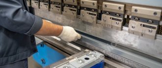
Installations for longitudinal-transverse cutting can be equipped with additional systems and functions. One of the main ones is automatic height control, which has 3 modes - one for burning and two for cutting. This function allows you to increase the service life of consumables and improve cutting quality.
The height at which the metal workpiece is pierced is considered one of the most important parameters for increasing the life of the nozzle and the quality of the cut. During operation, the system moves the plasma cutter down until it contacts the surface of the material, and then sets it at the desired height. After burning the metal with plasma, the controller moves the plasma torch closer to the processed metal.
Photo 7. Operation of an automatic longitudinal-transverse cutting line
With a small distance between the plasma cutter and the metal, the thermal load on consumables increases and the risk of collision with the part increases. Excessively high height has a negative impact on the quality of cutting - the width of the cut and the heat-affected zone increase, which leads to deformation of the workpiece. Therefore, it is important to choose the optimal value, and this task is best handled by an automatic height control system.
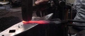
How the lines work
Slitting lines operate on the same principle as any other plasma machine. The technology consists of the formation of a directional plasma arc as a result of the flow of current from the cathode to the anode. The high-speed jet instantly heats the steel workpiece to its melting temperature and blows it out of the cutting zone.
The gantry system is driven by a controller, which is responsible for moving the technological equipment. To do this, the control program developed by the technologist is pre-loaded into the numerical control system. At the same time, the CNC can reproduce contours of any complexity.
Photo 8. The process of cutting blanks of complex configurations
Control programs are developed for cutting both single parts and batch sets of blanks of different shapes and sizes. Using special software on a computer, they are laid out on a sheet of metal of certain dimensions. This makes it possible to rationally use sheet metal and minimize the amount of waste.
Principles and advantages of longitudinal-transverse cutting of metal
The technology for cutting metal rolls consists of preliminary cutting the material into strips of the required length and then exposing the workpieces to electric current.
The metal is separated by melting by point heating of certain sections of the strips with current. The required power and current are determined based on the thickness of the workpiece and its physical and chemical properties, as well as the frequency of the supplied current.
We recommend articles on metalworking
- Steel grades: classification and interpretation
- Aluminum grades and areas of their application
- Defects in metal products: causes and search methods
The metal strip in the cutting area should be locally heated in order to reduce resistance during longitudinal cutting. The achieved effect is possible due to a decrease in the mechanical properties of the metal with increasing temperature. The longitudinal cutting line allows you to make the cut as smooth as possible, with smooth curves, while creating strips of smaller width.
Products produced by longitudinal-transverse cutting meet the standards for the production of bent profiles of welded pipes with straight seams. The technology of longitudinal cutting of rolled metal is also economically beneficial, since it eliminates the need for subsequent processing of manufactured metal strips.
Cross cutting of metal is similar to longitudinal cutting. Special disc shears are used to grip the sheet workpiece. They fix the metal sheet between the shafts, which is then cut. The sheet being cut is pressed by tension against the upper shaft. The upper and lower shafts are constantly moving during the cross cutting process, ensuring continuous feeding of sheets.
VT-metall offers services:
Metal loses its rigidity when exposed to high temperatures, so for cutting it is often preheated with an electric current, and instead of cutting discs, steel rollers with a high carbon content are used. This modification allows you to significantly improve the quality of cutting the material.
Pros and cons of installations
Increasing productivity without losing the quality of products, minimizing production costs are the goals that any enterprise pursues. Modern lines for longitudinal and transverse cutting of metal with a plasma arc are guaranteed to cope with these tasks.
Photo 9. The process of cutting a profile pipe
The equipment has a number of advantages:
- High cutting speed - depending on the model, thickness and grade of steel being cut, it can reach up to 7 m/minute.
- Increased accuracy - a technically sound machine cuts workpieces with a maximum error of up to 0.35 mm.
- Technological flexibility – the ability to cut blanks of any shape and size.
- The minimum level of deformation of cut parts, even when working with thin sheet steel, is ensured due to the directional effect of the plasma arc and a small heat-affected zone.
- High quality of cut - the edges are smooth, without slag, sagging and scale, which eliminates the need for additional processing before welding.
LICO Metal Cutting Line
Cross cutting line LICO JOUANEL (France)
An automated cross-cutting line for rolled metal is an optimal and high-tech solution for cutting metal into sheets. The technology of cutting metal into sheets places special demands on equipment. The lines are an effective solution for those who want to obtain high-quality products using modern equipment using high-precision leveling and feeding equipment.
The lines are produced with a wide range of thickness characteristics - from 0.4 to 2.0 mm. with the width of the initial workpiece from 600 to 1500 mm. The metal cross-cutting line has a quick self-sufficiency and brings a stable profit throughout its entire service life. Our cross cutting lines comply with all European standards and guarantee high quality products.
Our equipment works with various metals - cold-rolled steel, galvanized steel, paint- and polymer-coated metals, aluminum, etc. The thickness of the processed material reaches 2.0 mm. At the same time, the cutting speed, depending on the line configuration, can reach 30 m/min. Lifting mechanisms, like unwinding mechanisms, operate in the range from 5 to 15 tons.
The lines are controlled by modern digital control systems, which ensure high precision cutting and sheet straightening.
Composition of cross cutting line:
A)
Cantilever decoiler DPF1250/M/EI
- Width: 1250 mm
- Max. Roll Ø 1500 mm
- Load capacity 10 tons
- Hydraulic paw release internal diameter 470-540 mm
- Roll clamp with hydraulic drive
- Loading trolley CD5
- Load capacity: 10 tons
- Drive: hydraulic
- Control via remote keypad
B)
Movable telescopic ramp with hydraulic drive.
To facilitate feeding the sheet from the roll to the feed table
For smooth and stable feeding of material into the machine, the receiving table with rollers and two drive shafts (1 steel and 1 rubberized), is equipped with 4 movable guides with mechanical encoders. The guides move with the help of flywheels. Each flywheel has a mechanical encoder showing the exact width between them.
Straightening device with 8 shafts (LICO DEC-3)
- 4 drive shafts
- 4 upper shafts with manual height adjustment with mechanical counter
IN)
Cross cutting module. Includes electromechanical guillotine. Hardened knives made of tool steel with 4 cutting edges allow you to cut metal up to 2.0 mm thick and up to 1500 mm wide without burrs, burrs or waviness.
Control Panel
— 6″ touch screen — Power supply indicator light — Emergency stop button — Work selection selector — Forward/backward (manual mode) — Manual cutting
ACS
- Storage of 3,600 programs in memory
- Automatic speed adjustment for better cutting accuracy (+/- 0.5 mm on two meters of length)
- Unwinder speed 15 m/min
- Automatic calculation of the required material for the program
- Metal loss control when slitting Automatically stops slitting before cross cutting and also to clean blades (a message appears telling the operator to lift the blades and press the start button again to end the cycle, there is an "automatic knife lift option" when equipped with a slitting module)
- Supply voltage 400V, 3 phases
WITH)
Reception table
- Maximum working length 3 m
- Maximum stacking height 150 mm (vertical discrepancy at 150 mm: +/- 1mm)
- 1 central manual limiter, adjustable depending on the program
- 1 leveling system is installed under the cutting line
- Removing the pallet after stacking it on its side using a forklift.
The LICO modular line is a whole complex for sheet metal processing, which allows not only to prepare blanks for subsequent processing, but also to obtain finished products. It may include the following options:
- protective film application module;
- module for longitudinal cutting of metal;
- module for winding cut edges;
- strip cutting module;
- hole punching module;
- transverse or longitudinal Z-profile module;
Manufacturer: Jouanel Industrie Country of origin: France Delivery time: on request
Types of machines
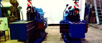
Automatic lines for plasma cutting are divided into several types:
- Stationary – have large dimensions, which eliminates the possibility of moving them without dismantling and using special equipment.
Photo 10. Stationary installation
- Portable – they are small in size, so if necessary they can be moved to another production area or facility.
Photo 11. Portable longitudinal plasma cutting machine
The devices are of two types, depending on the location of the guides for the longitudinal movement of the processing complex:
- directly on a cutting or coordinate table;
Photo 12. Installation with guide rails combined with the work table
- regardless of the table and other structural components of the equipment.
Photo 13. Line with free-standing rail guides
The lines are also produced with different sizes of the coordinate table - the standard width of the working area can be from 1.5 (mainly portable machines) to 8 m (stationary machines).
Line for longitudinal-transverse cutting of rolled metal “K-4PPr-1500”
Application area:
The automated line allows you to cut rolled metal 1500 mm wide into strips of smaller width and a given length, as well as sheets of a given length from thin-sheet coiled steel with or without zinc, polymer coating.
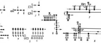
Line composition:
1. Unwinder "RG-10-1500" driven, "cantilever" capacity 10 t with loading cart "TG-10" 2. Slitting machine "K-4PPR" 3. Rewinder "SRG-10-1500" driven, “cantilever” for the finished belt with a belt tensioning device with 10 pcs separators, with an unloading hydraulic cart. Move. carts 3.5 m
Technical characteristics of the line:
Roll width - up to 1500 mm Working area width - 1500+10 mm Metal thickness from 0.40 to 3.0 mm Minimum tape width: - for metal from 1.0 mm to 3.0 mm - 115 mm - for metal from 0 .4 mm to 1.0 mm - 80 mm Internal diameter of the initial roll - 500 - 610 mm Internal diameter of the resulting rolls - 500 - 600 mm Cutting speed in slitting mode up to 30 m/min (set depending on the thickness of the metal) Installed power lines - 54 kW Material of circular knives and guillotine knives - HVG, X 12MF Overall dimensions (LxBxH) - 16000x2500x1700 mm Weight - 18000 kg
Recommended dimensions of the compensation pit:
Length - 3.0 m Width - 1.6 m Depth - 4.0 m
- unwinder
- cart
- Cutting machine
- ACS
- winder
- photo
Automatic roll unwinder - “RG-10-1500” 10 t capacity (driven, cantilever) with a hydraulic drive for opening the legs and a tape clamping device with a drive roller
Type - Cantilever with attached safety support Weight - 2430 kg Load capacity - 10,000 kg Unwinder blades unwinding mode - "wedge" principle Unwinder blades unwinding drive - hydraulic "Duplomatic" Unwinding stroke restrictions - 500-610 mm Unwinder drive 4МЦ2С - asynchronous, frequency-frequency adjustable by Vesper inverter Drive power of the unwinder - 7.5 kW with electric brake Speed of unwinding metal - up to 40 m/min Width of the unwinding roll (blank) - up to 1520 mm Inner diameter of the roll - 500-600 mm Outer diameter of the unwinding roll - 1450 mm Mode operation - automatic Loop monitoring - external rod Emergency sensor for disconnecting the line when the loop is tensioned - limit switch Overall dimensions (LxBxH) - 2300x1160x1300 mm Possibility of reverse rotation (in the opposite direction) - provided Number of unwinder trunk blades - 4 pcs
Loading cart "TG-10"
Load capacity - 10 t Lifting drive - hydraulic Electric drive for moving on rails. Drive power - 1.5 kW Rail track length - 3.5 linear meters.
Longitudinal-transverse cutting machine "K-4PPR"
Composition of the machine: — Guiding filling table; — A pair of pulling shafts (the upper shaft is rubberized with polyurethane); — 11-roll leveling device with reinforced traverses (upper, lower) and 4 pairs of support “shoes” Longitudinal flatness of the sheet by 1 lm. according to GOST 19904-90, “Particularly high”. Drive - asynchronous, frequency-controlled - 15 kW; — A block of longitudinal disc knives with a transfer drive gearbox and an opening outlet support (for installing or removing longitudinal knives); — Drive — asynchronous, frequency-controlled — 11 kW; Standard equipment: 6 pairs of knives with polyurethane rings for metal from 1.0 mm to 3.0 mm (δt≤ 400N/mm2) - Cutting electromechanical guillotine. Processable metal thickness up to 3.0 mm (δt≤ 400N/mm2) — Drive — asynchronous, power — 11 kW — Automated control system (ACS), made on the basis of a processor with a multifunctional control panel.
ACS (automated control system)
Operating modes: Manual - operation of drives by pressing buttons Semi-automatic - operation of guillotine drive by pressing a button, the rest in automatic mode
Automatic - operation of drives according to the controller program Material change mode - stopping the line and a piece of metal for a waste-free change of material Emergency mode - stopping the line without resetting the program in case of failure or malfunction of the unwinder, stacker or guillotine
Total counter of all recycled metal Number of programmable positions (length-quantity) - 16 pcs Control panel - Touch 10″, multifunctional "DeltaElectronics" Controller and frequency drives - "DeltaElectronics" Remote control panels Emergency cable-Stop, with Stop button - included Push-button post for refueling operating modes on the guide table - 1 piece
Automatic roll winder - “SRG-10M-1500” (drive-based, console) with unloading cart “TG-10”, tape tension device with dividers
Type-console, wedge with hydraulic flaps Weight-2700 kg. Car capacity-10,000 kg mode of lifting lobes of unwinder-wedge drive of the lobes of the unwinder-hydraulic restrictions on the passage of the extinction-500-600 mm drive of the aircraft of the rolons 4MC2S-asynchronous, frequency-regulated by the inverter of the “weightper » with brake Coiler drive power - 18 kW with electric brake Metal coiling speed - up to 30 m/min Roll (blank) width - 1500 mm Outer diameter of the coiled roll - 1350 mm Operating mode - automatic Loop monitoring - remote rod Emergency line disconnection sensor when loop tension - limit switch Overall dimensions (LxBxH) - 2300x1300x1800 mm Possibility of reverse rotation - provided Number of winder trunk blades - 4 Roll pressure bar - included Unloading cart "TG-10" - included Mechanical clamping of the ends of the tapes before winding - included
Cost of the equipment set:
Line for longitudinal-transverse cutting of rolled metal “K-4PPR” - on request
Main characteristics
The operating parameters and functionality of the installations are determined by the rated power of the power source used and the presence of additional automation systems. The quality and accuracy of the cut depends on the numerical control system and the skill of the technologist who develops technological cutting maps for the control program. When working, you need to carefully consider the location of the workpieces on the sheet relative to each other, set the necessary allowances, where not only the width of the cut should be taken into account, but also arc fluctuations and other factors.
Photo 14. Cutting process with several plasma cutters
The main characteristics of automatic plasma cutting lines include:
- maximum cutting thickness;
- cutting speed;
- type of drive;
- geometric accuracy of cut workpieces;
- length of guides and distance between them;
- equipment width;
- vertical stroke of the cutter.
The main operating parameters of the cutting process itself are the current, which determines the thickness of the rolled metal being cut, the burning time, the cutting speed and the width of the cut.
It is possible to ensure a perfectly even cut without deformations, sagging and scale only if the current strength and the speed of longitudinal and transverse movement of the plasma torch during cutting are correctly adjusted. The nozzle must also match the operating characteristics of the process, since it is available with different exit cross-sections. Also, by replacing the nozzles, you can significantly expand the range of work performed for a single installation.
Where are they used?
The scope of application of longitudinal-transverse cutting lines is quite wide, since plasma machines are designed for cutting carbon (up to 100 mm thick), alloy steels (up to 50 mm), cast iron (up to 90 mm) and non-ferrous alloys based on copper (up to 80 mm) and aluminum (up to 120 mm).
Photo 15. Operation of lines in a factory environment
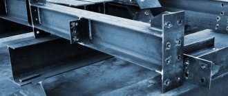
Plasma cutting technology is used in the production of building metal structures, various elements of industrial and metallurgical equipment, parts of ships and aircraft, agricultural machinery, etc.
Automatic plasma cutting is actively used in many industries - the lion's share is occupied by heavy engineering, the construction industry, and metallurgy. The lines are also used in automobile, aircraft, shipbuilding, bridge construction and other fields of activity.