Calculators for calculating cone development sizes
Sometimes, while performing certain chores, the master is faced with the problem of making a cone - full or truncated.
This could involve operations on, say, thin sheet metal, flexible plastic, regular fabric, or even paper or cardboard. And the tasks are very different - making casings, adapters from one diameter to another, canopies or deflectors for a chimney or ventilation, funnels for gutters, a homemade lampshade. Or maybe even just a fancy dress for a child or crafts assigned by the labor teacher at home. Calculators for calculating cone development sizes
To roll a three-dimensional figure with given parameters from a flat material, you need to draw a development. And for this you need to calculate mathematically and transfer graphically the necessary exact dimensions of this flat figure. We will look at how this is done in this publication. Calculators for calculating the dimensions of the cone sweep will help us in this matter.
DIY chimney cap
House owners often resort to using elements in the form of various caps and umbrellas, which, as it seems at first glance, serve to decorate chimneys. At the same time, such attachments not only improve the aesthetic perception of the structure, but also provide useful functionality. Usually the so-called chimney canopy is made in-house, since this does not require serious knowledge and skills. Although, along with the simple design of these elements, there are quite intricate crafts that are problematic to build without the appropriate experience.
Design features
A chimney cap is a device designed to protect the pipe from moisture. The appearance of such canopies can be different, which depends both on the preferences of the owner of the house and on the configuration of the pipe.
Chimney caps include:
- umbrella - protection from precipitation, foreign objects and bird penetration installed on the top of the hood, the appearance of which has the shape of a pyramid, cone or corresponds to other geometry;
- apron - part of the cap responsible for protecting the top of the pipe from water flowing from the umbrella. Typically, the installation of this element is carried out when equipping a rectangular or square pipe. As a result, an increase in the service life of the chimney is guaranteed, since it is possible to practically eliminate the likelihood of corrosion and fungus;
- brackets – fastening elements, which are metal strips that allow you to connect the visor and the apron. Direct fastening in this case is carried out through the use of welding.
Keep in mind! It is quite possible to assemble a chimney cap yourself, but only if you want to install a fairly simple weather vane. Models that are more complex in terms of design features are much more profitable to order or buy.
If you have a choice, it is best to give preference to those models that are equipped with an opening lid. This will allow for preventive inspection of the chimney and its cleaning without any problems, which is associated with ease of access.
A long-lasting chimney cap can only be made of corrosion-resistant iron: galvanized steel, aluminum and copper. In the latter case, the proposed metal has a pronounced decorative character, since its shimmer in the sun can give your home a certain respectability.
Place a cap on the chimney pipe to extinguish sparks. This is one of its purposes. Therefore, the quality of the iron must be good, so it will not burn out for a long time.
Due to the fact that chimneys come in a variety of shapes and sizes, cap manufacturers also offer a wide range of products. If you decide to decorate your home and extend the life of the chimney, you will have to choose from a large assortment of weather vanes:
- Standard - a chimney umbrella in the form of a pyramid, for the manufacture of which sheet metal is used, and fastening to the apron is carried out using brackets.
- Four-slope - installed mainly on rectangular pipes made of brick. The shape corresponds to a hip roof with four slopes.
- With a semicircular umbrella - it is visually beautiful, but provides insufficient traction. Mainly used for installation on chimneys of houses built according to European standards.
- Flat - can often be found on Art Nouveau buildings. It has a rectangular shape and has the disadvantage of increased load on the brackets, which in some cases leads to their deformation. This is due to the flat roof of the hood, which prevents snow from rolling off. This fact determines the occurrence of the mentioned problem.
- Round with a cone-shaped umbrella - models without a drip, installed on round chimneys made of stainless steel.
How to make a chimney - protection for a pipe?
To prevent precipitation from getting into the chimney and to prevent it from being destroyed by ice, it must be protected with a chimney. Master tinsmiths can make a chimney of the most bizarre shapes; sometimes a weather vane is installed on the chimney, indicating the direction of the wind. But you can make a chimney of a simple design on a chimney pipe made of metal or brick with your own hands.
Installation of chimneys
Since ancient times, chimneys have protected the chimneys of houses; they have not lost their relevance today. If wood-burning stoves are rare in homes today, then almost every country house has a fireplace, the exhaust pipe of which must be protected from precipitation, birds, autumn leaves and other foreign objects.
All other pipes that go to the roof need the same protection: ventilation and chimney pipes of gas heating devices. In addition to their protective and decorative function, chimneys can perform another function: they improve the circulation of hot air in fireplaces and stoves. Let's figure out how to make a chimney with your own hands.
Types of chimneys
Chimneys may differ from each other in roof shape, material of manufacture, and the presence of additional structural elements. Therefore, before you start doing the work yourself, it’s worth getting acquainted with their varieties.
Chimney roof shapes
It is enough to look carefully at the roofs of houses in some village or suburban settlement to be convinced that human imagination is inexhaustible in various inventions. Chimneys are decorated with chimneys of various shapes, and some craftsmen use instead of them holey cast iron pots, teapots, buckets and even milk flasks.
If you want to make a real beautiful chimney with your own hands, you will be interested to know what shape you can give it. The following forms of chimney roofs are distinguished:
- Tent.
- Vaulted (semi-cylindrical).
- Gable.
- Four-slope (hip).
- Four-pincer.
- Spire-shaped.
- Flat, etc.
In the photos below you can see some of the options listed.
Smokehouse with hip roof
Smokehouse with four-gable roof
The materials for making chimneys are most often galvanized or stainless steel and copper sheets. They can have a polymer coating of various shades to protect against corrosion.
Calculators for calculating cone development sizes
A few words about the calculated parameters
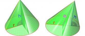
It will not be difficult to understand the calculation principle by understanding the following diagram:
A truncated cone with defining dimensions and its development. A truncated cone is shown, but with a full one - the principle does not change, and calculations and construction become even simpler.
So, the cone itself is determined by the radii of the bases (lower and upper circles) R1 and R2 , and the height H. It is clear that if the cone is not truncated, then R2 is simply equal to zero.
The letter L indicates the length of the side (generator) of the cone. In some cases, it is already known - for example, you need to make a cone according to a sample or cut out material to cover an existing frame. But if it is unknown, it doesn’t matter, it’s easy to calculate.
The scan is shown on the right. For a truncated cone, it is limited by the sector of the ring formed by two arcs, external and internal, with radii Rb and Rs . For a full cone, Rs will also be zero. It is clearly seen that Rb = Rs + L
The angular length of the sector is determined by the central angle f , which in any case must be calculated.
All calculations will take literally a minute if you use the offered calculators:
Step 1 - determining the length of the generatrix L
(If it is already known, the step is skipped)
Step 2 - determining the radii of the inner and outer sweep arc
Radii are calculated one by one - with a choice in the corresponding field of the calculator.
Types of rolling
The main types of rolling include the following:
- Pipe rolling (flaring) - used to change the radius of the pipe.
- Sheet metal rolling
is the procedure of bending a sheet of metal into a radius.
Pipe rolling is carried out on pipe bending machines, which are capable of rolling pipes with a diameter of up to 30 cm. Angles, channels and other parts are processed using the same equipment.
Radius rolling is used for stainless, ferrous, galvanized metals of various thicknesses: steel, aluminum, copper. For sheets with a thickness of over 10 mm, heating is required. Metal sheets up to 10 mm thick are cold bent. One of the more complex technological processes of sheet metal rolling
- This is the making of cones. We also have equipment that produces conical and cylindrical shells.
If you need sheet metal rolling in Moscow
— our company is ready to perform custom-made services with high quality, at a high professional level. Our craftsmen have enormous experience and produce parts with the most accurate radius. They thoroughly know the operating principle of the equipment, scrupulously follow the technology, and adhere to all the nuances of metal processing.
Bending technology - basic information
Metal bending is performed without welding seams, which avoids corrosion in the future and produces a product of increased strength. Deformation does not require significant effort and is usually performed in a cold state.
The exception is hard materials such as duralumin or carbon steels. Sheet metal bending technology is developed according to the assigned tasks in such options as:
A special case is flexion with stretching. This technology is used in the manufacture of parts with large bending radii and small diameters. When making parts with your own hands, the process is combined with operations such as cutting or punching.
Soft types of metals and alloys, such as brass, copper, and aluminum, are well suited for home processing. The production of products by bending is carried out on rolling or rolling machines, or manually.
The last procedure is quite labor-intensive. Bending is done using pliers and a rubber hammer. If the sheet is thin, use a mallet.
How to bend at right angles
To bend a bracket from a metal sheet, you will need a set of tools and accessories, consisting of:
- vice,
- hammer,
- power saws,
- bar,
- frames
The length of the strip is made according to the scheme, with the calculation that there should be a margin of 0.5 mm for each bend, plus another millimeter for folds on both sides. The workpiece is placed in a vice with squares. Clamping it along the fold line, process it with a hammer.
After this, the future bracket is unfolded in a vice, clamped with a frame and a block, and the other side is formed. The workpiece is pulled out, the required length of the sides is measured, making bends along the bottom.
Use a triangle to check the correctness of the angle, correcting inaccuracies with a hammer. When performing both operations, the workpiece is pressed with a block and a frame. The finished staple is filed to the desired size.
How to make a sheet bending machine yourself
To give the metal the desired configuration, tinsmiths use a sheet bending machine. But what should a master do if he doesn’t have special equipment at hand?
In fact, the question of how to bend sheet metal at home is easily resolved. It is enough to use your own ingenuity and basic equipment to make a simple machine.
To make a bender for a metal profile, you will need:
- I-beam 80 mm,
- fasteners (bolts),
- loops,
- corner 80 mm,
- clamps,
- a pair of handles.
You will also need a welding machine and a stable table on which the finished machine is mounted.
The basis of the device is an I-beam, to which a corner is screwed with two bolts, holding the workpiece during the bending process. Three door hinges are attached under it by welding. Their second part is welded directly to the corner.
In order for the machine to easily turn while bending sheet metal, handles are attached to it on both sides. The finished machine is secured to the table with clamps. Before laying the workpiece, the corner is unscrewed or lifted. The sheet is pressed, aligned along the edge and folded, turning the machine by the handles. The homemade device is only suitable for processing workpieces of small thickness.
Bending a metal sheet with a hammer
In order to bend a sheet up to 1.2 mm thick at a right angle, use the simplest tools - pliers (clamps) and a rubber hammer.
The processing is carried out on a flat wooden block. The fold line is drawn using a pencil and ruler. Then the sheet is clamped with pliers so that their ends fall exactly on the marking line.
The edge is gradually bent upward, moving along the fold. Once the angle approaches 90 degrees, the sheet is placed on the block and finally leveled using a hammer.
Narrow parts, such as tin edges, are made in this way.
Tip: Use a rubber or wooden hammer to prevent dents from forming on the metal. If bending is performed with a conventional tool, you need to take a textolite plate as a gasket.
It is convenient to bend sheets up to 2 mm thick on a desktop. The metal is positioned so that the marking line falls on the edge. A steel corner is placed under the material being processed.
The sheet is clamped in a vice using two wooden blocks. Bending is done using a hammer, tapping the metal from one end to the other. At the same time, the edge of the sheet is directed downward so that it ultimately lies completely on the corner fixed along the edge of the table. This method can be used to make products of any width, including boxes or barbecues.
Making pipes without using a machine
Home craftsmen have invented a lot of ways to bend a metal sheet into a pipe without using a machine.
We propose to consider the simplest option using a blank of suitable size. It is made from an old pipe of suitable diameter.
A sheet of metal is laid out on the floor and a piece of the required length is cut from it. To determine the required size, the required pipe diameter is multiplied by 3.14 and added 30 mm for the seam.
A pair of tubes are welded to the blank on both sides, perpendicular to one another. The crowbar should be freely inserted into their holes.
Master's recommendation: by bending a metal sheet using a blank, it is convenient to make pipes no more than a meter in length.
To use the device, the effort of three people is required. The blank is placed on the edge of the sheet. One person stands on top, two others screw the metal onto the blank, turning the crowbar 90 degrees.
The entire length of the sheet is rolled in this way, the remaining edge is hammered. The seam is secured by welding.
It must be taken into account that the bend radius of sheet metal depends on its thickness and manufacturing method. Hot rolled steel is more suitable for pipes; profile products are made from cold rolled steel.
Inclined cone development
Let us consider the procedure for constructing a scan of the lateral surface of an inclined cone using the approximation (approximation) method.
- We inscribe the hexagon 123456 into the circle of the base of the cone. We connect points 1, 2, 3, 4, 5 and 6 with the vertex S. The pyramid S123456, constructed in this way, with a certain degree of approximation is a replacement for the conical surface and is used as such in further constructions.
- We determine the natural values of the edges of the pyramid using the method of rotation around the projecting straight line: in the example, the i axis is used, perpendicular to the horizontal projection plane and passing through the vertex S. Thus, as a result of rotation of the edge S5, its new horizontal projection S'5'1 takes a position at which it is parallel to the frontal plane π2. Accordingly, S''5''1 is the natural value of S5.
- We construct a development of the lateral surface of the pyramid S123456, consisting of six triangles: S16, S65, S54, S43, S32, S21. The construction of each triangle is carried out on three sides. For example, △S16 has length S1=S''1'', S6=S''6''1, 16=1'6'.
The degree to which the approximate development corresponds to the actual one depends on the number of faces of the inscribed pyramid. The number of faces is chosen based on the ease of reading the drawing, the requirements for its accuracy, the presence of characteristic points and lines that need to be transferred to the development.
Transferring a line from the surface of a cone to a development
Line n lying on the surface of the cone is formed as a result of its intersection with a certain plane (figure below). Let's consider the algorithm for constructing line n on a scan.
- We find the projections of points A, B and C at which line n intersects the edges of the pyramid S123456 inscribed in the cone.
- We determine the natural size of the segments SA, SB, SC by rotating around the projecting straight line. In the example under consideration, SA=S''A'', SB=S''B''1, SC=S''C''1.
- We find the position of points A, B, C on the corresponding edges of the pyramid, plotting on the scan the segments SA=S''A'', SB=S''B''1, SC=S''C''1.
- We connect points A, B, C with a smooth line.
Bending technology - basic information
Metal bending is performed without welding seams, which avoids corrosion in the future and produces a product of increased strength. Deformation does not require significant effort and is usually performed in a cold state.
The exception is hard materials such as duralumin or carbon steels. Sheet metal bending technology is developed according to the assigned tasks in such options as:
A special case is flexion with stretching. This technology is used in the manufacture of parts with large bending radii and small diameters. When making parts with your own hands, the process is combined with operations such as cutting or punching.
Soft types of metals and alloys, such as brass, copper, and aluminum, are well suited for home processing. The production of products by bending is carried out on rolling or rolling machines, or manually.
The last procedure is quite labor-intensive. Bending is done using pliers and a rubber hammer. If the sheet is thin, use a mallet.
How to bend at right angles
To bend a bracket from a metal sheet, you will need a set of tools and accessories, consisting of:
- vice,
- hammer,
- power saws,
- bar,
- frames
The length of the strip is made according to the scheme, with the calculation that there should be a margin of 0.5 mm for each bend, plus another millimeter for folds on both sides. The workpiece is placed in a vice with squares. Clamping it along the fold line, process it with a hammer.
After this, the future bracket is unfolded in a vice, clamped with a frame and a block, and the other side is formed. The workpiece is pulled out, the required length of the sides is measured, making bends along the bottom.
Use a triangle to check the correctness of the angle, correcting inaccuracies with a hammer. When performing both operations, the workpiece is pressed with a block and a frame. The finished staple is filed to the desired size.
How to make a sheet bending machine yourself
To give the metal the desired configuration, tinsmiths use a sheet bending machine. But what should a master do if he doesn’t have special equipment at hand?
In fact, the question of how to bend sheet metal at home is easily resolved. It is enough to use your own ingenuity and basic equipment to make a simple machine.
To make a bender for a metal profile, you will need:
- I-beam 80 mm,
- fasteners (bolts),
- loops,
- corner 80 mm,
- clamps,
- a pair of handles.
You will also need a welding machine and a stable table on which the finished machine is mounted.
The basis of the device is an I-beam, to which a corner is screwed with two bolts, holding the workpiece during the bending process. Three door hinges are attached under it by welding. Their second part is welded directly to the corner.
In order for the machine to easily turn while bending sheet metal, handles are attached to it on both sides. The finished machine is secured to the table with clamps. Before laying the workpiece, the corner is unscrewed or lifted. The sheet is pressed, aligned along the edge and folded, turning the machine by the handles. The homemade device is only suitable for processing workpieces of small thickness.
Bending a metal sheet with a hammer
In order to bend a sheet up to 1.2 mm thick at a right angle, use the simplest tools - pliers (clamps) and a rubber hammer.
The processing is carried out on a flat wooden block. The fold line is drawn using a pencil and ruler. Then the sheet is clamped with pliers so that their ends fall exactly on the marking line.
The edge is gradually bent upward, moving along the fold. Once the angle approaches 90 degrees, the sheet is placed on the block and finally leveled using a hammer.
Narrow parts, such as tin edges, are made in this way.
Tip: Use a rubber or wooden hammer to prevent dents from forming on the metal. If bending is performed with a conventional tool, you need to take a textolite plate as a gasket.
It is convenient to bend sheets up to 2 mm thick on a desktop. The metal is positioned so that the marking line falls on the edge. A steel corner is placed under the material being processed.
The sheet is clamped in a vice using two wooden blocks. Bending is done using a hammer, tapping the metal from one end to the other. At the same time, the edge of the sheet is directed downward so that it ultimately lies completely on the corner fixed along the edge of the table. This method can be used to make products of any width, including boxes or barbecues.
Making pipes without using a machine
Home craftsmen have invented a lot of ways to bend a metal sheet into a pipe without using a machine.
We propose to consider the simplest option using a blank of suitable size. It is made from an old pipe of suitable diameter.
A sheet of metal is laid out on the floor and a piece of the required length is cut from it. To determine the required size, the required pipe diameter is multiplied by 3.14 and added 30 mm for the seam.
A pair of tubes are welded to the blank on both sides, perpendicular to one another. The crowbar should be freely inserted into their holes.
Master's recommendation: by bending a metal sheet using a blank, it is convenient to make pipes no more than a meter in length.
To use the device, the effort of three people is required. The blank is placed on the edge of the sheet. One person stands on top, two others screw the metal onto the blank, turning the crowbar 90 degrees.
The entire length of the sheet is rolled in this way, the remaining edge is hammered. The seam is secured by welding.
It must be taken into account that the bend radius of sheet metal depends on its thickness and manufacturing method. Hot rolled steel is more suitable for pipes; profile products are made from cold rolled steel.
Cone base
To find out the radius of the base of the conical frame, use a ruler to measure the diameter of the lower part of the workpiece, which is a paper (cardboard) side surface.
For greater accuracy, apply a ruler to the edges of the workpiece and measure the distance in two perpendicular directions. Calculate the average diameter and divide in half. As a result, the radius of the base of the paper cone is obtained.
- Using a compass, draw a circle on the prepared second sheet of paper, the radius of which is equal to half the diameter of the base of the cone. At this stage of production, you need to try on the base of the already made side surface to the drawn circle. And, if everything matches, then proceed to the next step.
- Having placed the leg of the compass in the center of the drawn circle, increase the expansion of the compass, making an allowance of 1.5 centimeters, and draw another circle.
- A circle is cut out along the line of the outer circle with scissors and cuts are made along the entire perimeter from the edge of the cut out circle to the line of the inner circle.
- The notches are bent to one side at an angle of 90 degrees. The result is the bottom of a cone with curved edges to connect to the side surface.
- All that remains is to coat the lower inner part of the sidewall with glue to a depth of 1.5 cm and carefully insert the manufactured bottom with notches inside the cone.
Source: https://ooocentrsvarki.ru/stanki/usechennyj-konus-svoimi-rukami.html
Methods for making cones
Cone is a fairly common shape of parts, which is made on screw-cutting lathes. Cones have many modifications. They are made from different materials - steel, bronze, copper. To begin with, a blank in the form of a “herringbone” is made. This will help you produce the part quickly and without waste. There are different methods for processing such workpieces:
- To process cones (inside, outside) that are small in size, turning is used by turning the upper slide of the caliper. The cutting slide is rotated to the required angle.
- For long parts with a small taper angle, use off-center processing of the tailstock. To determine the lateral displacement, a special formula is used.
- Processing using a tapered ruler allows you to obtain accurate dimensions of the part. Their size should not exceed the size of the ruler.
- A wide cutter is used for parts not exceeding 15-20 cm in length. Having a large angle of inclination and not requiring great precision.
When choosing any type of processing, you should pay attention to the complexity of the design, the metal from which the cone is made, and the size of the part. The correctly chosen processing method is a guarantee of producing a high-quality part. Such machines should be operated by professionals. The result will depend on their skills.
Learn how to make a truncated cone or round transition with your own hands
In everyday life, of course, you have to do everything yourself if you have your own yard, house, dacha, construction. Perhaps a little advice in the article with sections on how to make a cone or transition with your own hands will help you around the house, without extra costs.
For example, let's take a bucket made of metal or other material. It has two different diameters. The smallest one is made at the bottom with a closed bottom. The bucket is made in the shape of a truncated cone.
Round transitions are used everywhere, for example ventilation, from one round diameter to another round diameter, also in the form of a truncated cone.
Take a random cone size with a diameter of 250 x 150 mm and a height of 180 mm (you have your own dimensions). Figure A.
We make a pattern of the part on which we will create the transition. The first diameter of 250 mm is multiplied by P = 3.14 and the result is 785 mm. Then we divide 785 mm into 10 parts. We divide the resulting amount of 78.5 mm into 2 parts. See the example in the figure.
Next, we draw a part template, using it we will make a cone pattern. Figure B.
We outline the part template 10 times. You get a development of a truncated cone. Figure B.
Locks or connections are indicated in yellow. How will you connect your right. Locks for tightness, can be used with bolts, self-tapping screws, welding seam, glue, overlap. The only thing we don’t forget to add to the connection. When you have completely traced the template, round off the straight ends slightly.
Next, after assembling the cone, bead the edge of the cone along the edges with a hammer to secure the straight shell. It is better to make the height of the shell more than 60 mm.
It is better to make a sample of the first pattern from paper cardboard, so as not to spoil the material.
Source: https://xn——dlckc9bidcgrpu.xn--p1ai/stroitelstvo/uchimsya-delat-usechennyj-konus-ili-kruglyj-perexod-svoimi-rukami.html
Metal bending on rollers
07 Dec 2013 Category: Mechanics |
Recently, I have received several requests from blog readers for help in solving the same problem: how to determine the final location of the middle roller (roll) when working on three-roll sheet bending rolls and profile benders...
...relative to the position of the outer rollers (rolls), which will ensure bending (rolling) of the workpiece with a certain specified required radius? The answer to this question will increase labor productivity when bending metal by reducing the number of runs of the workpiece until a suitable part is obtained.
In this article you will find theoretical
solving the problem. Let me make a reservation right away: I did not apply this calculation in practice and, accordingly, did not check the effectiveness of the proposed method. However, I am confident that in certain cases metal bending can be done much faster using this technique than usual.
Most often, in normal practice, the final location of the movable central roller (roll) and the number of passes until a suitable part is obtained is determined by the “poke method”. After a long (or not so long) development of the technological process on a test part, the coordinate of the position of the central roller (roll) is determined, which is used for further reconfiguration of the rollers, producing a batch of these parts.
The method is convenient, simple and good for a significant number of identical parts - that is, for mass production. In single or “very small-scale” production, when it is necessary to bend different profiles or sheets of different thicknesses with different radii, the loss of time for adjustment “at random” becomes catastrophically huge. These losses are especially noticeable when bending long (8...11 m) workpieces! While you make the pass..., while you take measurements..., while you rearrange the position of the roller (roller)... - and all over again! And so a dozen times.
Calculation in Excel of the location of the moving middle roller
Launch MS Excel or OOo Calc and get started!
General rules for formatting spreadsheets that are used in blog articles can be found here.
First of all, I would like to note that sheet bending rollers and profile benders of different models may have movable outer rollers (rollers), or they may have a movable middle roller (roller). However, for our task this is not of fundamental importance.
The figure below shows the calculation diagram for the problem.
At the beginning of the process, the part to be rolled lies on two outer rollers (rolls) having a diameter D
.
The middle roller (roller) with diameter d
is brought
until it touches the top of the workpiece
.
Next, the middle roller (roller) moves down to a distance equal to the design size H
, the roller rotation drive is turned on, the workpiece is rolled, the metal is bent, and the output is a part with a given bending radius
R
!
H
correctly, quickly and accurately . This is what we will do.
Initial data:
1. Diameter of the movable upper roller (roller) /for reference/ d
write in mm
to cell D3: 120
2. Diameter of support rollers (rolls) with rotation drive D
we write in mm
to cell D4: 150
3. Distance between the axes of the support outer rollers (rolls) A
in mm enter
to cell D5: 500
4. Height of the section of the part h
enter in mm
to cell D6: 36
5. Internal bending radius of the part according to drawing R
enter in mm
to cell D7: 600
Calculations and actions:
6. Calculate the estimated vertical feed of the upper roller (roll) H calc.
in mm
excluding springing
in cell D9: =D4/2+D6+D7- ((D4/2+D6+D7)2- (D5/2)2)(½) =45.4
H calculated =D/2+h+R— ((D/2+h+R)2- (A/2)2)(½)
7. Adjust the rollers to this size H calc.
and make the first run of the workpiece.
We measure or calculate the resulting internal radius from the chord and height of the segment, which we denote as R
and write the resulting value in mm
to cell D10: 655
8. We calculate what the calculated theoretical vertical feed of the upper roller (roll) should be H 0calc
in mm for the manufacture of a part with a radius
R
without taking into account springing
in cell D11: =D4/2+D6+D10- ((D4/2+D6+D10)2- (D5/2)2)(½)=41,9
H0calc =D/2+h+
R0 - ((D/2+h+ R0 )2- (A/2)2)(½)
9. But a part with an internal bending radius
R was obtained with the upper roll lowered to size Hcalc , and not H 0calc !!!
We calculate the correction for back springing
x
in mm
in cell D12: =D9-D11=3,5
x = H calc -
H 0calc
10. Since the radii R
and
R
have similar dimensions, then the same correction value
x
to determine the final actual distance
H
to which the upper roller (roller) must be moved down to obtain an internal radius
R
.
We calculate the final calculated vertical feed of the upper roller (roll) H
in mm taking into account springing
in cell D13: =D9+D12=48,9
Calculators for calculating cone development sizes
Sometimes, while performing certain chores, the master is faced with the problem of making a cone - full or truncated. This could involve operations on, say, thin sheet metal, flexible plastic, regular fabric, or even paper or cardboard. And the tasks are very different - making casings, adapters from one diameter to another, canopies or deflectors for a chimney or ventilation, funnels for gutters, a homemade lampshade. Or maybe even just a fancy dress for a child or crafts assigned by the labor teacher at home.
Calculators for calculating cone development sizes
To roll a three-dimensional figure with given parameters from a flat material, you need to draw a development. And for this you need to calculate mathematically and transfer graphically the necessary exact dimensions of this flat figure. We will look at how this is done in this publication. Calculators for calculating the dimensions of the cone sweep will help us in this matter.
Calculators for calculating cone development sizes
A few words about the calculated parameters
It will not be difficult to understand the calculation principle by understanding the following diagram:
A truncated cone with defining dimensions and its development. A truncated cone is shown, but with a full one - the principle does not change, and calculations and construction become even simpler.
So, the cone itself is determined by the radii of the bases (lower and upper circles) R1 and R2 , and the height H. It is clear that if the cone is not truncated, then R2 is simply equal to zero.
The letter L indicates the length of the side (generator) of the cone. In some cases, it is already known - for example, you need to make a cone according to a sample or cut out material to cover an existing frame. But if it is unknown, it doesn’t matter, it’s easy to calculate.
The scan is shown on the right. For a truncated cone, it is limited by the sector of the ring formed by two arcs, external and internal, with radii Rb and Rs . For a full cone, Rs will also be zero. It is clearly seen that Rb = Rs + L
The angular length of the sector is determined by the central angle f , which in any case must be calculated.
All calculations will take literally a minute if you use the offered calculators:
Step 1 - determining the length of the generatrix L
(If it is already known, the step is skipped)
Step 2 - determining the radii of the inner and outer sweep arc
Radii are calculated one by one - with a choice in the corresponding field of the calculator.
Source: https://stroyday.ru/kalkulyatory/obshhestroitelnye-voprosy/kalkulyatory-rascheta-razmerov-razvertki-konusa.html