Definition and elements of a cone
A cone is understood as a body consisting of a circle and a point that is removed from its surface at a certain distance.
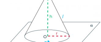
In this case, the point is connected to the base by drawing rays, which are called generators. The line connecting the center of the circle with the distant point is the height of this figure.
Note!
There is also such a thing as the cone axis. This is a line passing through its center and coinciding with the height. Generators are constructed relative to the axis.
I would like to consider a few more concepts on this topic:
1. By taper we mean the ratio of the diameter of the base of a figure and its height:
Important!
Taper is responsible for the angle of inclination of the generatrices. The larger this parameter, the sharper the angle.
2. An axial section assumes the presence of a plane that will dissect the figure, passing through the axis:
3. Tangent is a plane that is in contact with the generatrix of the cone. It is important that it is perpendicular to the axial section.
Round cone in geometry
Let us give a geometric definition of this figure. A circular cone is a surface that is formed by straight segments connecting all points of a certain circle with one single point in space. This single point must not belong to the plane in which the circle lies. If instead of a circle we take a circle, then this method also leads to a cone.
You may be interested in: Law College in Ivanovo: specialties, admissions committee, reviews
The circle is called the base of the figure, its circumference is the directrix. The segments connecting a point to a directrix are called generators or generators, and the point where they intersect is the vertex of the cone.
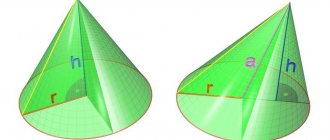
A round cone can be straight or inclined. Both figures are shown below in the figure.
You may be interested in: Thermophilic bacteria: benefits and harm for humans
The difference between them is this: if the perpendicular from the top of the cone falls exactly at the center of the circle, then the cone will be straight. For him, the perpendicular, which is called the height of the figure, is part of its axis. In the case of an inclined cone, the height and axis form some acute angle.
Due to the simplicity and symmetry of the figure, we will further consider the properties of only a straight cone with a round base.
Properties of a circular cone
There are several features that this type of figure has:
- The generators of a circular cone are equal to each other.
- To find the center of gravity of a figure, you need to divide its height into four parts.
- The intersection of the section plane and the base forms a parabola. If you draw a section plane through the top of the body, you get an isosceles triangle.
Interesting fact!
If you rotate a right triangle around one of its legs, you get a cone. It is important that the rotation angle is at least 360 degrees.
Getting a shape using rotation
Before moving on to considering the development of the surface of a cone, it is useful to learn how this spatial figure can be obtained using rotation.
Suppose we have a right triangle with sides a, b, c. The first two of them are legs, c is the hypotenuse. Let's place the triangle on side a and begin to rotate it around side b. The hypotenuse c will describe a conical surface. This simple technique for obtaining a cone is shown in the diagram below.
Obviously, leg a will be the radius of the base of the figure, leg b will be its height, and hypotenuse c corresponds to the generatrix of a round right cone.
Volume of a truncated cone
This is the part of a straight cone that is located in the space between the base and a plane parallel to this base. In general it looks like this:
The volume of a given body can be calculated using the formula:
Important! S and S1 are the areas of the corresponding bases, which are equal to PR2 and PR12. An online calculator will help you find these values.
Online calculator
General definition of a cone
A cone is a body formed by the combination of all rays emanating from a point in space and intersecting a plane.
The point from which the rays emanate is called the apex of the cone. When the base of the cone is a polygon, it turns into a pyramid.
Let's look at some important concepts.
The generatrix of a cone is a segment that connects any point on the boundary of the base of the cone with its vertex. The height of a cone is the perpendicular that extends from the top to the base of the body.
There are several types of cone:
Straight if its base is one of such shapes as an ellipse or a circle. A prerequisite is the projection of the top of the cone to the center of the base.
Oblique - its center of the figure, which is located at the base, does not coincide with the projection of the vertex onto this very base.
Circular - based on the name, it is clear that at its base lies a circle.
Truncated - an area of a cone lying between the base and a section of the plane that is parallel to the base and intersects this cone.
Area of a truncated cone
To find this parameter you need to use the formulas:
- lateral surface area of the truncated cone Sside;
- the total area of the truncated figure Spol, which is equal to the sum of the areas of the two bases and the area of the lateral surface:
Here l is the length of the generatrix, and R and r are the radii of the larger and smaller bases, respectively.
Constructing a cone scan on paper
To complete this task you will need a piece of paper, a pencil, a protractor, a ruler and a compass.
First of all, let's draw a right triangle with sides 3 cm, 4 cm and 5 cm. Its rotation around a leg of 3 cm will give the desired cone. The figure has r = 3 cm, h = 4 cm, g = 5 cm.
Let's begin constructing the development by drawing a circle of radius r with a compass. Its length will be equal to 6*pi cm. Now next to it we will draw another circle, but with radius g. Its length will correspond to 10*pi cm. Now we need to cut off a circular sector from the large circle. Its angle φ is equal to:
φ = 2*pi*r/g = 2*pi*3/5 = 216o.
Now, using a protractor, we plot this angle on a circle with radius g and draw two radii that will limit the circular sector.
Thus, we have constructed a development of a cone with the specified parameters of radius, height and generatrix.
Enter the base radius and height of the cone
| Cone radius r | |
| Cone height h | |
| Result | |
| Calculation of the volume of a cube, pyramid, cone, cylinder, ball (volume of all figures). | |
| Volumes of figures | |
| Radius: | |
| Height: | |
| A cone is a geometric body that consists of a circle (the base of the cone), a point not lying in the plane of this circle (the top of the cone), and all the points connecting the top of the cone with the points of the base. Formula for the volume of a cone: , where R is the radius of the base, h is the height of the cone | |
How to calculate the angle of a cone
| Cone elements | Calculation formulas | Cone elements | Calculation formulas |
| K | K = (Dd)/ l K = 2tga | D | D = K× l + d D = 2× l×tga + d |
| a | tga = (Dd)/ 2l tga = K / 2 | d | d = D – 2× l×tga d = D – K× l |
Angle a is calculated using the trigonometric tangent function.
Normal conical surfaces must be made to standard dimensions, some of which are listed in Table 4.
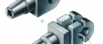
In addition to these surfaces, there are also Morse cones and metric cones. External Morse cones are made on the tail part of the drills (see Fig
), countersinks, reamers, centers, and internal cones - in the holes of spindles, mandrels, adapter bushings into which these tools are installed.
There are seven numbers of Morse cones (from to 6
) with their own sizes and angles of inclination
a
.
The smallest is the Morse cone ( 1:19.212
), the largest is the Morse cone
6
(
1:19.18
).
Their dimensions are given in the ST SEV 147-75 standard. The disadvantage of Morse cones is the different angles of inclination a
for different numbers.
Table 4
Standard sizes of part cones
| Taper K | Cone angle 2a | Tilt angle a | Taper designation |
| 1:100 1:50 1:20 1:10 1:3 1:1,866 1:1,207 1:0,866 | 0 0 34¢23² 1 0 8¢45² 2 0 51¢51² 5 0 43¢29² 18 0 55¢30² 30 0 45 0 60 0 | 0 0 17¢12² 0 0 34¢23² 1 0 25¢56² 2 0 51¢45² 9 0 27¢45² 15 0 22 0 30¢ 30 0 | 1:100 1:50 1:20 1:10 1:3 30 0 45 0 60 0 |
Metric cones 4, 6, 80, 100, 120, 160, 200
(see the same standard) have the same taper of
1:20
(and angle
a
), and the taper number indicates the diameter size of the large base.
Didn't find what you were looking for? Use the search:
Best sayings:
What kind of mathematicians are you if you can’t password protect properly.
8256 – | 7223 – or read all.
91.146.8.87 © studopedia.ru Not the author of the materials posted. But it provides free use. Is there a copyright violation? Write to us | Feedback.
Disable adBlock! and refresh the page (F5)
very necessary
Taper is the ratio of the difference in diameters of two cross sections of a circular cone to the distance between them.
The taper has a double Slope: k=2i The taper in the drawing can be indicated in degrees, in radians and as a percentage. The taper is set to 1:5, diameter D=BC=20 mm, length l=35 mm.
It is necessary to construct the outline of the faucet plug in one of two ways: The first method. From the formula k=2i we find i=1:10. Mark points BC and construct triangle DKP so that KP:BK=1:10. Continuing BP until it intersects with the axis of the cone, we obtain the vertex of the cone S. We connect point S to point C. Setting aside a segment l=35 mm along the axis of the plug from BC and drawing a straight line through the end of this segment, perpendicular to the axis, we obtain the diameter d=EF=13 mm of the end of the plug; Second way. From the formula k=(Dd)/l we find d=EF=20-35/5=13 mm; Angle at the apex of the cone:
here the angle φ is represented in radians.
where L is the distance from the large section to the top S of the cone, and the ratio: D/(2L) = tgφ Let the taper , for example 1: 2.5, from which i=1:5 and tgφ=0.2 then its conversion to degrees is carried out according formulas:
The taper is standardized. GOST 8593-81 establishes normal tapers and cone angles
| Designation | cone | Cone- | ness | Corner | cone | Corner | slope |
| Row 1 | Row 2 | Angle units | Glad. | Angle units | Glad. | ||
| 1:500 | 1:500 | 0,0020000 | 6`52,5″ | 0,0020000 | 3`26,25″ | 0,0010000 | |
| 1:200 | 1:200 | 0,0050000 | 17`11,3″ | 0,0050000 | 8`25,65″ | 0,0025000 | |
| 1:100 | 1:100 | 0,0100000 | 34`22,6″ | 0,0100000 | 17`11,3″ | 0,0050000 | |
| 1:50 | 1:50 | 0,0200000 | 1°8`45,2″ | 0,0199996 | 34`22,6″ | 0,0099998 | |
| 1:30 | 1:30 | 0,0333333 | 1°54`34,9″ | 0,0333304 | 57`17,45″ | 0,0166652 | |
| 1:20 | 1:20 | 0,0500000 | 2°51`51,1″ | 0,0499896 | 1°25`55,55″ | 0,0249948 | |
| 1:15 | 1:15 | 0,0666667 | 3°49`5,9″ | 0,0666420 | 1°54`32,95″ | 0,0333210 | |
| 1:12 | 1:12 | 0,0833333 | 4°46`18,8″ | 0,0832852 | 2°23`9,4″ | 0,0416426 | |
| 1:10 | 1:10 | 0,1000000 | 5°43`29,3″ | 0,0999168 | 2°51`44,65″ | 0,0499584 | |
| 1:8 | 1:8 | 0,1250000 | 7°9`9,6″ | 0,1248376 | 3°34`34,8″ | 0,0624188 | |
| 1:7 | 1:7 | 0,1428571 | 8°10`16,4″ | 0,1426148 | 4°5`8,2″ | 0,0713074 | |
| 1:6 | 1:6 | 0,1666667 | 9°31`38,2″ | 0,1662824 | 4°45`49,1″ | 0,0831412 | |
| 1:5 | 1:5 | 0,2000000 | 11°25`16,3″ | 0,1993374 | 5°42`38,15″ | 0,0996687 | |
| 1:4 | 1:4 | 0,2500000 | 14°15`0,1″ | 0,2487100 | 7°7`30,05″ | 0,1243550 | |
| 1:3 | 1:3 | 0,3333333 | 18°55`28,7″ | 0,3302972 | 9°27`44,35″ | 0,1651486 | |
| 30° | 1:1,866025 | 0,5358985 | 30° | 0,5235988 | 15° | 0,2617994 | |
| 45° | 1:1,207107 | 0,8284269 | 45° | 0,7853982 | 22°30` | 0,3926991 | |
| 60° | 1:0,866025 | 1,1547010 | 60° | 1,0471976 | 30° | 0,5235988 | |
| 75° | 1:0,651613 | 1,5346532 | 75° | 1,3089970 | 37°30` | 0,6544985 | |
| 90° | 1:0,500000 | 2,0000000 | 90° | 1,5707964 | 45° | 0,7853982 | |
| 120° | 1:0,288675 | 3,4641032 | 120° | 2,0943952 | 60° | 1,0471976 |
The tapers and angles of the cones must correspond to those indicated in the drawing and table. When selecting tapers or taper angles, Row 1 should be preferred to Row 2.
Surface taper
indicated on the drawing: – by the inscription Taper indicating its value; – an arrow pointing at it with a shelf where it is written: – Taper with an indication of its value; – sign of the taper and its magnitude.
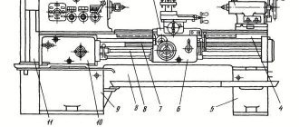
In mechanical engineering, along with cylindrical ones, parts with conical surfaces in the form of external cones or in the form of conical holes are widely used. For example, the center of a lathe has two outer cones, one of which serves to install and secure it in the conical hole of the spindle; a drill, countersink, reamer, etc. also have an outer cone for installation and fastening. The adapter sleeve for fastening drills with a conical shank has an outer cone and a conical hole
Read also: How to check a circuit with a tester
The concept of a cone and its elements
Elements of a cone. If you rotate the right triangle ABC around the leg AB (Fig. 202, a), then a body ABG is formed, called a full cone
.
Line AB is called the axis or altitude of the cone
, line AB is called
the generator of the cone
.
Point A is the vertex of the cone
.
When the leg BV rotates around the axis AB, a circle surface is formed, called the base of the cone
.
The angle VAG between the lateral sides AB and AG is called the cone angle
and is denoted by 2α.
Half of this angle formed by the lateral side AG and the axis AB is called the cone angle
and is denoted α. Angles are expressed in degrees, minutes and seconds.
If we cut off its upper part from a complete cone with a plane parallel to its base (Fig. 202, b), we obtain a body called a truncated cone
.
It has two bases, upper and lower. The distance OO1 along the axis between the bases is called the height of the truncated cone
. Since in mechanical engineering we mostly have to deal with parts of cones, i.e. truncated cones, they are usually simply called cones; From now on we will call all conical surfaces cones.
The connection between the elements of the cone. The drawing usually indicates three main dimensions of the cone: the larger diameter D, the smaller diameter d and the height of the cone l (Fig. 203).
Sometimes the drawing indicates only one of the cone diameters, for example, the larger D, the cone height l and the so-called taper. Taper is the ratio of the difference between the diameters of a cone and its length. Let us denote the taper by the letter K, then
If the cone has dimensions: D = 80 mm, d = 70 mm and l = 100 mm, then according to formula (10):
This means that over a length of 10 mm the diameter of the cone decreases by 1 mm or for every millimeter of the length of the cone the difference between its diameters changes by
Sometimes on the drawing, instead of the angle of the cone, the slope of the cone
. The slope of the cone shows the extent to which the generatrix of the cone deviates from its axis. The slope of the cone is determined by the formula
where tan α is the slope of the cone; D is the diameter of the large base of the cone in mm; d is the diameter of the small base of the cone in mm; l is the height of the cone in mm.
Using formula (11), you can use trigonometric tables to determine the angle a of the cone.
Cone slope and taper are usually expressed as a simple fraction, for example: 1: 10; 1:50, or a decimal fraction, for example, 0.1; 0.05; 0.02, etc.
Methods for producing conical surfaces on a lathe
On a lathe, processing of conical surfaces is carried out in one of the following ways: a) turning the upper part of the support; b) transverse displacement of the tailstock body; c) using a cone ruler; d) using a wide cutter.
3. Machining conical surfaces by turning the upper part of the caliper
When making short external and internal conical surfaces with a large slope angle on a lathe, you need to rotate the upper part of the support relative to the axis of the machine at an angle α of the cone slope (see Fig. 204). With this method of operation, feeding can only be done by hand, rotating the handle of the lead screw of the upper part of the support, and only the most modern lathes have a mechanical feed of the upper part of the support.
To set the upper part of the caliper 1 to the required angle, you can use the divisions marked on the flange 2 of the rotating part of the caliper (Fig. 204). If the slope angle α of the cone is specified according to the drawing, then the upper part of the caliper is rotated together with its rotating part by the required number of divisions indicating degrees. The number of divisions is counted relative to the mark marked on the bottom of the caliper.
If the angle α is not given in the drawing, but the larger and smaller diameters of the cone and the length of its conical part are indicated, then the value of the caliper rotation angle is determined by formula (11)
The method of turning conical surfaces by turning the upper part of the caliper has the following disadvantages: it usually allows the use of only manual feed, which affects labor productivity and the cleanliness of the machined surface; allows you to grind relatively short conical surfaces limited by the stroke length of the upper part of the caliper.
Machining of conical surfaces using the method of transverse displacement of the tailstock housing
To obtain a conical surface on a lathe, when rotating the workpiece, it is necessary to move the tip of the cutter not parallel, but at a certain angle to the axis of the centers. This angle must be equal to the slope angle α of the cone. The simplest way to obtain the angle between the axis of the centers and the direction of feed is to shift the line of centers by moving the back center in the transverse direction. By shifting the rear center towards the cutter (toward itself) as a result of grinding, a cone is obtained, the larger base of which is directed towards the headstock; when the rear center is shifted in the opposite direction, i.e., away from the cutter (away from you), the larger base of the cone will be on the side of the tailstock (Fig. 205).
The displacement of the tailstock body is determined by the formula
where S is the displacement of the tailstock body from the axis of the headstock spindle in mm; D is the diameter of the large base of the cone in mm; d is the diameter of the small base of the cone in mm; L is the length of the entire part or the distance between centers in mm; l is the length of the conical part of the part in mm.
The tailstock housing is shifted using divisions 1 (Fig. 206) marked on the end of the base plate, and mark 2 on the end of the tailstock housing.
If there are no divisions at the end of the plate, then move the tailstock body using a measuring ruler, as shown in Fig. 207.
Read also: Metals with low thermal conductivity
The advantage of machining conical surfaces by displacing the tailstock body is that this method can be used to turn long cones and grind with mechanical feed.
Disadvantages of this method: inability to bore conical holes; loss of time for rearranging the tailstock; the ability to process only shallow cones; misalignment of the centers in the center holes, which leads to rapid and uneven wear of the centers and center holes and causes defects during the secondary installation of the part in the same center holes.
Uneven wear of the center holes can be avoided if a special ball center is used instead of the usual one (Fig. 208). Such centers are mainly used when processing precision cones.
5. Machining conical surfaces using a conical ruler
For machining conical surfaces with a slope angle of up to 10-12°, modern lathes usually have a special device called a cone ruler. The scheme for processing a cone using a cone ruler is shown in Fig. 209.
A plate 11 is attached to the machine bed, on which a conical ruler 9 is mounted. The ruler can be rotated around pin 8 at the required angle a to the axis of the workpiece. To secure the ruler in the required position, two bolts 4 and 10 are used. A slider 7 slides freely along the ruler, connecting to the lower transverse part 12 of the caliper using a rod 5 and a clamp 6. So that this part of the caliper can slide freely along the guides, it is disconnected from the carriage 3 by unscrewing the cross screw or disconnecting its nut from the caliper.
If you give the carriage a longitudinal feed, then the slider 7, captured by the rod 5, will begin to move along the ruler 9. Since the slider is attached to the transverse slide of the caliper, they, together with the cutter, will move parallel to the ruler 9. Thanks to this, the cutter will process a conical surface with an inclination angle , equal to the angle α of rotation of the conical ruler.
After each pass, the cutter is set to the cutting depth using the handle 1 of the upper part 2 of the caliper. This part of the caliper must be rotated 90° relative to the normal position, i.e., as shown in Fig. 209.
If the diameters of the bases of the cone D and d and its length l are given, then the angle of rotation of the ruler can be found using formula (11).
Having calculated the value of tan α, it is easy to determine the value of angle α using the table of tangents. The use of a cone ruler has a number of advantages: 1) setting up the ruler is convenient and quick; 2) when switching to processing cones, there is no need to disrupt the normal setup of the machine, i.e., there is no need to move the tailstock body; the centers of the machine remain in the normal position, i.e. on the same axis, due to which the center holes in the part and the centers of the machine do not work; 3) using a conical ruler, you can not only grind the outer conical surfaces, but also bore conical holes; 4) it is possible to work with a longitudinal self-propelled machine, which increases labor productivity and improves the quality of processing.
The disadvantage of a tapered ruler is the need to disconnect the caliper slide from the cross feed screw. This drawback is eliminated in the design of some lathes, in which the screw is not rigidly connected to its handwheel and the gear wheels of the transverse self-propelled machine.
Machining conical surfaces with a wide cutter
Machining of conical surfaces (external and internal) with a short cone length can be done with a wide cutter with a plan angle corresponding to the slope angle α of the cone (Fig. 210). The cutter feed can be longitudinal or transverse.
However, the use of a wide cutter on conventional machines is only possible with a cone length not exceeding approximately 20 mm. Wider cutters can only be used on particularly rigid machines and parts if this does not cause vibration of the cutter and the workpiece.
7. Boring and reaming of tapered holes
Machining tapered holes is one of the most difficult turning jobs; it is much more difficult than processing external cones.
The machining of conical holes on lathes is in most cases carried out by boring with a cutter with turning the upper part of the support and, less often, using a tapered ruler. All calculations associated with turning the upper part of the caliper or the tapered ruler are performed in the same way as when turning the outer conical surfaces.
If the hole must be in solid material, then first a cylindrical hole is drilled, which is then bored into a cone with a cutter or machined with conical countersinks and reamers.
To speed up boring or reaming, you should first drill a hole with a drill, diameter d, which is 1-2 mm less than the diameter of the small base of the cone (Fig. 211, a). After this, the hole is drilled with one (Fig. 211, b) or two (Fig. 211, c) drills to obtain steps.
After finishing boring the cone, it is reamed using a conical reamer of the appropriate taper. For cones with a small taper, it is more profitable to process the conical holes immediately after drilling with a set of special reamers, as shown in Fig. 212.
Cutting modes when processing holes with conical reamers
Conical reamers work under more difficult conditions than cylindrical reamers: while cylindrical reamers remove a slight allowance with small cutting edges, conical reamers cut the entire length of their cutting edges located on the generatrix of the cone. Therefore, when working with conical reamers, feeds and cutting speeds are used less than when working with cylindrical reamers.
When processing holes with conical reamers, the feed is done manually by rotating the tailstock handwheel. It is necessary to ensure that the tailstock quill moves evenly.
Feed when reaming steel is 0.1-0.2 mm/rev, when reaming cast iron 0.2-0.4 mm/rev.
The cutting speed when reaming conical holes with high-speed steel reamers is 6-10 m/min.
Read also: How to restore a lithium battery after a deep discharge
Cooling should be used to facilitate the operation of conical reamers and to obtain a clean, smooth surface. When processing steel and cast iron, an emulsion or sulfofresol is used.
Measuring conical surfaces
The surfaces of the cones are checked with templates and gauges; measuring and simultaneously checking the angles of the cone is carried out using protractors. In Fig. 213 shows a method for checking a cone using a template.
The outer and inner corners of various parts can be measured with a universal goniometer (Fig. 214). It consists of a base 1, on which the main scale is marked on an arc 130. A ruler 5 is rigidly attached to the base 1. Sector 4 moves along the arc of the base, carrying a vernier 3. A square 2 can be attached to the sector 4 by means of a holder 7, in which, in turn, a removable ruler 5 is fixed. The square 2 and the removable ruler 5 have ability to move along the edge of sector 4.
Through various combinations in the installation of the measuring parts of the protractor, it is possible to measure angles from 0 to 320°. The reading value on the vernier is 2′. The reading obtained when measuring angles is made using the scale and vernier (Fig. 215) as follows: the zero stroke of the vernier indicates the number of degrees, and the vernier stroke, which coincides with the stroke of the base scale, indicates the number of minutes. In Fig. 215 the 11th stroke of the vernier coincides with the stroke of the base scale, which means 2'X 11 = 22'. Therefore, the angle in this case is 76°22′.
In Fig. 216 shows combinations of measuring parts of a universal protractor, allowing the measurement of various angles from 0 to 320°.
For more accurate testing of cones in mass production, special gauges are used. In Fig. 217, and shows a conical bushing gauge for checking outer cones, and in Fig. 217, b—conical plug gauge for checking conical holes.
On the gauges, ledges 1 and 2 are made at the ends or marks 3 are applied, which serve to determine the accuracy of the surfaces being checked.
On the. rice. 218 provides an example of checking a conical hole with a plug gauge.
To check the hole, a gauge (see Fig. 218), which has a ledge 1 at a certain distance from the end 2 and two marks 3, is inserted with light pressure into the hole and checked to see if the gauge is swinging in the hole. No wobble indicates that the cone angle is correct. Once you are sure that the angle of the cone is correct, proceed to check its size. To do this, observe to what point the gauge will enter the part being tested. If the end of the part's cone coincides with the left end of ledge 1 or with one of the marks 3 or is between the marks, then the dimensions of the cone are correct. But it may happen that the gauge enters the part so deeply that both marks 3 enter the hole or both ends of the ledge 1 come out of it. This indicates that the hole diameter is larger than specified. If, on the contrary, both risks are outside the hole or none of the ends of the ledge come out of it, then the diameter of the hole is less than the required one.
To accurately check the taper, use the following method. On the surface of the part or gauge to be measured, draw two or three lines with chalk or a pencil along the generatrix of the cone, then insert or put the gauge on the part and turn it part of the turn. If the lines are erased unevenly, this means that the cone of the part is not processed accurately and needs to be corrected. The erasing of lines at the ends of the gauge indicates an incorrect taper; the erasing of the lines in the middle part of the caliber shows that the taper has a slight concavity, which is usually caused by the inaccurate location of the tip of the cutter along the height of the centers. Instead of chalk lines, you can apply a thin layer of special paint (blue) to the entire conical surface of the part or gauge. This method gives greater measurement accuracy.
Defects in the processing of conical surfaces and measures to prevent them
When processing conical surfaces, in addition to the mentioned types of defects for cylindrical surfaces, the following types of defects are additionally possible: 1) incorrect taper; 2) deviations in the dimensions of the cone; 3) deviations in the diameters of the bases with the correct taper; 4) non-straightness of the generatrix of the conical surface.
1. Incorrect taper is mainly due to inaccurate tailstock housing misalignment, inaccurate rotation of the upper part of the caliper, incorrect installation of the taper ruler, incorrect sharpening or installation of the wide cutter. Therefore, by accurately positioning the tailstock housing, the upper part of the caliper or the cone ruler before starting processing, defects can be prevented. This type of defect can be corrected only if the error along the entire length of the cone is directed into the body of the part, that is, all the diameters of the bushing are smaller, and those of the conical rod are larger than required.
2. The wrong size of the cone at the correct angle, i.e., the wrong size of the diameters along the entire length of the cone, occurs if not enough or too much material is removed. Defects can be prevented only by carefully setting the cutting depth along the dial on finishing passes. We will correct the defect if not enough material was filmed.
3. It may turn out that with the correct taper and exact dimensions of one end of the cone, the diameter of the second end is incorrect. The only reason is failure to comply with the required length of the entire conical section of the part. We will correct the defect if the part is too long. To avoid this type of defect, it is necessary to carefully check its length before processing the cone.
4. Non-straightness of the generatrix of the cone being processed is obtained when the cutter is installed above (Fig. 219, b) or below (Fig. 219, c) the center (in these figures, for greater clarity, the distortions of the generatrix of the cone are shown in a greatly exaggerated form). Thus, this type of defect is the result of the inattentive work of the turner.
Cone figure
Let us give the most general definition of a cone. This figure is understood as a surface that is formed as a result of connecting straight segments of a certain point in space with all points of a given curve. In this case, the specified point in space should not be in the plane of the curve. For example, if the curve has the shape of a parabola, then the figure obtained in the described way will be called a parabolic cone, if the curve is an ellipse, then the cone will be elliptical, and so on.
Having given a geometric definition of what a cone is, we present a photo that clearly shows the possible shapes of this figure.
Looking at this photo, many saw it as the shape of a child's hat worn by Pinocchio, an ice cream cone shaped like a cone, or a warning orange and black striped traffic cone.
Cone volume
Cone volume
equal to a third of the product of the area of its base and its height.
Cone volume formulas:
| V= | 1 | π R2h |
| 3 |
| V= | 1 | Soh |
| 3 |
where V is the volume of the cone, So is the area of the base of the cone, R is the radius of the base of the cone, h is the height of the cone, π = 3.141592.
What is this - a cone?
From the point of view of geometry, we are talking about a spatial figure, which is formed by a set of straight segments connecting a certain point in space with all points of a smooth plane curve. This curve can be a circle or an ellipse. The picture below shows a cone.
You may be interested in:Soviet things: photos and descriptions
The presented figure does not have volume, since the walls of its surface have an infinitesimal thickness. However, if we fill it with a substance and limit it from above not with a curve, but with a flat figure, for example a circle, then we will get a solid volumetric body, which is also usually called a cone.
The cone shape can often be found in life. Thus, it is possessed by ice cream cones or striped black and orange traffic cones, which are placed on the roadway to attract the attention of traffic participants.
Solving problems on the topic “Cone”
Example 1 (Yashchenko 36 options, 2022, option 7)
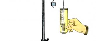
In a cone-shaped vessel, the liquid level reaches 0.25 times the height. The volume of liquid is 5 ml. How many milliliters of liquid must be added to completely fill the container?
Solution:
The volume of the cone is calculated by the formula:
The height of the poured liquid is 0.25 of the entire height of the cone. This means the height is 4 times greater. But at the same time, do not forget that the radius of the entire cone will also increase 4 times. Since we get the case of similar triangles on the axial section:
Taking into account such changes, our new volume (the volume of the entire cone) will take the form:
We see that the volume of the entire cone is 64 times greater than the poured liquid. So, in milliliters it will be:
It turns out that you need to add 315 milliliters.
Answer:
315
Example 2 (Yashchenko 36 options, 2022, option 11)
The cylinder and cone have a common base and height. The volume of the cylinder is 162. Find the volume of the cone.
Solution:
The formulas for the volumes of a cylinder and a cone differ slightly.
We see that the only difference is in the fraction 1/3 in the formula for the volume of a cone. And since, according to the condition, the height and bases coincide, then the volume of the cone will simply be 3 times less. So it is equal to 54.
Answer:
54
Geometric elements that make up a cone
To better understand the question of what a cone is, the geometric names of the elements of this spatial figure should be given.
The cone is limited by two surfaces. The first is called the base. It represents a plane that is limited by the curve noted above. For example, it could be a circle or an ellipse. The second surface is the lateral surface of the figure and is called conical. It does not lie in one plane, but can be turned into a flat figure, as will be discussed below.
One of the important elements of a cone is its apex. This point limits the conical surface. All points of the base curve are connected to it.
The segment that connects the vertex to the base is called the generatrix, or the generatrix of the cone. In turn, the curve limiting the base is called the directrix, or guide figure.
The areas of the conical surface and base add up to the total area of the cone. The volume of space that is bounded by these two surfaces is the volume of the cone.
Surface area
When studying the surface of any three-dimensional figure, it is convenient to use its development onto a plane. Cone is no exception. For a circular cone, the development is shown below.
We see that the development of the figure consists of two parts:
- The circle that forms the base of the cone.
- A sector of a circle, which is the conical surface of a figure.
The area of a circle is easy to find, and the corresponding formula is known to every schoolchild. Speaking about the circular sector, note that it is part of a circle with radius g (the length of the cone generator). The arc length of this sector is equal to the circumference of the base. These parameters make it possible to unambiguously determine its area. The corresponding formula is:
S = pi*r2 + pi*r*g.
The first and second terms in the expression are the cone base and lateral surface area, respectively.
If the length of the generatrix g is unknown, but the height h of the figure is given, then the formula can be rewritten as:
S = pi*r2 + pi*r*√(r2 + h2).
Figure volume
If we take a straight pyramid and increase the number of sides of its base at infinity, then the shape of the base will tend to a circle, and the side surface of the pyramid will approach a conical surface. These considerations allow us to use the formula for the volume of a pyramid when calculating a similar value for a cone. The volume of a cone can be found using the formula:
V = 1/3*h*So.
This formula is always valid, regardless of what the base of the cone is, having area So. Moreover, the formula is also applicable for an inclined cone.
Since we are studying the properties of a straight figure with a round base, we can use the following expression to determine its volume:
V = 1/3*h*pi*r2.
The validity of the formula is obvious.
Volume of a cone in terms of radius
This triangle
to obtain a cone it must rotate around one of its
legs
, which is not only the axis of rotation, but also the height of the cone.
The second
leg becomes the radius of the circle-base of the cone obtained as a result of rotation, and the hypotenuse will be the apothem (the height lowered at a right angle to the line of the circle, and not the center).
Technical cone
with a cylinder is identical to the relationship between a pyramid and a cube (parallelepiped), the only thing is that the derivation
of the formula
goes through the relationship of the integrals of their spherical angles, but nevertheless, just like a pyramid, it occupies one third of the cylinder into which it can be inscribed.
Therefore its volume
is equal to the product of the area of the base and the height divided by three, or the product of the number
π
by the square of the radius and the height divided by three.