In simple words: a block is a wheel with a groove on its circumference. The wheel can rotate around its axis, and a belt or rope can be placed in the groove.
For example, a bicycle wheel can be considered a block if the rubber tire is removed from it and instead of it, a rope, rope, etc. is placed in the groove. A load can be attached to one end of the rope, and a load can be attached to the other end, that is, a force can be applied to it .
If one wants to use a chain instead of a rope, then instead of a wheel with a groove, a wheel with protruding teeth is often used. This eliminates chain slippage and increases traction. Such structures are called asterisks. For example, a bicycle contains two sprockets - one driving, on the axle with pedals, the second - driven, on the axis of the rear wheel.
Blocks are used in various mechanisms, for example, for lifting loads.
Which block is called stationary?
For a stationary block, the axis of rotation does not change its position in space. It is secured to a beam or other support using a special clip (Fig. 70). If a force is applied to the end of the rope thrown over the block, the other end will begin to move upward. If a load of a certain mass is attached to this end, it will rise upward. If a downward force acts on the free end of the rope, then an upward force acts on the load. Measuring these forces shows that they are equal.
What is leverage and when did it begin to be used?
Probably everyone has been familiar with this simple mechanism since childhood. In physics, a lever is a combination of a beam (rod, board) and one support. It serves as a lever for lifting weights or for imparting speed to bodies. Depending on the position of the support under the beam, the lever can lead to a gain in either force or movement of loads. It should be said that leverage does not lead to a reduction in work as a physical quantity; it only allows for the redistribution of its implementation in a convenient way.
Man has been using the lever system for a long time. Thus, there is evidence that it was used by the ancient Egyptians in the construction of the pyramids. The first mathematical description of the lever effect dates back to the 3rd century BC and belongs to Archimedes. A modern explanation of the operating principle of this mechanism involving the concept of moment of force arose only in the 17th century, during the formation of Newton’s classical mechanics.
Why does a stationary block not give a gain in strength?
A stationary block does not provide any gain in force; it only changes the direction of the force.
This feature can be easily explained, given that the fixed block is similar to an equal-arm lever. To do this, move the points of action of the forces upward to points A to B, where the rope touches the block (Fig. 71). The arms of these forces OA and OB will be the same as the radii of the circle. According to the equilibrium condition of the lever, the forces F1 and F2 must also be equal. Experience confirms these conclusions.
- Order solutions to physics problems
Blocks. The golden rule of mechanics
Blocks. The golden rule of mechanics
"The thinking mind does not feel happy,
until he manages to tie together the disparate
facts observed by him"
D. de Hevesy
This topic is dedicated to the study of blocks. And also consideration of the “Golden Rule of Mechanics”.
Previous topics have talked about simple mechanisms such as levers. Lever arm
is
any rigid body that can rotate relative to a fixed support or axis.
There are two types of levers - the lever of the first
and a
second- class
.
A lever of the first kind
is a lever whose axis of rotation is located between the points of application of forces, and the forces themselves are directed in one direction.
A lever of the second type
is a lever whose axis of rotation is located on one side of the points of application of forces, and the forces themselves are directed opposite to each other.
We derived the equilibrium condition for the lever
, according to which
the lever is in equilibrium provided that the forces applied to it are inversely proportional to the lengths of their arms.
Considered the moment of force
-
a physical quantity equal to the product of the modulus of the force rotating the body and its shoulder.
And they formulated the condition for equilibrium of a lever through
the rule of moments
, according to which,
a lever under the action of two forces creating moments is in equilibrium if the moment of the force rotating the lever clockwise is equal to the moment of the force rotating the lever counterclockwise.
a simple block is often used to lift loads
or
block system
.
The blocks are especially often used on construction sites, ports and warehouses. Any block is a wheel with a groove, mounted in a holder
.
A rope, cable or chain is passed along the block gutter.
What types of blocks are there? And how do they transform power?
If the axis of the block is fixed and when lifting loads it does not fall or rise, then the block is called
stationary
.
Such a block can be considered as an equal-arm lever
, in which the arms of the forces are equal to the radius of the wheel. Does such a block give a gain in power? Let's do an experiment. Let's take a load weighing 3 N and hang it from one end of a thread thrown over a block, and attach a dynamometer to the other. With a uniform lifting of the load, the dynamometer will show a force equal to the weight of the load, i.e. 3 N. Let us schematically depict the forces acting on the block.
This is the elastic force of the thread, equal to the weight of the load, the elastic force of the thread, equal to the force applied to the dynamometer, the force of gravity acting on the block and the elastic force of the block axis. As can be seen from the figure, the shoulders of gravity and elasticity of the block are equal to zero. This means that their moments about the axis are equal to zero. The elastic force arms of the thread one and two are equal to each other as the radii of the block. In the equilibrium state of the block, moments of force F
1 and
F
2 must be equal.
And since the moments of these forces are equal, then the forces themselves are equal to each other. In other words, the force applied is equal to the weight of the load. Thus, a stationary block does not provide a gain in force, but only changes its direction
.
Why use a stationary block if there is no gain in strength? After all, with the same success one could use any crossbar to lift the load
. It’s possible, but it’s a losing proposition, since you’ll have to overcome the frictional force of the rope sliding along the crossbar, which is significantly greater than the rolling friction force in the block bearing.
But can a block still provide a gain in strength?
Let's consider another type of block -
a moving
block.
A block is called movable, the axis of rotation of which, when lifting a load, moves along with the load.
We will hang a load weighing 6 N from such a block. We will fasten one end of the thread thrown over the block, and we will evenly lift the load behind the other using a dynamometer. The dynamometer shows that the force applied to the end of the rope is 3 N, i.e., half the weight of the load. Consequently, the movable block gives a gain in strength of approximately 2 times
.
Why?
The block is acted upon by the weight of the load, the elastic forces of the thread, which are equal to each other, and the force of gravity of the block. In this case, most often, the gravity of the block is neglected, since it is usually much less than the weight of the load. When the load moves, the movable block rotates relative to point D. Therefore, the movable block is a lever of the second kind.
Let us write the equilibrium condition for it through the rule of moments. It can be seen from the figure that the arm of the weight of the load is equal to the radius of the block, and the arm of the second force is equal to two radii of the block.
Taking into account that the force F
2 is equal to the force
F
applied to the end of the rope, and using the basic property of proportion, we get
Thus, we can conclude that the movable block gives a double gain in strength
.
Now we can draw the main conclusion that when using simple mechanisms, we can get a gain in power
.
A logical question arises: Is it possible to get a win in work using a simple mechanism?
?
If the applied force is less than the weight of the load, will the work done by it be less than the work done to lift the load without using a mechanism?
Let's do an experiment. We will lift the load uniformly to a certain height using a movable block (we neglect the gravity of the block and the friction force).
The work done by a force applied to a thread is equal to the product of the force applied to the thread and the height of its point of application.
As can be seen from the figure, the height of the lifting point of the force application is twice the height of the lifting load. The work of lifting a load is equal in modulus to the product of the weight of the load and the height of the lift.
Now let's compare the two works. At the same time, we take into account that the force applied to the end of the rope is approximately two times less than the weight of the load.
Taking this fact into account, we find that the work of lifting the load is equal to the work of the force applied to the thread
.
Thus, the use of a moving block does not provide any gain in operation
. Since, there is a gain of 2 times in strength and a loss of 2 times on the way.
You can approach the consideration of leverage in a similar way. To do this, 2 forces of different magnitude are balanced on the lever, and the lever is set in motion.
If we measure the distances traveled by the larger and smaller forces, and the modules of these forces, we find that the paths traveled by the points of application of forces on the lever are inversely proportional to the forces
.
Thus, as in the case of the moving block, we can conclude that by acting on the long arm of the lever, we gain in strength, but at the same time we lose the same number of times along the way.
Since the product of force and path is work, then in this case,
there is no gain in work.
As centuries-old practice has shown, not a single mechanism gives a gain in work
.
This statement is called the “Golden Rule of Mechanics.”
If, with the help of some simple mechanism, we win in strength, then we lose by the same amount along the way. Is it possible to establish strict equality between them when comparing works? After all, when making this or that conclusion, a condition was introduced that the force of gravity acting on the block and the friction force in the block can be neglected?
However, friction exists.
It is present in all mechanisms. And there is also a force of gravity that acts on the block itself, even if it is small. Even if there is no lifting of a simple mechanism or its parts (as in the case of a stationary block), it is necessary to apply additional force to set it in motion, that is, to overcome the inertia of the mechanism. Therefore, the force applied to the mechanism must actually do more work than the useful work of lifting the load.
The work of force applied to the mechanism is called expended
or
full time work
.
And the useful
work is to lift only the load itself.
If we consider any mechanism, then the useful work is always only a certain part of the total work
.
Let us denote the useful work as A
P, and the expended work as
A
3.
The ratio of useful work to work expended is called the efficiency of the mechanism
(abbreviated as efficiency).
Efficiency is denoted by the small Greek letter h (eta) and is most often expressed as a percentage. Since useful work
always less than perfect work
, the efficiency of the mechanism is always less than 100%.
Exercises.
Task 1.
What is the minimum force required at the end of the rope to lift a 50 kg bag of cement using a moving pulley? To what height will the bag be raised when 2500 J of work is performed by this force?
Task 2.
A slab weighing 120 kg was uniformly raised using a moving block to a height of 16 m in a period of time equal to 40 s. Assuming the efficiency to be 80% and the mass of the block to be 10 kg, determine the total work and the developed power.
Main conclusions:
– Block
- this is one of the types of lever, which is a wheel with a groove mounted in a cage. There are movable and fixed blocks.
– Fixed block
- this is a block whose axis of rotation is fixed and when lifting loads it does not rise or fall.
– Movable block
is a block whose axis of rotation rises and falls along with the load.
– A stationary block
does not give a gain in strength, but only changes its direction.
– Movable block
, if we neglect friction and the weight of the block itself,
the gain in strength
is doubled.
– "The Golden Rule of Mechanics"
, according to which the number of times we win in strength, the same number of times we lose on the road.
– Efficiency
mechanism shows what part of the total applied force is useful work.
– Useful work
always
less than perfect
.
The efficiency of any mechanism is less than 100%.
Which block is called movable?
A block whose axis moves in space is called movable. When using such a block, one end of the rope or cable is usually secured to a support, and the load is secured to the clip in which the block is secured. Figure 72 shows an experiment with such a block. A load weighing 102 g is suspended from the axis of a light moving block. So, a force of 1 N acts on the axis of the block. The needle of a dynamometer attached to the free end of the rope shows approximately 0.5 N. Some small differences are due to the fact that the block itself has weight and a frictional force acts on it.
Why does a moving block give a gain in strength?
This feature of the movable block can be explained by taking into account the properties of the lever (Fig. 73). The block disk can be considered a lever of length 2R (where R is the radius of the wheel). The axis of rotation of such a lever passes through point A on the wheel rim, and the points of application of forces are points O and B. Since the properties of blocks described above are used when solving practical problems.
Conditions for displaying formulas
Let's simplify the task of obtaining formulas for blocks. We will consider the block ideal.
Let some conditions be met for this:
- We consider the block weightless, that is, it has no mass,
- We believe that the block is absolutely rigid, that is, there is no deformation,
- There is no friction when the block rotates.
Explanations of the conditions
These three conditions are necessary to ensure that our efforts are spent only on moving the payload, and not on rotating the block. We attach the load to one end of the rope while we pull on the other end.
In more strict language: the conditions must be met so that the applied force does only work to move the payload, and energy is not expended on rotating the block.
To be honest, in reality nothing ideal exists and all these conditions cannot be fully met. The blocks are made of durable metals, and they have mass. Friction can only be reduced, but it cannot be completely eliminated. But, since the mass of the block is small compared to the load being lifted and friction is significantly reduced, in this article we will consider the block ideal.
Let's consider such ideal blocks.
Difference between block and roller
These are closely related concepts that are often used colloquially as synonyms. In fact, there is a difference between them. So, the roller is directly the wheel itself with a groove around its circumference. Essentially this is the same pulley that is used to operate the drive belt. The block is a more complex design. It is a roller installed in the housing. In its minimal design, the latter is a fork with an axle inserted between its halves. The roller itself rotates on it. Thanks to the presence of the housing, the unit can be suspended and also moved.
Examples of the use of simple mechanism systems
In fact, any machines that surround us are systems of levers and pulleys. Here are the most famous examples:
- typewriter;
- piano;
- lifting crane;
- folding scaffolding;
- adjustable beds and tables;
- a collection of human bones, joints and muscles.
If the input force in each of these systems is known, then the output force can be calculated by sequentially applying the lever rule to each element of the system.
Blocks. Efficiency of moving and non-moving blocks
Blocks are simple mechanical devices that allow you to regulate force. Any block is a wheel with a groove around its circumference, rotating around its axis. If the axis is fixed, then the block is called fixed
.
If the axis is movable, then the block is called movable
. The groove is designed for rope, chain, belt, etc.
Fixed block.
- The action of a fixed block is similar to the action of a lever with equal arms l1=l2=r
.
The applied force F1
is equal to the load
F2
, and the equilibrium condition is: - F1 = F2.
- A fixed block is used when you need to change the direction of a force without changing its magnitude.
- Movable block.
The moving block acts similarly to a lever whose arms are: l2 = l1 /2 = r
. In this case, the equilibrium condition has the form:
where F1
— applied force,
F2
— load. The use of a moving block gives a double gain in strength.
- Calculation of a shoe brake driven by an electrohydraulic pusher.
- Calculation diagram of the TKT shoe brake with spring closure
- Rice. 1
- Maximum permissible installation gap between block and pulley:
- where hm is the stroke of the electromagnet armature; k1 is the coefficient of possible use of the armature stroke.
- From the equilibrium condition of the upper lever connecting the right lever with the closing spring and with the pusher rod, the required spring compression force is determined:
When the brake is released, the force of the pusher P overcomes the compression force of the spring Pp; in this case Рт = Рпc/e.
The required stroke of the pusher rod ht is determined from the equation:
- In Figure 2, size ht is the full stroke of the rod indicated in the passport, size h is the installation working stroke of the rod.
- Shoe brake with electro-hydraulic drive
- Rice. 2
- The values of the minimum radial installation gaps between the block and the pulley are taken according to the following recommendations:
- Table 1
The rigidity of the lever system must be checked by calculation. The total deformation of the lever system, regardless of the type of drive, should not be more than 10% of the normal stroke of the rod.
Calculation of brake levers for strength is carried out based on the bending moment M from the force P in the dangerous section of the lever:
where W is the moment of resistance to bending of the calculated section of the lever; kd is a dynamic coefficient that takes into account the nature of the change in the applied force when closing the brake, and depending on the type of shoe brake drive (see stops and brakes) has the following values:
GPM cargo drums. Calculation of drum dimensions for multiple rope windings.
Drums
- these are elements of lifting machines that serve to wind a flexible member and convert the rotational movement of the drive into the translational movement of the load.
Drums are divided into chain and rope for single and double pulley hoists.
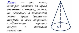
, rope drums are divided into cylindrical and conical
and
conoidal.
The most common are cylindrical drums. They are smooth and cut.
Smooth drums are used for multi-layer rope winding at high lifting heights and the need to reduce the length of the drum according to the layout conditions.
However, for ropes wound on smooth drums, large contact stresses appear at the points of contact and the rope flattens when wound in several layers, which significantly reduces their service life.
Drums are made by casting or welding.
The thickness of the drum wall is taken according to the empirical relationship: d = 0.02 D + (6 10) mm - for cast iron drums and d = 0.01 D + 3 mm - for steel ones, where D is the diameter of the drum along the bottom of the groove, mm
CALCULATION
With the same length of rope, multilayer winding allows the use of drums of shorter length than with single-layer winding, however, the operating conditions of the rope in this case sharply deteriorate, its service life is reduced, and uniform movement of the load is not ensured; the speed of movement of the load is different when winding the first and each of the subsequent layers. Drums for multilayer winding are made with a smooth surface and sides that prevent the rope from coming off. Side height ho :
- h0=(m+2)dК
- where h0 is the height of the drum sides; dк - rope diameter ;
- For a given rope capacity LK
, rope diameter
dK
, drum diameter
DB
, winding pitch equal to
dK
, number of wound layers
m
,
drum length with a smooth surface:
- LB=LКdК/
π
m(mdК+DB) - The rope capacity of the drum depends on the length and diameter of the drum LB
and
DB
, the number of layers of rope winding on the drum
m
and the diameter of the rope
dк
, which are selected from the passport.
Rope capacity is determined, m - LК=(πzm( DB dК)-2π DB )/1000
- where z
is the number of rope turns on the working length of the drum,
z
=
LB
/
t
;
t
is the rope winding pitch,
t
=
d
.
Source: https://infopedia.su/1x1b6.html
Block system - theory ↑
The invention of the chain hoist gave a huge impetus to the development of civilizations. The block system helped build huge structures, many of which have survived to this day and puzzle modern builders. Shipbuilding also improved, and people were able to travel great distances. It's time to figure out what it is - a chain hoist and find out where it can be used today.
Structure of the lifting mechanism ↑
A classic chain hoist is a mechanism that consists of two main elements:
A pulley is a metal wheel that has a special groove for a cable along its outer edge. An ordinary cable or rope can be used as a flexible connection. If the load is heavy enough, ropes made of synthetic fibers or steel ropes and even chains are used. To ensure that the pulley rotates easily, without jumping or jamming, roller bearings are used. All elements that move are lubricated.
One pulley is called a block. A pulley block is a system of blocks for lifting loads. The blocks in the lifting mechanism can be stationary (rigidly fixed) and movable (when the axis changes position during operation). One part of the pulley is attached to a fixed support, the other to the load. Movable rollers are located on the load side.
The role of the stationary block is to change the direction of movement of the rope and the action of the applied force. The role of the mobile is to gain strength.
The principle of operation - what is the secret ↑
The operating principle of a pulley block is similar to a lever: the force that needs to be applied becomes several times smaller, while the work is performed in the same volume. The role of the lever is played by the cable. In the operation of a chain hoist, the gain in strength is important, so the resulting loss in distance is not taken into account.
Depending on the design of the pulley, the gain in strength may be different. The simplest mechanism of two pulleys gives approximately a twofold gain, of three - threefold, and so on. The increase in distance is calculated using the same principle. To operate a simple pulley, you need a cable twice as long as the lifting height, and if you use a set of four blocks, then the length of the cable increases in direct proportion to four times.
In what areas is the block system used? ↑
A chain hoist is a faithful assistant in a warehouse, in production, and in the transport sector. It is used wherever force needs to be used to move all kinds of loads. The system is widely used in construction.
Despite the fact that most of the heavy work is performed by construction equipment (cranes), the chain hoist has found a place in the design of load-handling mechanisms. The block system (pulley block) is a component of such lifting mechanisms as a winch, hoist, and construction equipment (various types of cranes, bulldozer, excavator).
In addition to the construction industry, pulleys are widely used in organizing rescue operations. The principle of operation remains the same, but the design is slightly modified. Rescue equipment is made of durable rope and carabiners are used. For devices of this purpose, it is important that the entire system is quickly assembled and does not require additional mechanisms.
System of levers and blocks
As mentioned in previous paragraphs, a lever can be used to gain in path or force, while a block allows you to gain in force and change the direction of its action. These properties of the simple mechanisms under consideration are used in systems of levers and blocks. In these systems, each element receives some force and transmits it to other elements so that the output is the original force.
The simplicity of operation of the lever and block and the flexibility of their structural use make it possible to compose complex mechanisms from such a set.
How to make a lift with your own hands ↑
In construction, during installation work, it is not always possible to fit a crane. Then the question arises of how to lift the load with a rope. And here a simple chain hoist finds its application. To make it and fully operate, you need to make calculations, drawings, and choose the right rope and blocks.
Preparation of the base - diagram and drawing ↑
Before you start building a chain hoist with your own hands, you need to carefully study the drawings and choose a suitable scheme for yourself. You should rely on how it will be more convenient for you to place the structure, what blocks and cable are available.
It happens that the lifting capacity of the pulley blocks is not enough, and there is no time or opportunity to build a complex multiple lifting mechanism. Then double chain hoists are used, which are a combination of two single ones. This device can also lift the load so that it moves strictly vertically, without distortions.
How to choose a rope and block ↑
The most important role in building a chain hoist with your own hands is played by the rope. It is important that it does not stretch. Such ropes are called static. Stretching and deformation of a flexible connection causes serious losses in work efficiency. For a homemade mechanism, a synthetic cable is suitable; the thickness depends on the weight of the load.
The material and quality of the blocks are indicators that will provide homemade lifting devices with the calculated load capacity. Depending on the bearings that are installed in the block, its efficiency changes and this is already taken into account in the calculations.
But how can you lift a load to a height with your own hands and not drop it? To protect the load from possible reverse movement, you can install a special locking block that allows the rope to move only in one direction - the desired direction.
Step-by-step instructions for lifting a load through a block ↑
When the rope and blocks are ready, the diagram has been selected, and the calculations have been made, you can begin assembly. For a simple double pulley you will need:
- roller – 2 pcs.;
- bearings;
- bushing – 2 pcs.;
- clip for block – 2 pcs.;
- rope;
- hook for hanging cargo;
- slings - if they are needed for installation.
Step-by-step lifting of the load to a height is carried out as follows:
- Connect the rollers, bushing and bearings. They combine all this into a clip. Get a block.
- The rope is launched into the first block;
- The clip with this block is rigidly attached to a fixed support (reinforced concrete beam, pillar, wall, specially mounted extension, etc.);
- The end of the rope is then passed through the second block (movable).
- A hook is attached to the clip.
- The free end of the rope is fixed.
- They sling the lifted load and connect it to the chain hoist.
The homemade lifting mechanism is ready to use and will provide double the strength benefits. Now, to raise the load to a height, just pull the end of the rope. By bending around both rollers, the rope will lift the load without much effort.
Safe locomotive integrated complex BLOK
February
2 9:26
admin
Category: Locomotive equipment
The issue of ensuring safe traffic is key in railway transport. To solve this problem, designers have created various locomotive safety devices.
Already 40 years ago, automatic locomotive signaling (ALS) and other safety devices began to be installed en masse on the railways of the USSR. In the 90s and 2000s, the introduction of the first integrated security systems (CLUB, CLUB-U, etc.) began in Russia.
Inclined plane.
As we know, it is easier to roll a heavy barrel along inclined walkways than to lift it vertically. The bridges are thus a mechanism that provides gains in strength.
In mechanics, such a mechanism is called an inclined plane. An inclined plane is a flat, flat surface located at a certain angle to the horizontal. In this case, they briefly say: “inclined plane with an angle.”
Let's find the force that must be applied to a mass load in order to uniformly lift it along a smooth inclined plane with an angle . This force, of course, is directed along the inclined plane (Fig. 5).
Let's select the axis as shown in the figure. Since the load moves without acceleration, the forces acting on it are balanced:
.
We project on the axis:
,
where
.
This is exactly the force that needs to be applied to move the load up an inclined plane.
To evenly lift the same load vertically, a force equal to . It can be seen that, since . An inclined plane actually gives a gain in strength, and the smaller the angle, the greater the gain.
Widely used types of inclined plane are wedge and screw.
Applying block combinations
In practice, a combination (system) of fixed and movable blocks is often used (Figure 3). This combination is called a pulley block.
Figure 3. Movable and fixed block combinations.
With this option of using blocks, we also get a 2-fold gain in strength. Provides it with a moving block. Using a stationary block, we change the direction of the force. It allows us to take a more comfortable position - so we can lift the load while standing on the ground.
In practice, the pulley is part of the lifting mechanism of cranes (Figure 4).
Figure 4. Hook suspension with chain hoist.
Climbers use a system of blocks to tension railings and crossings, as well as to lift victims from gorges, cracks, etc. (Figure 5).
Figure 5. Block system in mountaineering.
Leverage rule
On what principle does the lever work? The answer to this question is contained in the concept of moment of force. The latter is the quantity that is obtained by multiplying the force arm by its modulus, that is:
M = F*d
The force arm d is the distance from the fulcrum to the point of application of the force F.
When a lever does its job, three different forces act on it:
- external force applied, for example, by a person;
- the weight of the load that a person seeks to move using a lever;
- support reaction acting from the side of the support on the lever beam.
The support reaction balances the other two forces, so the lever does not move forward in space. To prevent it from also performing rotational motion, it is necessary that the sum of all moments of forces be equal to zero. The moment of force is always measured relative to some axis. In this case, this axis is the fulcrum. With this choice of axis, the leverage of the support reaction force will be equal to zero, that is, this force creates zero moment. The figure below shows a typical first class lever. The arrows indicate the external force F and the weight of the load R.
We write down the sum of moments for these forces, we have:
R*dR + (-F*dF) = 0
The equality of the sum of moments to zero ensures that the lever arms do not rotate. The moment of force F is taken with a negative sign because this force tends to turn the lever clockwise, while force R tends to make this turn counterclockwise.
Rewriting this expression in the following forms, we obtain the equilibrium conditions for the lever:
R*dR = F*dF;
dR/dF = F/R
We obtained the written equalities using the concept of torque. In the 3rd century BC. e. Greek philosophers did not know about this physical concept, however, Archimedes established an inverse relationship between the ratio of the forces acting on the arms of the lever and the length of these arms as a result of experimental observations.
The written equalities indicate that a decrease in the length of the arm dR makes it possible to lift large weights R of loads with the help of a small force F and a long arm dF.
Content
We call a lever any rigid body that can rotate around a fixed support. One of the types of lever is such a simple mechanism as a block.
The block is a wheel (disc) with a groove, mounted in a holder.
A cable, chain or rope is passed through the block chute. If a block is a type of lever, then does the law of equilibrium ($\frac{F_1}{F_2} = \frac{l_2}{l_1}$) apply to it?
In order to answer this question, in this lesson we will study the structure of the block in more detail. There are two types of blocks: movable and fixed. Let's look at the operating principle of each of them.