Shapes of geometric bodies
A part of any shape can be represented as a collection of individual geometric bodies.
For example, let's take a part (Fig. 159.a) and analyze its shape. Mentally dividing it into individual elements, we obtain the following geometric bodies (Fig. 159, b): 1 - a truncated straight circular cone with a cylindrical hole, 2 - a straight circular cylinder, 3 - a rectangular parallelepiped, 4 - two rectangular parallelepipeds with cylindrical holes, 5 - two hollow half-cylinders. To perform complex drawings, it is necessary to master methods for projecting individual geometric bodies, as well as points and lines located on the surface of these bodies.
Rice. 159
Geometric bodies bounded by flat polygons are called polyhedra (Fig. 160, a). These polygons are called faces, and their intersections are called edges. An angle formed by faces converging at one point - a vertex - is called a polyhedral angle.
Bodies of revolution are limited by surfaces that are obtained as a result of the rotation of a line around a fixed axis (Fig. 160, b and c). The line AB, which during its movement forms a surface, is called a generatrix. The most common bodies of rotation are cylinder, cone, ball, and torus.
Rice. 160
Drawing a ball
The geometric shape of a ball is the simplest of all shapes, but for drawing a ball is the most difficult task. First of all, it is difficult for beginners to draw an even circle; it is difficult to achieve smooth tonal transitions when shading, so that the ball in the drawing does not have dents. The ball can be illuminated with natural light from a window or soft light with a diffuser. This light is better, it does not produce harsh shadows.
When illuminated with an incandescent lamp, the contrast is stronger, which often leads to beginners depicting the ball as too dark, as if it were not made of plaster, but of lead.
Below is a finished drawing of the ball. Images of step-by-step work, construction of shadows, explanations of the nature of reflexes will appear on the site later.
After you have mastered the drawing of geometric bodies individually, you can begin to draw a group of geometric bodies. As a rule, the composition includes a cube or parallelepiped, 1-2 bodies of rotation and a ball. Drawing a jug is also done after the student is able to draw simple geometric shapes.
Copying of articles is permitted only if there is an active (clickable) link to the source page of Denis Gavrilov’s website gavrilovart.ru and with attribution. The link must be located directly next to the material, must be visible and direct (without the use of java scripts). It is prohibited to change, erase, or cut off copyrights in photographs or illustrations copied from my site in any way.
Prism projections
The construction of projections of a regular straight hexagonal prism (Fig. 161) begins with the implementation of its horizontal projection - a regular hexagon. From the vertices of this hexagon, vertical communication lines are drawn and a frontal projection of the lower base of the prism is built. This projection is represented by a horizontal line segment. From this straight line upward, the height of the prism is plotted and a frontal projection of the upper base is constructed. Then the frontal projections of the ribs are drawn - segments of vertical straight lines equal to the height of the prism. The frontal projections of the anterior and posterior ribs coincide. Horizontal projections of the side faces are depicted as straight segments. The front side face 1243 is depicted on the V plane without distortion, and on the W plane as a straight line. Frontal and profile projections of the remaining side faces are depicted with distortion.
In the drawing, the x, y and z axes are not shown, which makes the drawing simpler.
Rice. 161
The construction of projections of an inclined prism is somewhat more complicated.
Let's consider the procedure for constructing projections of an inclined hexagonal prism.
1. A prism, the base of which lies on the plane H, is inclined to this plane at angle α (Fig. 162, a). The edges of the prism are parallel to plane V, i.e. are frontal.
First, a horizontal projection of the base of the prism is constructed, which is projected onto the H plane without distortion (regular hexagon). The frontal projection of the base is a straight line segment parallel to the x-axis.
From points 1′, 2′, 3′ of the frontal projection of the base, direct projections of the ribs are drawn at an angle α to the x-axis and the actual length of the side edge of the prism is plotted on them.
Construct a frontal projection of the upper base of the prism in the form of a straight line segment equal and parallel to the frontal projection of the lower base.
From points 1, 2, 3, 4. 5. 6 of the horizontal projection of the lower base, straight lines are drawn - projections of the ribs - parallel to the x-axis and six points are found on them using vertical connection lines - horizontal projections of the vertices of the upper base of the prism.
2. A straight regular hexagonal prism is inclined at an angle α to the plane H. The base of the prism is inclined to the plane H at an angle β (Fig. 162, b).
In this case, it is necessary to first construct a frontal projection of the base. This projection is a segment equal to the distance between the parallel sides of the hexagon. If this segment is divided in half and a connection line is drawn from its middle, then points 2 and 5 will be located on it - horizontal projections of the vertices of the base of the prism. The distance between points 2, 5 is equal to the actual distance between the vertices of the base of the prism. Since the horizontal projections of sides 16 and 34 represent their actual lengths, taking advantage of this circumstance, it is possible to construct a completely horizontal projection of the base.
The further construction process shown in Fig. 162, b, similar to that shown in Fig. 162, a.
Rice. 162
In complex drawings of objects, it is often necessary to construct projections of lines and points located on the surface of these bodies, having only one projection of a line or point. Let's consider the solution to this problem.
A complex drawing of a quadrangular right prism and a frontal projection a' of point A are given.
First of all, you need to find in the complex drawing two projections of the face on which point A is located. In the complex drawing you can see (Fig. 163, a) that point A lies on the face of prism 1265. The frontal projection a' of point A lies on the frontal projection 1' 2'6'5' prism faces. The horizontal projection 1562 of this face is segment 56. On this segment there is a horizontal projection a of point A. The profile projection of the prism and point A is constructed using communication lines.
Using the existing complex drawing of the prism, you can perform its isometric projection along the coordinates of the vertices. To do this, first build the lower base of the prism (Fig. 163, b), and then the vertical ribs and the upper base (Fig. 163, c).
Using the coordinates m and n of point A, taken from a complex drawing, it is possible to construct an axonometric projection of this point.
Rice. 163
Conical surface of revolution
Table of contents:
Conical surface of revolution
Straight circular cone
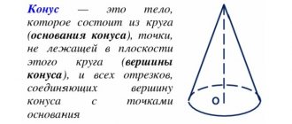
A conical surface of revolution is a ruled surface formed by the rotation of a rectilinear generatrix, which intersects a curved-linear guide (circle) and passes through a fixed point of the axis of rotation, called the vertex.
A cone is a geometric body bounded by a conical surface and a base plane intersecting all its constituents.
A cone is called straight if the axis of rotation is perpendicular to its base. The cone is called circular, since the guide is the circle Cone with two parallel bases, i.e. a cone with a cut off top is called truncated.
Construction of projections of a right circular cone
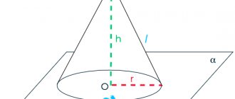
In Fig. Figure 4.71 shows an example of constructing projections of a straight line of a circular cone with a horizontally projecting axis of rotation, a given height and a base of radius.
To construct projections of a cone, it is necessary to perform graphic-analytical actions in the following order:
1st action. According to the given condition, construct a horizontal projection of the outline of a right circular cone, which represents a circle of a given radius with a vertex coinciding with the axis of rotation.
2nd action. Perform a graphical analysis of the constructed horizontal projection of the cone:
- The radius circle is an invisible projection of the base of the cone.
- The circle of radius with the apex of the cone is the visible projection of the lateral surface of the cone.
- Mark on the horizontal projection the characteristic generatrices of the cone and which will determine the outlines of the frontal and profile projections of the cone.
3rd action. Construct a frontal projection (outline) of a cone, which is a triangle of a given height, limited by:
- on the left and right - projections of the lateral outlines and ;
- horizontal segment, which is the projection of the base of the cone;
- frontal projections of characteristic generatrices and, which coincide with the axis of the cone.
4th action. Construct a profile projection (sketch) of a cone:
- 'Set on the circle of the horizontal projection of the cone the position of the base line (b.o.), coinciding with the horizontal line of the axis of this circle.
- Select the position of the base axis (b.o.), which will coincide with the vertical axis of rotation on the profile projection of the cone.
- The profile projection of a cone is a limited triangle:
on the left and right by outline generators and constructed according to the coordinate:
the vertex lying on the base axis; horizontal segment projection of the base;
profile projections of characteristic generators and , which coincide with the axis of rotation of the cone.
!!! Remember the characteristic features of the outlines of a right circular cone in the drawing - a circle at the base and two triangles.
!!! Characteristic features of the outlines of a right circular truncated cone are the base circle and two isosceles trapezoids.
Constructing a projection of points lying on the surface of a cone
The belonging of a point to the surface of a cone is determined by its belonging to the generatrix of the surface and its belonging to the circular parallels (circles) along which the point rotates around the axis of the cone. Consequently, projections of a point can be constructed either by belonging to a generator or by belonging to a circular parallel.
In Fig. Figure 4.71 shows an example of constructing horizontal and profile projections of points and given to frontal projections and but their belonging to circular parallels.
Constructing horizontal projections of given points:
- the horizontal projection of a characteristic point lying on the characteristic generatrix of the cone is determined on the horizontal projection of this generatrix;
horizontal projections of points and are built on auxiliary circular parallels drawn through given frontal projections of points.
Let's consider a graphical algorithm for constructing horizontal projections of points lying on the lateral surface of a cone (using the example of a given point, using their circular parallels, if reliable:
Graphical Algorithm I:
1st action. Draw a frontal projection of an auxiliary circular parallel through a given frontal projection of a point: the projection of a parallel is a straight line perpendicular to the axis of the cone and parallel to its base.
2nd action. Draw a circle of the horizontal projection of the parallel with the resulting radius.
3rd action. Construct a horizontal projection of a point along a vertical connection line on a horizontal projection of a parallel
Repeat the steps of graphical algorithm 1 and similarly construct horizontal projections of points and .
Construction of profile projections of given points. The points and are constructed according to their characteristic generators:
the point lies on a visible characteristic generatrix coinciding with the axis of the cone;
- the point lies on the characteristic generatrix.
- points and are constructed using coordinates.
- point - by coordinate (visible);
- point - by coordinate (invisible).
In Fig. Figure 4.72 shows an example of constructing a horizontal and profile projection of a point based on its belonging to the generatrix.
- The construction of a horizontal projection of a point according to the generatrix is performed using graphical algorithm II:
1st action. Draw an auxiliary generatrix through the vertex of the cone and the given invisible frontal projection of the point
2nd action. Construct a horizontal projection of a generatrix passing through the vertex of the cone and an auxiliary point lying at the base of the cone.
3rd action. Construct a horizontal projection of a point along a vertical connection line based on its belonging to the generatrix.
- The construction of a profile projection of an invisible point is carried out according to the belonging of the generatrix, constructed at the coordinate.
In Fig. Figure 4.72 shows the construction of a frontal and profile projection of a point according to its given horizontal projection. The construction was carried out according to the given algorithms I and II, but in reverse order:
1st action. On the horizontal projection of a cone with a radius, draw a circle of an auxiliary parallel or an auxiliary generatrix on which the horizontal projection of the point lies.
2nd action. Construct frontal projections of an auxiliary parallel or auxiliary generatrix:
draw a parallel through an auxiliary point on the generatrix parallel to the base of the cone;
draw the generatrix through the auxiliary point at the base of the cone and the vertex of the cone
3rd action. Construct a frontal projection of a point along a vertical connection line according to its belonging to either a parallel or a generatrix.
Conic sections
Let us consider five possible cases of the location of the cutting plane relative to the axis of the cone and its generators, which determine the shape of the line of its intersection with the surface of the cone (mathematical proofs are not given):
1st cases. If the secant plane passes through the vertex of the cone, then this plane intersects the conical surface along two generatrices (frontally projecting plane, Fig. 4.73).
2nd case. If the secant plane is located perpendicular to the axis of the cone, then this plane intersects the conical surface of the circle (horizontal plane Fig. 4.73).
3rd case. If the secant plane is located parallel to one generatrix of the cone, then this plane intersects the conical surface along a parabola (the frontally projecting plane is parallel to one generatrix, Fig. 4.74).
4th case. If the secant plane is located parallel to the two generatrices of the cone, then this plane intersects the conical surface along a hyperbola (the frontal plane is parallel to the two generators - and, Fig. 4.75).
5th case. If the plane intersects all the generatrices of the cone at an angle other than a straight line (or otherwise, is not parallel to any generatrix of the cone), then this plane intersects the conical surface along an ellipse (front-projecting plane), Fig. 4.76).
Let us consider constructing an intersection line on the projections of the cone for all five cases of sections.
1st and 2nd cases. In Fig. Figure 4.73 shows the construction of projections of a right circular cone with a cutout formed by sections of the conical surface by a front-projecting plane passing through the apex of the cone (1st case), and a horizontal plane located perpendicular to the axis of the cone (2nd case).
The plane intersects the surface of the cone along generatrices, the horizontal and profile projections of which are constructed using an auxiliary point lying on the base of the cone.
The plane intersects the surface of the cone along a circle of radius limited by the line 3-3 of intersection of the cutout planes.
The construction of horizontal and profile projections of a cone with a cutout and the design of the outlines of these projections can be seen from the drawing.
3rd case. In Fig. Figure 4.74 shows the construction of projections of a cone with a cut by a front-projecting plane located parallel to one generatrix of the cone.
The plane intersects the surface of the cone along a parabola, the horizontal and profile projections of which are constructed using the marked characteristic points 1, 2 and 3 and an intermediate point (not marked)
The projections of these points are constructed according to their affiliation:
- the point lies on the projections of the characteristic generator;
- the points lie on the projections of the characteristic generators and , the horizontal projections of which are constructed using a parallel with a radius (algorithm I);
- points lie on the circle of the base of the cone: the horizontal projections of these points are determined along the connection line on the horizontal projection of the base circle, and their profile projections are plotted along the coordinate ,
- projections of an intermediate point are constructed according to its belonging to the corresponding parallel (profile projections - along the coordinate ).
The design of the projection outlines can be seen from the drawing.
4th case. In Fig. Figure 4.75 shows the construction of projections of a cone with a cut by the frontal plane located parallel to the two generatrices of the cone and .
The plane intersects the surface of the cone along a hyperbola, the frontal projection of which is constructed from marked points 1. 2 and 3 according to their belonging to parallels (inverse algorithm I), and the profile projection of the hyperbola is projected into a vertical line and coincides with the degenerate projection of the cut plane
The design of the projection outlines can be seen from the drawing.
In Fig. 4 75 the profile projection of the cone shows the position of the cutting plane at an angle to the axis of the cone. When the plane also intersects the surface of the cone along a hyperbola.
5th learn. In Fig. Figure 4.76 shows the construction of a projection of a cone with a cut by a front-projecting plane intersecting all the generatrices of the cone at an angle to the axis different from a straight line.
The plane intersects the surface of the cone along an ellipse, the horizontal and profile projections of which are constructed according to the projections of the marked characteristic points 1, 2, 4 and intermediate points 3, taken in the middle of the segment 1-4, which is the coinciding projection of the ellipse and its major axis. Kidneys 3 determine the projections of the minor axis of the ellipse and are built on the horizontal projection of the cone along the radius of the parallel, and on the profile projection but on the coordinate (algorithm I).
The design of the projection outlines can be seen from the drawing.
!!! The number of intermediate points taken should be minimal, but sufficient to construct on the cone projections the shapes of second-order curves (parabolas, hyperbolas and ellipses), which are drawn in the drawing using the constructed characteristic and intermediate points using a pattern.
Constructing a projection of a right cone with cuts by planes of particular position
In Fig. Figure 4.77 shows an example of constructing projections of a right circular cone with cuts by a front-projecting plane and a profile plane.
To construct projections of a cone with slices, you should perform a graphical algorithm that determines the procedure for solving all such problems.
1st action. Construct in the drawing with thin lines along a given radius of the base and height the frontal, horizontal and profile projections of the cone without cuts, and then make the specified cuts on its frontal projection with a front-projecting plane and a profile plane;
2nd action. Mark on the frontal projection the characteristic points of intersection of the cutting planes with the generatrices and the base of the cone and perform a graphical analysis of the sections:
1. The front-projecting plane is parallel to one generatrix of the cone and intersects its surface along a section of the parabola, which is projected into the segment and is limited by the front-projecting line of intersection of the cutting planes and degenerate to the point.
- The profile plane is parallel to the two generatrices of the cone and and intersects its surface along a section of the hyperbola, which is projected into the segment and is limited by the frontally projecting lines of intersection of the cutting planes and the plane with the base of the cone that are degenerate into points (4-4).
3rd action. Complete the horizontal projection of the cone with slices by constructing projections of the slice planes along the horizontal projections of the designated points and determine the visibility of the slice planes:
1. The cutting plane is determined by the visible horizontal projection of the section of the parabola constructed from the horizontal projections of the designated points:
- the point lies on the generatrix;
- points and are constructed according to their belonging to the corresponding parallels (Algorithm I).
- The cut plane defines the vertical visible segment of the projection of the profile plane degenerate into a line, the points of which lie on the outline circle of the base of the cone.
!!! Since the horizontal projection has vertical symmetry, the points are indicated on one half of it (the bottom).
4th action. Perform a graphical analysis of the constructed horizontal projection of the cone to determine its outline and internal contour:
- The horizontal outline is determined by a section of a circle and a segment.
- The inner contour defines the visible portion of the parabola.
5th action. Complete the profile projection of the cone with slices by constructing projections of the slice planes along the profile projections of the designated points, and determine the visibility of the slice planes:
1. The cut plane a determines the visible section of the parabola, constructed from the profile projections of the designated points:
- the point lies on the characteristic generatrix
- the points lie on the characteristic generators and ;
- points are plotted according to coordinate .
- The cut plane is determined by the visible sections of the hyperbola, limited by the visible segment (constructed) and the visible segment. whose points are plotted at the coordinate .
6th action. Perform a graphical analysis of the constructed profile projection of the cone to determine its outline and internal contour.
- The profile sketch is determined by:
- on the left - a section of the generatrix:
- on the right is a section of the generatrix;
- above - a section of a parabola;
- below - projection of the base of the cone.
- The internal contour is determined by:
- visible sections of the parabola;
- visible segment of the intersection of the cutting planes and ; visible parts of the hyperbola.
7th act. Draw out a drawing of the cone by drawing outlines and a visible internal contour of each of its projections with thick solid lines (leave complete outlines of the projections and construction lines with solid thin lines).
This theory is taken from the Descriptive Geometry Problems page:
- Solving problems in descriptive geometry
Perhaps these pages will be useful to you:
| Construction of projections of a pyramid with cuts by planes of particular position |
| Construction of projections of a cylinder with slices and planes of particular position |
| Constructing a projection of points on the surface of a ball |
| Construction of a projection of a container with slices by planes of particular position |
Pyramid projections
The construction of projections of a triangular pyramid begins with the construction of a base, the horizontal projection of which is a triangle without distortion (Fig. 164, a). frontal projection of the base - a segment of a horizontal straight line.
From the horizontal projection of point s (the vertex of the pyramid), a vertical connection line is drawn, on which the height of the pyramid is plotted from the x axis and the frontal projection s' of the vertex is obtained. By connecting point s' with points 1′, 2′ and 3′, frontal projections of the edges of the pyramid are obtained.
Horizontal projections of the edges are obtained by connecting the horizontal projection of point s with the horizontal projections of points 1, 2 and 3.
Let, for example, be given a frontal projection a' of point A, located on the face of the pyramid 1s2, and you need to find another projection of this point. To solve this problem, we draw an arbitrary auxiliary line through a' and continue it until it intersects with the frontal projections of the 1's' and 2's' edges at points n' and m'. Then we draw connection lines from points n' and m' to the intersection with the horizontal projections 1s and 2s of these edges at points n and m. By connecting n with m, we obtain a horizontal projection of the auxiliary straight line, on which, using the connection line, we find the desired horizontal projection a of the point And the profile projection of this point is found along the communication lines.
Another way to solve the problem of constructing the projection of a point from its given projection is shown in Fig. 164, b. Given a quadrangular regular pyramid. Through a given frontal projection a' of point A, an auxiliary straight line is drawn, passing through the top of the pyramid and located on its edge. The horizontal projection ns of the auxiliary line is found using a communication line. The required horizontal projection a of point A is located at the intersection of the connection line drawn from point a' with the horizontal projection ns of the auxiliary straight line.
The frontal dimetric projection of the pyramid in question is performed as follows (Fig. 164, c).
First, they build the base, for which the length of diagonal 13 is plotted along the x-axis, and half the length of diagonal 24 is plotted along the y-axis. From the point O of the intersection of the diagonals, the z-axis is drawn and the height of the pyramid is plotted on it. The vertex S is connected to the vertices of the base by straight lines - edges.
The frontal dimetric projection of point A, located on the edge of the pyramid, is constructed according to coordinates that are taken from the complex drawing. From the coordinate line O along the x axis, the xA coordinate is plotted, from the end parallel to the y axis - half of the yA coordinate and from the end of this coordinate parallel to the z axis - the third coordinate zA. The construction of point B, located on the edge of the pyramid, is simpler. From point O along the x axis, the xB coordinate is plotted and from its end a straight line is drawn, parallel to the z axis, until it intersects with the edge of the pyramid at point B.
Rice. 164
Cylinder projections
The lateral surface of a right circular cylinder is obtained by rotating the segment AB of the generatrix around an axis parallel to this segment. In Fig. 165, and an isometric projection of the cylinder is presented.
The construction of horizontal and frontal projections of the cylinder is shown in Fig. 165, b and c.
The construction begins with an image of the base of the cylinder, i.e. two projections of a circle (Fig. 165, b). Since the circle is located on the H plane, it is projected onto this plane without distortion. The frontal projection of the circle is a segment of a horizontal straight line equal to the diameter of the base circle.
After constructing the base, two outline (outer) generatrices are drawn on the frontal projection and the height of the cylinder is plotted on them. Draw a segment of a horizontal straight line, which is the frontal projection of the upper base of the cylinder (Fig. 165, c).
Rice. 165
Determining the missing projections of points A and B located on the surface of the cylinder from given frontal projections in this case does not cause any difficulties, since the entire horizontal projection of the side surface of the cylinder is a circle (Fig. 166.a). Consequently, horizontal projections of points A and B can be found by drawing vertical connection lines from given points a' and b' until they intersect with the circle at the desired points a and b.
Profile projections of points A and B are also constructed using vertical and horizontal communication lines.
An isometric projection of the cylinder is drawn as shown in Fig. 166, b.
In isometry, points A and B are plotted using coordinates. For example, to construct point B from the origin of coordinates O, the coordinate xB = n is laid out along the x axis, and then a straight line is drawn through its end, parallel to the y axis, until it intersects with the contour of the base at point 1. From this point, a straight line is drawn parallel to the x axis, to which plots the coordinate xB = h1 of point B.
Rice. 166
Creating associative drawings of a cylinder and a cone
The process of creating associative drawings of a cylinder and a cone, the same as prisms and pyramids. Therefore, I will omit the details, you can read more about the construction here - How to create an associative drawing using a 3D model and find the projections of points on a pyramid and a prism?
I just want to note the following. You have already noticed that the created views in the drawing are in a projection relationship, that is, they can only be moved along the boundaries of the main view. And only after you start moving the main view, you can move the others up or down.
complex (associative) drawing of a cylinder
In order to be able to move each view individually, you need to cancel the projection link. To do this, left-click on the overall rectangle of the view (it will be highlighted in green), then right-click to call up the context menu and deselect the “Projection Link” .
Projections of cones
A clearer image of a straight circular cone is shown in Fig. 167, a. The lateral surface of the cone is obtained by rotating the segment BS around the axis intersecting the segment at point S. The sequence of constructing two projections of the cone is shown in Fig. 167, b and c. First, two projections of the base are constructed. The horizontal projection of the base is a circle. The frontal projection will be a segment of a horizontal straight line equal to the diameter of this circle (Fig. 167, b). On the frontal projection, a perpendicular is drawn from the middle of the base and the height of the cone is plotted on it (Fig. 167, c). The resulting frontal projection of the top of the cone is connected by straight lines to the ends of the frontal projection of the base and a frontal projection of the cone is obtained.
Rice. 167
If one projection of point A is given on the surface of the cone (for example, the frontal projection in Fig. 168, a). then the other two projections of this point are determined using auxiliary lines - a generatrix located on the surface of the cone and drawn through point A, or a circle located in a plane parallel to the base of the cone.
In the first case (Fig. 168. a) a frontal projection s'a'f ' of the auxiliary generatrix is carried out. Using a vertical connection line drawn from point f, located on the frontal projection of the base circle, find the horizontal projection sf of this generatrix, on which, using the connection line passing through a', find the desired point a.
In the second case (Fig. 168. b), the auxiliary line passing through point A will be a circle. located on a conical surface and parallel to the plane H. The frontal projection of this circle is depicted as a segment b'c' of a horizontal straight line, the size of which is equal to the diameter of the auxiliary circle. The required horizontal projection a of point A is located at the intersection of the connection line drawn from point a' with the horizontal projection of the auxiliary circle.
If the given frontal projection b' of point B is located on the contour (outline) generatrix SK, then the horizontal projection of the point is found without auxiliary lines (Fig. 168. b).
In an isometric projection, point A, located on the surface of the cone, is plotted using three coordinates (Fig. 168, c): xA = n, yA = m, zA = h. These coordinates are sequentially plotted in directions parallel to the isometric axes. In the example under consideration, the coordinate xA = n is plotted from point O along the x axis; from its end, parallel to the y-axis, a straight line is drawn, on which the coordinate yA = m is plotted; From the end of the segment equal to m, a straight line is drawn parallel to the z axis, on which the coordinate zA = h is plotted. As a result of construction, we obtain the required point A.
Rice. 168
Learning to draw correct proportional cones
The cone is the basis of many objects: firs, many wind instruments, horns, lamp shades and so on. Therefore, it is so important to master this figure in the initial stages of drawing courses. In addition, geometric figures help a novice artist understand the laws of perspective and learn how to show volume in a drawing.
Drawing geometric shapes is one of the components of the curriculum of all art schools. No artist can do without the ability to depict them, regardless of what style he plans to work in in the future. Usually the course begins with them, and only then students move on to more complex materials - to drawing rosettes, capitals, faces and human figures. Every artist should also be able to easily apply shading with a pencil and create volume.
If you are going to enter an art university, you will have to take a creative exam. The image of a geometric body is one of his tasks. Despite the apparent simplicity of drawing a cone, not everyone succeeds in drawing it on the first try without errors. Therefore, it will be better if you practice enough before the entrance test. To successfully pass, applicants need to depict more than one body of rotation and hone their skills in order to feel confident and free during the test itself.
The school-studio “Master of Drawing” by K. E. Arutyunova has been preparing applicants for admission to the main art universities in Moscow for several years now. Enough time is devoted to drawing geometric figures and bodies of revolution in the courses. An individual approach is applied to each student here, taking into account his level of preparation and the amount of time before the exam. The teacher notes all the student’s mistakes and explains them clearly and gives advice on correction. Sign up for courses by phone or through the form on the website.
Projections of a ball
In Fig. 169, and half of a ball is depicted; the spherical surface of this ball is formed by the rotation of a quarter of a circle AB around the radius AO.
The projections of this figure are shown in Fig. 169, b. The horizontal projection is a circle of radius equal to the radius of the sphere, and the frontal projection is a semicircle of the same radius.
If point A is located on a spherical surface (Fig. 169, c), then the auxiliary line b'c', drawn through this point parallel to the horizontal projection plane, is projected onto the horizontal projection plane by a circle. On the horizontal projection of the auxiliary circle, the desired horizontal projection a of point A is found using the connection line.
The diameter of the auxiliary circle is equal to the frontal projection b'c'.
Rice. 169
Projections of the ring and torus
The surface of the circular ring (Fig. 170, a) is formed by the rotation of the generatrix of the circle ABCD around the OO1 axis.
A torus is a surface formed by the rotation of a part of a circular arc, which is the generatrix, around the OO1 axis, located in the plane of this circle and not passing through its center.
Rice. 170
In Fig. 171, a and b, two types of torus are shown. In the first case, the generating arc of a circle of radius R is spaced from the axis of rotation at a distance less than radius R, and in the second case - greater.
In both cases, the frontal projections of the torus represent the actual appearance of two generating arcs of a circle of radius R, located symmetrically relative to the frontal projection of the axis of rotation. The profile projections of the torus will be circles.
A circular ring (or an open torus) has a horizontal projection in the form of two concentric circles, the difference in radii of which is equal to the thickness of the ring or the diameter of the generatrix of the circle (Fig. 170, b). The frontal projection is limited on the right and left by arcs of semicircles of the diameter of the generatrix.
Rice. 171
In the case when point A lies on the surface of a circular ring and one projection is given, to find the second projection of this point, an auxiliary circle is used, passing through this point A and located on the surface of the ring in a plane perpendicular to the axis of the ring (Fig. 172).
If a frontal projection a' of a point A lying on the surface of the ring is given, then to find its second projection (in this case, profile) through a', draw the frontal projection of an auxiliary circle - a segment of a vertical straight line b'c'. Then a profile projection b"c" of this circle is constructed and point a" is found on it using a communication line.
If a profile projection a" of point D located on the surface of this ring is given, then to find the frontal projection of point D through d" a profile projection of an auxiliary circle of radius O"d" is carried out. Then, horizontal connection lines are drawn through the upper and lower points e" f" of this circle until they intersect with the frontal projections of the generatrix of the circle of radius r and points e' and f' are obtained. These points are connected by a vertical line, which represents the frontal projection of the auxiliary circle (it will be invisible). Drawing a horizontal connection line from point d" to the intersection with straight line e'f ', we obtain the desired point d'.
The same construction techniques are applicable for points located on the surface of the torus.
Rice. 172