When designing and assembling new electronic circuits, their debugging is required. It is carried out on a temporary circuit board, which allows the components to be positioned quite freely in order to ensure the ability to quickly and conveniently replace them and carry out control and measurement work.
The parts in such a board can be attached by soldering, and the platform itself will be called a breadboard. To avoid unnecessary exposure of components to mechanical and thermal influences, installers and designers use a solderless breadboard. Radio amateurs often call this device a breadboard.
Solderless breadboard
The design of this type of breadboard is simple. Its basis is a plastic case with a large number of holes on the top plane. The holes contain contact connectors for installing parts. The connectors allow the installation of contacts and wires with a diameter of up to 0.7 mm, the distance between them is standard 2.54 mm, which allows the installation of transistors and microcircuits in DIP packages.
The connectors are connected to each other in a special way - in vertical rows of 5 pieces, and many boards also have dedicated power buses - in them, the connectors are connected along the entire length of the board (horizontally), and are marked with blue (-) and red (+) lines. Physically, the connectors and buses are made in the form of metal contacts inserted into the back of the board and covered with a protective sticker.
There are solderless breadboards of different sizes - from 105 to 2500 or more contact points. For convenience, a coordinate grid can be applied to the board. Many boards are designed like a construction kit - several pieces can be assembled into one large board, which allows you to prototype designs in modules.
Translating a schematic diagram into a circuit layout
One of the important skills for anyone interested in electricity and electronics is to be able to "translate" a circuit diagram into an actual circuit layout where the components may be oriented in different ways.
Circuit diagrams are usually drawn for maximum readability (with the exception of those few notable examples drawn to create maximum confusion!), but practical circuit assembly often requires a different component orientation. Building simple circuits on terminal blocks is one way to develop spatial reasoning skills by "stretching" wires to create the same connecting paths.
Converting a Simple Parallel Circuit to a Circuit Layout
Consider the case of a parallel circuit with one battery and three resistors built on a terminal block:
Figure 14 – Circuit of one battery and three parallel resistors on the terminal block
Going from a nice, neat circuit diagram to an actual circuit (especially when the resistors being connected are physically arranged linearly on the terminal block) is not obvious to many, so I will describe the process step by step. First, start with a clean circuit diagram and all components attached to the terminal block, without connecting wires:
Figure 15 – Step 1
Then trace the connection from one side of the battery to the first component on the circuit diagram, attaching a jumper wire between the same two points on the actual circuit. I think it's useful to redraw this wire on the circuit diagram with a different line to indicate what connections are made in reality:
Figure 16 – Step 2: Connecting the first component to one side of the battery
Continue this process, wire by wire, until all the connections on the circuit diagram have been completed. It would be helpful to think about common wires SPICE style: make all connections to a common wire in a circuit in one step, making sure that each component connected to that wire on the circuit actually has a connection to that wire on the breadboard before moving on to the next one. The following illustration shows how the top sides of the two remaining resistors are connected together, which is electrically common with the wire attached in the previous step:
Figure 17 – Step 3
Once the top sides of all the resistors (as shown in the diagram) are connected together and to the positive (+) terminal of the battery, all we need to do is connect the bottom sides together and to the other side of the battery:
Figure 18 – Step 3: Connecting Resistors Together to Both Battery Terminals
Typically in industry, all wires are labeled with number tags, and electrically common wires have the same tag numbers, just like in SPICE modeling. In this case we can label the wires as 1 and 2:
Figure 19 – Common wire numbers representing electrically common points
Another industry convention is to modify the circuit diagram slightly to indicate the actual wire connection points on the terminal block. This requires a marking system for the block itself: a "TB" (terminal block) number for the block itself, followed by another number representing the specific metal strip on the block.
Figure 20 – Designation of connection points on the terminal block
Thus, the circuit diagram can now be used as a "map" to locate points in the actual circuit, no matter how confusing and complex the connecting wiring may seem. This may seem overkill for the simple three-resistor circuit shown here, but such a part is absolutely necessary for assembling and servicing large circuits, especially when those circuits may span a large physical distance using more than one terminal block located in more than one cabinet or distribution shield
Printed breadboards
Such boards are designed similarly to printed circuit boards, but with the only difference: the prototyping board contains either a grid of holes with a distance of 2.54 mm (with or without contact pads), or a standard pattern (for example, for prototyping devices on microcircuits), or both another at once. Moreover, there are single-sided and double-sided boards.
Printed and solderless breadboard: how to use?
Installation on a breadboard without soldering comes down to installing parts into connectors and connecting them with jumpers (special or homemade). It should be remembered that the connectors in the lines are connected and an error can lead to a short circuit.
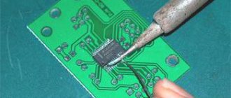
There is no need to explain how to use a breadboard for soldering: just insert the parts into the holes and solder them to each other and to the jumpers. But soldering should be done carefully, since frequent overheating causes the contact pads and traces to peel off from the board.
Use for assembling a jumper circuit with an alligator clip
If all we want to build is a simple circuit with one battery and one resistor, we can easily use alligator clip jumpers:
Figure 1 – Circuit with one battery and one resistor
Jumper wires with alligator clips on each end provide a safe and convenient method for electrically connecting components.
If we wanted to build a simple series circuit with one battery and three resistors, we could use the same point-to-point assembly technique using jumpers:
Figure 2 – One battery and three resistors
Which development board should I choose?
The easiest to use is a solderless board, which is why it is very popular today, and even novice radio amateurs know how to work with a solderless breadboard. In addition, the boards are durable and very reliable. Printed circuit boards are more difficult to work with because they require soldering, but they have the important advantage that they can be used to prototype the final installation on a permanent printed circuit board.
Therefore, it would be a good idea to have both types of breadboards and use them depending on the situation. Oh yes, and you can buy breadboards here.
From n/a Vladimir Vasiliev
PS Friends, be sure to subscribe to updates! By subscribing, you will receive new materials directly to your email! And by the way, everyone who signs up will receive a useful gift!
We supply power to the breadboard
There are different ways to supply power to the breadboard.
If you are working with Arduino, you can connect the 5V (3.3V) and Gnd pins to two different breadboard rails. The picture below shows the connection of the Gnd pin from the Arduino to the mini breadboard rail.
Typically, the Arduino is powered from a USB port on the computer or from an external power source, which we can supply to the breadboard rail.
Solderless circuit boards with pegs
It was already mentioned above that some circuit boards have pins for connecting an external power source.
To get started, you need to connect the pegs to the rails on the breadboard using conductors. The pegs are not connected to any one rail, which gives you some wiggle room as to which rail to supply power and ground to.
To connect the wire to the peg, unscrew the plastic cap and place the end of the wire into the hole (see photo below). After this, screw the cap back on.
Typically, you will need two pegs: one for power and one for ground. A third peg can be used if you need an alternative power source.
The pegs are connected to the rails, but that's not the end. Now you need to connect an external power source. There are several options.
You can use special jacks, as shown in the photo below.
You can use “crocodiles” and even ordinary conductors. Depends entirely on your preferences and the parts you have available.
One of the fairly universal options is to solder the contacts on the jack for your power source and connect the wires to the pegs, as shown below.
You can also use special power stabilizer modules, which are produced for solderless circuit boards. Some modules make it possible to power the breadboard from a USB port, some are made with standard jacks for power supplies. Most of these power stabilizer modules provide voltage regulation. For example, you can select the voltage that will go to the rail: 3.3 V or 5 V. One of the options for such voltage regulator/stabilizer modules is shown in the figure below.