Types of lifting devices
What the pulley for lifting loads and the construction crane have in common is the use of the idea of increasing force - the rule of leverage.
In order to balance the load on the short side of the lever, you need to apply less force to its long side to the extent that the short arm is less than the long one. The ratio of forces at the ends of the lever is called the gear ratio. You can balance and even lift a weight with an effort less than its weight, but the path made by the end of a long lever will be longer than that of a short one, just as less force was applied to lift it. There is no gain in work (F1*L1=F2*L2), but this is not required. The use of Archimedes' principle is implemented in different lifting mechanisms, and how depends on the purpose of the lift. Designs differ in gear ratio, principle of force transfer, mobility, strength, and energy used. The most popular types for self-production:
- chain hoists;
- drum structures;
- lever mechanism.
To choose the type of device needed for specific work, it is worth familiarizing yourself with their capabilities and limitations.
Pulley hoist. Purpose and device, types, diagram.
The crane drive has its limits. Or rather, the cost of the engine is growing much faster than the weight of the load it can lift. Of course, nothing prevents you from installing a very expensive engine, but there is a better way - using a chain hoist.
In fact, it was with the chain hoist that the development of hydraulic and mechanical engineering as complex mechanisms began. In its design, the pulley uses more ancient inventions, such as a block and a flexible joint. They did not immediately begin to use a rope instead of a lever.
Later, the chain hoist began to be used everywhere. Not a single sailing ship can do without such simple but irreplaceable rigging. Of course, the modern design of the pulley has changed greatly, but the essence remains the same.
The principle of operation of pulley hoists
The only simpler device for moving heavy objects is a metal scrap. The main element is a wheel with a chamfer in the middle of the outer surface, the axis of which is fixed to the ceiling beam. You can throw a hoist over it, and the lift with a gear ratio of 1 to 1 is ready. To increase the leverage, let's pass the hoist through another loose wheel, the axis of which is connected to the load, and fix the hoist at the top of the structure.
The transfer coefficient will become equal to 2 . Now let's attach another wheel to the ceiling, and pass the end of the hoist through it, securing it to the axis of the lower wheel. The gear ratio will become equal to 3. And so on, by adding one wheel at a time and changing the mounting location of the hoist, you can increase the gear ratio.
The location of the wheels relative to each other may be different.
The most compact designs are those with single-axle wheels. The design of such devices has two wheel holders. Having studied the drawings of the chain hoist, it will not be difficult to assemble it with your own hands. You will need two clips:
- traverse;
- carrying bracket;
- cheek for mounting parts;
- wheel (block);
- emphasis;
- bearing;
- sleeve;
- axis;
- axle holder;
- bearing oiler;
- hoist limiter;
- screw;
- bearing;
- cheek.
The end of the hoist is fixed to one of the clips.
Pulley hoists also have disadvantages. To increase the gear ratio by 1, you need to add one wheel each time, as a result the weight of the mechanism increases. In addition, bending the cable on each wheel requires force, reducing the efficiency of the device. You can reduce these losses by increasing the diameter of the wheels, but at the same time there will be an increase in the weight and dimensions of the pulley. Other types of lifts do not have these disadvantages.
Chain hoist diagram
Here is the simplest diagram of a chain hoist.
Circles are blocks. A large drive circle, or rather a drum, of a load-lifting crane. The end of the cable is not fixed to the crane hook, but to a surface that is stationary relative to the crane. Such a surface can be a crane boom or, if we talk about tower cranes, a carriage. The lower block is not fixed to the crane in any way and is movable relative to it. These are the two simplest schemes for constructing a chain hoist.
What loads arise in this case?
Calculation of the chain hoist
It would be more correct to ask how the load on the engine and on the rope itself will change. In our case, it will decrease by half. Of course, you can cite formulas and school examples known since the time of Archimedes, but you can take my word for it. But this is a relatively simple example. I will tell you how to calculate a more complex chain hoist in another article. Now let’s look at what types of chain hoists there are.
Manual drum winches
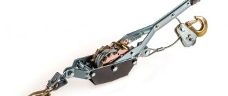
The principle of operation of winches resembles a simple lever fixed at a fulcrum. If the short arm of the lever is the surface of the cylinder, and the load is attached to it by a cable, you will get a winch with a gear ratio equal to the ratio of the length of the lever and the radius of the cylinder. To prevent reverse rotation, a ratcheting mechanism with a spring-loaded pawl is installed on the axis - a ratchet. You can assemble such a hand winch with your own hands according to the drawing:
However, the high gear ratio of the system will require a very long handle, which is inconvenient. The solution is found in two types of drum winches, which increase the gear ratio using gears or a worm gear.
How to make a winch with your own hands using a worm gear can be seen in the drawing:
A ratchet is not needed in this design; the gear ratio, when the worm flange passes over each gear tooth, is equal to the number of gear teeth multiplied by the ratio of the length of the handle to the radius of the worm. But a significant disadvantage will be the friction between the teeth and the comb. The mechanism requires constant lubrication.
A gearbox made of gears operates with much less friction. When using the principle of transmitting force through a pair of gears of different diameters, the easiest way to make a manual drum winch with your own hands is this:
Please note that a stopper is required in such devices. This design is used for small heights or lengths of cargo movement. A cable guide will help increase the movement distance by evenly distributing the cable along the length of the cylinder. The easiest way to get the result is to use a spring-loaded plate or rod that presses the cable to the drum:
How rope affects work efficiency
You can avoid pinching and twisting of the rope if you use additional devices, for example, mounting plates, which allow you to space the rollers relative to each other. We categorically do not recommend using stretchable ropes in pulley hoists, since in comparison with conventional static products they seriously lose in efficiency. When assembling a block for lifting loads, specialists use both load and separate ropes, which are attached to the object independently of the lifting device.
There is some advantage to using separate ropes. The idea is that a separate rope provides the ability to pre-assemble or pre-assemble the entire structure. In addition, the passage of knots can be significantly facilitated, since the entire length of the rope is used. The only drawback is the inability to secure the load automatically. Cargo ropes can boast of just this feature, so if there is a need to automatically secure a load, use a cargo rope.
The reverse motion is of great importance. This effect is inevitable, since at the moment of removal, as well as when intercepting the rope or stopping to rest, the load certainly moves in the opposite direction. How much the load goes back depends on the quality of the blocks used, as well as the entire device as a whole. This phenomenon can be prevented by purchasing special rollers that allow the rope to pass only in one direction.
Let's talk a little about how to properly attach a cargo rope to a lifting mechanism. Not always, even the most prudent master has a rope of the required length, which is required to attach the dynamic part of the block. Therefore, several methods of attaching the mechanism have been developed:
Using grasping knots. These knots are tied in five turns from cords, the cross-section of which does not exceed 8 mm. The use of such nodes is the most effective and, accordingly, widespread. According to experts, the units are very durable and reliable. Only a load over 13 kN can cause such a unit to slip
The important thing is that even when sliding, the knot does not deform the rope in any way, leaving it safe and sound. Application of general purpose clamps. These devices can be used even in difficult climatic conditions, for example, on wet or icy ropes
A load of 7 kN can cause the clamp to slip, which leads to damage to the rope, although not very severe. Personal clips. They are used only for small jobs, since a load over 4 kN leads to the clamp slipping and subsequent rope breakage.
Simplifying device assembly
At home, you can use improvised materials and ready-made transfer units. For example, the ratchet used in a KAMAZ vehicle to equalize the braking force is a ready-made worm gear mechanism.
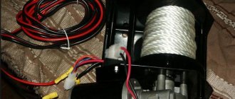
You can get rid of manual lifting for a long time if you assemble the motorized winch system with your own hands for work once. To do this, you need to put a gear on the winch drive axis, connecting it with a chain to the chainsaw drive sprocket on a rigid housing structure.
By combining block mechanisms with drum winches, you can work to compensate for the shortcomings of each type of lift. For example, pulley hoists do not provide a lock that prevents reverse movement of the hoist, but drum swans eliminate this very simply. But the angle between the lifting force vector and the weight vector of the pulley can be almost anything, which winches cannot boast of.
You can use purchased lifts on the farm, but, as a rule, winches are needed where stores are far away - and always urgently. It's worth looking in the garage for some parts to get out of the situation.
We make a chain hoist from paper cups and gears
The devices used in construction are very complex, which is logical, because it requires lifting large loads to a fairly large height. Understanding their design features can be very problematic. The same cannot be said about household chain hoists that are used in everyday life. They are so simple and understandable that anyone can build a chain hoist with their own hands. For this we need the following devices:
- several paper glasses;
- scissors;
- lace or strong thread acting as a rope;
- plasticine;
- plastic hangers.
First of all, you will need to make a basket in which the cargo will move. For these purposes we will use paper cups through which we thread a rope. We assemble the chain hoist from hangers. We fix the rope or thread on the top of the hanger, and then wind it around the crossbar several times. The basket obtained from the glasses should be hung on the lower hanger by the hook. In principle, at this point the collection of the chain hoist can be considered complete. To lift loads, you just need to use the mechanism correctly. To do this, you will need to pull the free end of the thread, which will lead to the connection of the hangers. Now you can try to lift heavy objects to a height.
There is another way to make a chain hoist with your own hands, which is somewhat more complicated, but is more efficient and reliable in design. Here we need bearings, a gear, a hook, cables with blocks, and a threaded rod. First, we attach the bearings to the stud, after which we install the gear on the end of the stud to make it more convenient and easier to use a homemade pulley. All that remains is to throw the cable over the gears and secure it; the free end will be equipped with a hook, which is necessary for lifting objects.
Finally, let us remind you that when working with any chain hoists, purchased in a store or made at home, you should definitely remember safety precautions. It is necessary to carefully check the structure for strength and integrity
The loads themselves should be lifted smoothly and carefully, without being located under a suspended object at this time
Lifting loads without special equipment - how to calculate and make a chain hoist with your own hands
Lifting machines are designed to help a person lift something heavy to a height. Most lifting mechanisms are based on a simple block system - a pulley system. It was known to Archimedes, but now many people do not know about this brilliant invention. Remembering your physics course, find out how such a mechanism works, its structure and scope. Having understood the classification, you can begin to calculate. For everything to work out, here are instructions for constructing a simple model.
Block system - theory
The invention of the chain hoist gave a huge impetus to the development of civilizations. The block system helped build huge structures, many of which have survived to this day and puzzle modern builders. Shipbuilding also improved, and people were able to travel great distances. It's time to figure out what it is - a chain hoist and find out where it can be used today.
Structure of the lifting mechanism
A classic chain hoist is a mechanism that consists of two main elements: a pulley; flexible connection
A pulley is a metal wheel that has a special groove for a cable along its outer edge. An ordinary cable or rope can be used as a flexible connection. If the load is heavy enough, ropes made of synthetic fibers or steel ropes and even chains are used. To ensure that the pulley rotates easily, without jumping or jamming, roller bearings are used. All elements that move are lubricated.
One pulley is called a block. A pulley block is a system of blocks for lifting loads. The blocks in the lifting mechanism can be stationary (rigidly fixed) and movable (when the axis changes position during operation). One part of the pulley is attached to a fixed support, the other to the load. Movable rollers are located on the load side.
Gearbox selection
The next problem is the choice of gearbox. Any 220 V electric winch with your own hands must contain a mechanism that will transmit rotation with a large traction force. There are the following types of gearboxes:
- Worm drives transmit rotation at an angle of 90 degrees and do not require braking devices, as they have good self-braking properties.
- They are not used for winches due to the complexity of the perpendicular arrangement of the main drive and secondary shafts.
- Cylindrical, are one or more pairs of gears in one plane, meshed. Rotation is transferred from the smaller wheel to the larger one. They have high reliability, but less tractive effort. Convenient for use when constructing homemade winches.
Planetary gearbox, the most common at the moment. It usually consists of 3 satellites, a sun gear, a ring gear and a carrier. They have an increased working life and transmitted power, but are complex in design.
The simplest solution when manufacturing a unit, an electric winch for 220 V, of course, you can always use a converter, especially since ready-made high-power devices are available for sale. An asynchronous motor can be used as a drive motor, but it is better to use a motor from a washing machine. Modern models are quite powerful and productive.
DIY mini-crane: overview of options
When building a house from aerated concrete, timber, brick, etc. There is often a need to lift a load. For example, you need to “throw” blocks or wooden beams onto the second floor, lift bags of cement, or pour an armored belt. Doing this manually, even with the help of assistants, is not so easy - health is more expensive. Hiring a truck crane or manipulator for a small amount of work is expensive. The solution is to use a mini-crane, which, to reduce the cost of construction, is made by hand.
- How to make a lift for laying aerated concrete.
- What parts and tools are needed to build a mini crane.
- How to reduce the costs of building a universal lift.
Lift for laying aerated concrete blocks
Abroad, during the construction of private houses, cranes and various lifts are often used. This way construction goes faster, which means the “box” is cheaper, because It is more profitable to use small-scale mechanization tools than to hire laborers. Our developer relies on himself and often builds a house “with one helmet.” Therefore, the urgent question is how not to physically overstrain yourself when laying a wall from aerated concrete blocks weighing 35-40 kg.
An interesting option is the unusual homemade “assistant” of the FORUMHOUSE user with the nickname Krestik. First, let's show what he took as a basis.
German mini crane with retractable central post
A special feature of the lift is the original folding “arm-boom”, with the help of which the crane, moving on wheels, can reach two opposite walls.
I am building a house myself and, in order to be able to lay aerated concrete blocks, I built a lift according to the above model. The crane was made completely collapsible, except for the base. I didn’t measure the maximum load on the hook, but it easily lifts me (weighing 95 kg).
Technical characteristics of the lift:
- width – 2200 mm;
- height – 4200 mm;
- boom radius – 4200 mm;
- load capacity of electric hoist – up to 800 kg;
- total weight of the crane with ballast is approximately 650 kg;
- lift weight without ballast – about 300 kg;
- The maximum lifting height of the masonry block is 3500 mm.
The working height of lifting blocks is adjustable in two ranges. The first is 1750 mm. The second is 3.5 m, for which the structure is raised, sliding upward along the supporting “legs” using a hydraulic jack lined with spacers made of GB blocks.
To make the lift, the user needed:
- swivel wheels;
- profile pipes for the mast, “legs” and boom with a section of 12x12 cm, 12x6 cm, wall 6 mm;
- pipe-jibs – 63x3 mm;
- powerful gate hinges;
- The boom rotating mechanism is made of ST45 steel and “205” bearings.
During operation, the design was modified. For example, the user laid the cable for the winch in a corrugated pipe and extended the cable for the control panel.
The design has a number of shortcomings that I would like to correct. For example, I’m thinking about making wireless control, replacing the gate hinges with bearings. Increase the number of “joints” in the boom at the same reach. Instead of a temporary counterweight - bags of sand concrete, pour concrete ballast.
Important nuance : in order for the lift to move around a construction site or, for example, on a concrete floor slab on the second floor, you need to keep the workplace clean, because GB fragments and debris interfere with the relocation of the tap.
Refilling chain hoists
Reeving is a procedure for changing the location of pulleys and the distance between them. The purpose of this operation is to regulate the speed and height of lifting loads in accordance with a certain pattern of cable passage through the blocks of the lifting mechanism. There are the following types of reserve:
- One-time. 1 rope is attached to the hook, which is passed through all the fixed blocks and wound onto the drum.
- Double. The first end of the rope is attached to the head of the crane's rotating element, the second - to the winch. This reeving method can be used on jib-type cranes.
- Quadruple. 2 working branches of the cable are routed through the working boom pulleys. Adjacent pulleys are fastened together using a static block installed on the platform stand. This reeving method is used for heavy-duty applications.
There is also variable reeving. It can be either double or quadruple. The movable rollers are mounted on several movable cages held by a rope. The reeving ratio is changed by lowering the hook suspension onto the support while reeling in the rope.
Mini crane made from scrap metal
Another version of a lifting mechanism made of metal “lying underfoot” was made by a portal participant with the nickname Petr_1.
According to Peter_1, the reason for the construction of the crane is that the house is getting higher and higher, and the blocks and concrete are getting heavier. Therefore, after revising the “unnecessary things”, the user manufactured a completely dismountable crane with a lifting capacity of 200 kg.
I think my crane can lift more, but I didn’t overload it. The crane can be disassembled into parts weighing 30-60 kg and can be easily transported in a car trailer. I carry an arrow on the trunk. Statically tested a structure weighing 400 kg. I usually lift up to 150 kg. This is quite enough for my construction needs.
The design of the crane is a hodgepodge of what was at hand. Let's list the main details:
- swivel unit - truck hub;
- the boom is made of a pipe with a diameter of 75 mm;
- outriggers and base - a rectangular pipe with a section of 8x5 and 8.5x5.5 cm;
- the base of the tower is the “200th” channel;
- worm gearboxes for boom and cargo winches.
- three-phase electric motor with reverse, power 0.9 kW, converted to power from a 220 V network;
The crane turned out to be mobile, and by lowering the boom, it can be moved from place to place, rolling on wheels along compacted soil. Level adjustment is carried out using screw supports.
Metal, gearboxes and rollers were purchased at a recycled metal shop. Only the cable and bearings are new.
The weight of the crane without counterweight is about 250 kg. The cost of the structure, taking into account the purchase of consumables - cutting discs for angle grinders, electrodes for a welding inverter and paint, is 4 thousand rubles.
Crane, + time for turning, + selection of components and fitting of components, I completed it in 3 working days. In the future, after finishing the work, I will completely disassemble it.
Powerful block without DIY turning work
Hello, Today, with my own hands - a powerful block without the use of turning.
It was necessary to change the design of the suspension in greenhouses, where I used a block system to tension the 3 mm cable while bending it at 90°, so several blocks were needed.
Surely there are others, but for sale I found only one like the one in the photo, which didn’t quite inspire confidence in me, looks beautiful, but is completely unsatisfactory in terms of functionality, namely reliability, plus the price (8 pieces were needed).
I had to make my own version, and without the use of turning work, which I present to your attention.
The block described in this publication is designed for a cable Ø 3 - 4 mm and for the radius of its bend that I need, but using the same principle it is possible to make a block for a different cable diameter and maximum load, which will depend only on the choice of the rigging eyelet.
Of course, it is not designed for high rotation speeds, but for work in conditions where this is not required, it is quite suitable, the main thing is its power, and therefore reliability.
And if you make a pulley on a lathe, then the block will meet absolutely all the requirements necessary for it.
Components for making the block:
Earring (bracket) rigging 5 mm - 1 pc. The Omega type configuration is better, but I only found a straight one of this size.
Reinforced washer M8 - 2 pcs.
M8 washer - 2 pcs. Attention! They should be the same, given that the washers come in different diameters and thicknesses. I selected washers with a total thickness of 4 mm, which is what I needed
I selected washers with a total thickness of 4 mm, which is what I needed.
Screw M8 × 25 — 1 pc. Attention! For convenience, when drilling an axial hole, it is advisable to choose the screw shown in the photo. Through nut M8 - 1 pc.
Through nut M8 - 1 pc.
Manufacturing:
Making several blocks at once takes very little time if you perform each individual operation for all the workpieces at once.
Assemble the prepared components together.
To do this, hold the screw head in a vice and tighten the nut tightly.
Clamp the workpiece with the threaded part in the drill chuck using a Ø 4.8 mm drill. make an axial hole.
It is not necessary to drill the entire length of the screw, but only to the required size.
Using a grinder and a cutting wheel 1 mm thick, cut off the screw head and nut to a thickness of 1.5 ÷ 2 mm from the plane of the outer washers.
Attention! This option for manufacturing a block provides for the possibility of not using a welding machine, but it would be better if, before or after cutting, electric welding (two or three points) is used to attach the screw head and nut to the outermost wide washers. Using a suitable tool, with a diameter slightly larger than the thickness of the manufactured pulley, slightly spread the “horns” of the earring (I used a Ø 12 mm drill as a tool)
Using a suitable tool, with a diameter slightly larger than the thickness of the manufactured pulley, slightly spread the “horns” of the earring (I used a Ø 12 mm drill as a tool).
Using light blows of a hammer, with the device inserted, bring the “horns” of the earring together to the desired size, thus fitting the rigging bracket to the manufactured pulley.
Place the pulley in place.
Attention! Everything is manufactured without turning, so adjustments are indispensable for free rotation of the pulley. Powerful block for cable 3 ÷ 4 mm, made without turning, ready
A powerful block for a cable 3 ÷ 4 mm, made without turning, is ready.
That's all. Good luck!
Become the author of the site, publish your own articles, descriptions of homemade products and pay for the text. Read more here.
Inexpensive mini lift
Practice shows that when building a private house, a real crane is not always needed. Often, a developer can get by with “little expense” and make a small lift based on an electrically driven hoist.
My design is simpler than the authors above, but it suits me quite well. I bought a hoist with a load capacity of 300 kg without a block and 600 kg with a block. Tests have shown that the device can lift a load weighing 250-270 kg, then the engine protection is triggered. During the construction season, I used it to lift about 40 pallets with building blocks, a 6-meter beam for the mauerlat, rafters, mortar for masonry and concrete for the reinforced belt.
The lift, again to save money, is made from used pipes, angles and channels.
All rust was cleaned off with a grinder, and the pipes were sprayed and then painted with paint with a rust reducer.
In order to be able to assemble the lift on the ceiling of the second floor, all components (where welding is not needed) are made dismountable - with bolted connections.
A hoist is installed on the stand using clamps.
In case of rain, a plastic bottle with the bottom cut off is placed on the control panel.
The telpher covers a canopy made of used roofing iron.
When lifting a pallet, two boards are placed under it, and the pallet is lowered onto them.
The entire structure is fixed to the floor with clamps.
Drawing with dimensions of the lift.
These are topics that describe in detail how to make a lift for aerated concrete, and provide dozens of options for mini-cranes, from simple to the most complex designs.
Multiplicity of chain hoist
Let's complicate the scheme. No one is stopping us from using not two blocks, but three, four or more.
The figure shows a double chain hoist. The load on the engine is reduced by approximately four times. “Approximately” because we lose part of the effort due to friction between the rope and the block. The unit efficiency is usually 0.97.
The multiplicity of the pulley is precisely the ratio of the forces of the cable on the drum and near the load. In the example above, the multiplicity of the pulley is four.
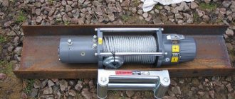
Types of winches
Those who have ever lifted a bucket of water from a well are already familiar with the principle of the winch. This device is designed for tasks such as lifting or moving loads. Its design includes a drum or pulley for a cargo rope, a drive mechanism with intermediate gears, a braking device and a support frame. According to their purpose, winches are divided into traction type (for moving loads in a horizontal plane) and lifting type.
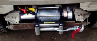
Winches are used for many purposes - this can be mooring ships, lifting anchors, or consisting of a large number of winch machines. A manual winch, assembled with your own hands, will be a convenient solution in the construction of a country house.
Block system
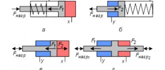
The use of a movable block gives a double gain in force, the use of a stationary block allows you to change the direction of the applied force.
In practice, combinations of movable and fixed blocks are used. Moreover, each moving block allows you to halve the applied force or double the speed of moving the load. Fixed blocks are used to connect movable blocks into a single system. Such a system of movable and fixed blocks is called a pulley block. A chain hoist is used in cases where it is necessary to lift or move a heavy load with minimal effort, provide tension, etc. The simplest pulley system consists of just one block and a rope, and at the same time it allows you to halve the traction force required to lift a load.
Figure 1. Each moving block in the pulley gives a double gain in strength or speed
Typically, lifting mechanisms use power pulleys to reduce the tension of the rope, the moment from the weight of the load on the drum and the gear ratio of the mechanism (hoist, winch). High-speed pulleys, which make it possible to obtain a gain in the speed of movement of the load at low speeds of the drive element, are used much less frequently. They are used in hydraulic or pneumatic lifts, loaders, and telescopic boom extension mechanisms of cranes.
The main characteristic of the pulley is the multiplicity. This is the ratio of the number of branches of the flexible body on which the load is suspended to the number of branches wound on the drum (for power pulleys), or the ratio of the speed of the leading end of the flexible body to the driven end (for high-speed pulleys). Relatively speaking, the multiplicity is a theoretically calculated coefficient of gain in strength or speed when using a chain hoist. Changing the multiplicity of the pulley system occurs by introducing or removing additional blocks from the system, while the end of the rope with an even multiplicity is attached to a fixed structural element, and with an odd multiplicity - on the hook clip.
Figure 2. Rope fastening with even and odd multiplicity of pulley system
The gain in force when using a pulley with $n$ movable and $n$ fixed blocks is determined by the formula: $P=2Fn$, where $P$ is the weight of the load, $F$ is the force applied at the input of the pulley, $n$ - number of moving blocks.
Depending on the number of rope branches attached to the drum of the lifting mechanism, single (simple) and double chain hoists can be distinguished. In single pulley hoists, when winding or winding up a flexible element due to its movement along the axis of the drum, an undesirable change in the load on the drum supports is created. Also, if there are no free blocks in the system (the rope from the hook suspension block directly passes to the drum), the load moves not only in the vertical, but also in the horizontal plane.
Figure 3. Single and double pulleys
To ensure strictly vertical lifting of the load, double pulleys (consisting of two single ones) are used; in this case, both ends of the rope are fixed to the drum. To ensure the normal position of the hook suspension in case of uneven stretching of the flexible element of both pulleys, a balancer or equalizing blocks are used.
Figure 4. Methods to ensure vertical lifting of the load
High-speed pulleys differ from power pulleys in that in them the working force, usually developed by a hydraulic or pneumatic cylinder, is applied to a movable cage, and the load is suspended from the free end of a rope or chain. The gain in speed when using such a pulley is obtained as a result of increasing the height of the load.
When using pulleys, it should be taken into account that the elements used in the system are not absolutely flexible bodies, but have a certain rigidity, so the oncoming branch does not immediately fall into the stream of the block, and the running branch does not straighten out immediately. This is most noticeable when using steel ropes.
Question: why do construction cranes have a hook that carries the load, not attached to the end of the cable, but to the holder of the moving block?
Answer: to ensure vertical lifting of the load.
referencenick.ru
Manual winch drawings
The design drawings of this manual winch are of an overview nature, since the size of the worm gear depends on the geometry of the shaft used, as well as the worm gear.
The structure consists of the following elements:
• worm gears; • cable winding shaft; • brass bushing; • housings; • pens.
Worm gears
This part must be selected taking into account the rated load capacity of the winch. Based on the dimensions and the proposed diagram, we can make a simple mechanism for lifting the load.
Cable winding shaft
It can be a solid structure, or welded from several elements.
Brass bushing
Due to the brass bushing, the shaft slides when rotating. This design option is suitable for temporary work. For continuous use of the mechanism, we use rolling bearings instead of bushings. Due to this, the design will become more complex and at the same time more expensive. If necessary, as the bushings wear out, they can be replaced. This will be a cheaper solution.
Frame
For manufacturing, we take a bent steel unequal-flange channel GOST 8281-80 and sheet metal GOST 19903-74. In our case, the body is made of channel 200x50x30x4 mm and sheet metal 4 mm thick. The body uses a long and short channel, which are fastened using a left and right plate, and an M8 bolt connection.
Pen
To make the handle, a metal fragment and a wooden insert were used. To fasten the handle to the shaft, a 10x36 GOST 3128-70 pin is used.
How do blocks work?
The block consists of one or more wheels (rollers) encircled by a chain, belt or cable. Just like a lever, a pulley reduces the force required to lift a load, but it can also change the direction of the force applied.
The gain in strength comes at the cost of distance: the less effort required to lift a load, the longer the distance that the point of application of this effort must travel. The pulley system increases the strength gain by using more load-carrying chains. Such power-saving devices have a very wide range of applications - from moving massive steel beams to the height of construction sites to raising flags.
As with other simple mechanisms, the inventors of the block are unknown. Although blocks may have existed before, the first mention of them in literature dates back to the fifth century BC and relates to the use of blocks by the ancient Greeks on ships and in theaters.
Moving pulley systems mounted on a suspended rail (picture above) are widely used on assembly lines because they greatly facilitate the movement of heavy parts. The applied force (F) is equal to the weight of the load (W) divided by the number of chains used to support it (n).
Single fixed blocks
This simplest type of pulley does not reduce the force required to lift the load, but it does change the direction of the force applied, as shown in the figures above and above right. A fixed block on the top of the flagpole makes it easier to lift the flag by allowing the cord to which the flag is attached to be pulled down.
Single moving blocks
The single pulley, which can be moved, reduces the force required to lift the load by half. However, halving the applied force means that the point of application must travel twice as far. In this case, the force is equal to half the weight (F=1/2W).
Block systems
When using a combination of a fixed block and a moving one, the applied force is a multiple of the total number of load-carrying chains. In this case, the force is equal to half the weight (F=1/2W).
A weight suspended vertically through the block allows horizontal electrical wires to be pulled taut.
The overhead lift (picture above) consists of a chain wrapped around one movable and two fixed blocks. Lifting a load requires a force that is only half of its weight.
A pulley, commonly used in large cranes (picture at right), consists of a set of moving pulleys from which a load is suspended, and a set of fixed pulleys attached to the crane's boom. By gaining strength from so many blocks, the crane can lift very heavy loads, such as steel beams. In this case, the force (F) is equal to the quotient of the weight of the load (W) divided by the number of supporting cables (n).
information-technology.ru