Pistons are used:
In internal combustion engines
The movement of the piston along the cylindrical plane of the cylinder, through the crank mechanism, rotates the engine crankshaft, which transmits torque.
In compressor installations
In compressors, the crankshaft is set to rotate by an electric motor and the shaft, through a crank mechanism, moves the piston along the cylindrical plane of the cylinder, which compresses the gas.
The design of the piston can be divided into several components:
Bottom
performed in various forms.
The sealing part
of the piston design serves to create compression.
Rings (compression, oil scraper) are installed on it. The skirt
is the guiding part of the piston, where there are casting bosses for installing the piston pin.
In pneumatic cylinders
Provides reciprocating movement of the rod under the action of compressed air.
In hydraulic cylinders
Provides reciprocating movement of the rod under the influence of hydrostatic pressure of the liquid.
Requirements for piston designs.
- Structural strength.
- Light weight.
- Temperature loads (material stability) (engines, compressors).
- Reduced noise characteristics.
- High wear resistance.
- High cyclicality.
- Ecology (minimal emissions of harmful substances into the atmosphere).
- Low thermal conductivity (engines, compressors).
Source
Hydraulic piston
An integral part of any hydraulic system is the hydraulic piston. It is made in the shape of a cylinder. The activity of the piston consists of performing reciprocating movements in a special sleeve. The main function of a hydraulic piston is to convert mechanical energy into fluid pressure energy and vice versa.
Pistons come in either one-piece construction or consisting of several components. It may include parts such as a rod, sealing and guide rings. The scope of application is quite extensive; they are used in various hydraulic cylinders and pumps.
The main function of the piston is to regulate the volume as well as the pressure in the piston chamber.
Our production
- Manufacturing of hydraulic cylinders of any complexity for special, municipal and agricultural equipment, both domestic and imported. In production we use components made in Italy, which ensures long and uninterrupted operation of the hydraulic unit.
- Sale of new hydraulic cylinders and various hydraulic units.
We are registered on all government platforms as well as on the supplier portal, where you can enter into an agreement with us for the repair and maintenance of special equipment.
We produce our own hydraulic cylinders, and we are also the official representative of leading manufacturing plants in Russia, Austria, Italy
The products of our company are distinguished by their high quality, reliability and significant service life. All products are guaranteed and provided with warranty service. We will be glad to see you among our clients. Write to us or call us and we will try to solve your problems as soon as possible.
Hydraulic piston device
There are two characteristically different types of pistons:
- The surface of the mechanism is sliding and is in direct contact with the surface of the sleeve. Such devices are made from antifriction substances brass, fluoroplastic and bronze.
- The most popular types are pistons in which special guides and sealing rings slide along the liner. In the body of such a device, special grooves are made for these rings. The mechanism in this case is made of steel.
To combat leaks in the cylinder, rings and cuffs are used. If there is simultaneously high pressure on the rod side and on the piston cavity side, 2 sealing rings or cuffs are installed, working in different directions. If it is on one side, then usually only one cuff is placed.
Working principle of hydraulic piston
There are two main fundamentally different types of work:
- In a hydraulic cylinder. The working fluid enters the cavity of the hydraulic cylinder and exerts pressure with a certain force on the piston. As a result, it moves in the direction required for the hydraulic system, and performs the function of converting hydraulic energy into mechanical energy. Special seals prevent fluid from flowing from the piston chamber into the rod chamber at high pressure.
- In the hydraulic pump. Here first we make mechanical movements. As a result of which we put pressure on the working fluid using mechanical energy, the working chamber decreases and the fluid goes into the injection system. Next, we make a reverse movement as a result of which the working chamber increases, and liquid is sucked through the supply system.
Types of hydraulic cylinders
Depending on the design, there are several types of hydraulic cylinders.
- By the nature of the move
- Single stage
- Telescopic
- In the direction of action of the working fluid
- Single acting
- Double acting
- If possible, braking
- With braking
- No braking
- By type of worker
- Plunger
- Membrane
- Bellows
- Piston With one-way rod
- With double-sided rod
Double-acting hydraulic cylinder design
Double-acting hydraulic cylinders have two separated sealed working cavities into which liquid is supplied through different pipelines. Double-acting hydraulic cylinders can transmit the developed force in both forward and reverse directions.
Let's consider the design of a double-acting hydraulic cylinder using the example of the most common design with a one-sided rod.
Hydraulic cylinder with one-way rod
The main structural elements of a double-sided hydraulic cylinder with a one-sided rod are shown in the figure.
- stock
- front cover
- sleeve
- piston
- screw
- back cover
- wiper
- rod cuff
- rod guide ring
- piston cuff
- rubber ring
- piston guide ring
Operating principle of hydraulic cylinder
The working fluid from the pump is directed through the distributor into one of the cavities (piston or rod), the opposite cavity is connected to the drain.
When fluid enters the piston cavity, the hydraulic cylinder rod extends, if necessary, overcoming the load force. When working fluid enters the rod cavity, the hydraulic cylinder rod is retracted.
| Extend the stem | Neutral position | Retract the rod |
When fluid enters the piston cavity, the force developed by the hydraulic cylinder can be calculated using the formula:
When liquid enters the rod cavity, the effective area will change; the rod area must be subtracted from the piston area.
The tightness of the working chambers is ensured by lip seals, which do not allow fluid to flow from the piston cavity to the rod cavity. A cuff is also installed in the hydraulic cylinder cover to seal the rod, and a wiper to prevent contamination particles from entering the cylinder cavity.
Hydraulic cylinder with double-sided rod
The force and speed of movement of the piston with the rod during forward and reverse stroke will be different. If the same forces are required or the same speed of movement of the output links, then hydraulic cylinders with a double-sided rod are used.
In this type of hydraulic cylinder, one piston is connected to two rods.
To calculate the speed and force of a hydraulic cylinder with a double-sided rod, you can use the formulas:
In modern technology, hydraulic cylinder designs with a double-sided rod with a fixed cylinder and a fixed rod are used.
Hydraulic cylinder - diagrams, calculations, drawing, device, principle of operation, disassembly, assembly
A hydraulic cylinder is a volumetric hydraulic motor with a reciprocating movement of the output link. Hydraulic cylinders are widely used as actuators of various hydraulic machines. Hydraulic cylinders are very diverse in design and principle of operation and are classified in accordance with GOST 17752-81.
Hydraulic cylinder force calculation
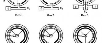
According to the direction of action of the working fluid, all hydraulic cylinders are divided into two groups: single-acting and double-acting. The liquid can exert pressure on the working body of a single-acting hydraulic cylinder only from one side, as in the diagrams in Fig. 1, a, d, d.
In these cylinders, the movement of the piston in one direction is ensured by the liquid supplied into the cavity, and the reverse movement is achieved in another way - due to a spring (see Fig. 1, a) or the weight of the load during vertical movement of the piston (see Fig. 1, a). d). The movement of the working body of a double-acting hydraulic cylinder in both directions is ensured by the working fluid (Fig. 1, b, c). In such hydraulic cylinders, fluid is supplied to both the left and right cavity.
Hydraulic cylinders are also divided according to the design of the working body. The most widespread are hydraulic cylinders with a working body in the form of a piston or plunger, and piston hydraulic cylinders can be made with a one-sided (see Fig. 1, i, b) or double-sided rod (see Fig. 1, c), and plunger hydraulic cylinders can be only single-acting and with a single-sided rod (see Fig. 1, d).
According to the nature of the stroke of the output link, hydraulic cylinders are divided into single-stage and telescopic (multistage). Single-stage hydraulic cylinders are shown in Fig. 1, a–d. Telescopic hydraulic cylinders consist of several pistons inserted into each other. As an example in Fig. 1, d shows a diagram of a two-stage telescopic single-acting hydraulic cylinder. In such a hydraulic cylinder, the pistons extend sequentially one after another.
The overall efficiency of hydraulic cylinders is determined primarily by the mechanical efficiency, which for most designs is 0.85...0.95. There are practically no hydraulic losses in the cylinders, and the hydraulic efficiency is (ηg = 1). Volume losses in the devices under consideration may occur in the gap between the piston and the cylinder. However, when this place is sealed with rubber rings or cuffs, they are small. Then the volumetric efficiency can also be considered equal to unity (η0 = 1).
When calculating the pressure drop across a hydraulic cylinder, two basic formulas are used. Let's consider them using the example of a double-acting hydraulic cylinder with a single-sided rod (Fig. 2). The first of them connects the force F on the rod and the pressure drop on the hydraulic cylinder (ΔP = P1 - P2). Simplified, it looks like this:
F= ΔP*S*ηm
where S is the effective area affected by the supplied pressure.
When the fluid moves from left to right in the calculation diagram (see Fig. 2.), this area is the area of the piston (S = Sp), and when moving in the opposite direction, it is the area of the piston minus the area of the rod (S = Sp-Ssh).
The second formula relates flow rate and piston speed:
Q=Vп*Sp*1/η0
or
Q´= Vп*(Sp-Sш)*1/η0
The formula is written in two versions, since the costs before and after the hydraulic cylinder are different. To explain this, let’s imagine that the piston in the calculation diagram (see Fig. 2.) has moved from the initial position to the right by a distance ( L ). In this case, a volume of liquid entered the left cavity of the hydraulic cylinder (W= Sp*L), and a smaller volume was displaced from the right cavity (W´= (Sp-Sш)*L). From the ratio of the volumes W and W´ it follows that the flow rates before and after the hydraulic cylinder are connected by the relationship Q / Q´ = Sp / (Sp-Ssh) For a hydraulic cylinder with a double-sided rod (see Fig. 1, c) Q = Q´.
Manufacturing of hydraulic cylinders according to drawings
Design of single-acting hydraulic cylinders
Single-acting hydraulic cylinders are capable of developing force in only one direction. The reverse stroke of such cylinders is carried out under the action of a spring, gravity, or external influence on the rod.
Plunger hydraulic cylinder
In hydraulic cylinders of this type, the liquid acts on a plunger located in the working chamber. The reverse stroke is carried out due to external forces or gravity.
The plunger is capable of transmitting only compression force; the magnitude of the force can be calculated using the relationship:
The speed of movement of the plunger will depend on the diameter of the plunger and the flow rate of the working fluid.
Spring return hydraulic cylinder
A spring return hydraulic cylinder is shown in the figure.
When the working fluid enters the piston cavity, a working stroke is carried out, the spring located in the rod cavity is compressed - the rod extends.
The reverse stroke is carried out due to the force of the spring, while the piston cavity is connected to the drain. The spring can be installed in both the piston and rod chambers.
Design features and principle of operation
The design of any hydraulic cylinder includes the following elements:
- body-sleeve;
- piston;
- piston rod
Plunger hydraulic cylinders are somewhat different in design, in which the plunger simultaneously performs the functions of a piston and a rod.
Hydraulic cylinder diagram
The operating principle of any type of hydraulic cylinder is based on the pressure of the working fluid on the piston. As a result of the impact on the hydraulic cylinder piston, the rod begins to perform cyclic work, transmitting force to the working unit of the equipment served by the device. Such a working unit, the functioning of which is ensured by a hydraulic cylinder, depending on the type and purpose of the equipment, can be a compacting platform, a bending or pressing mechanism, as well as a device of any other type that ensures the transmission of the force of the hydraulic cylinder to the final recipient of power energy.
Sliding hydraulic cylinder device
Since the force created by a hydraulic cylinder, as mentioned above, is formed due to the pressure exerted by the working fluid on the piston, the properties of this fluid have a significant impact on the efficiency of use, technical and operational characteristics of the cylinder itself. As a working fluid for piston or plunger type hydraulic cylinders, as a rule, a special oil is used, which must meet certain requirements for a number of parameters:
- chemical composition and density;
- temperature values at which the working fluid retains its original characteristics;
- the tendency of the working fluid to develop oxidative processes.
To operate hydraulic cylinders of various types and models, working fluid is pumped into their internal chamber using a manual or electric pump.
Hydraulic cylinders of special design
Let's look at several special designs of hydraulic cylinders.
Telescopic hydraulic cylinders
In telescopic hydraulic cylinders, one rod is placed in the cavity of another rod. This makes it possible to obtain a large amount of movement of the output link with unchanged dimensions, since in telescopic cylinders the stroke can exceed the length of the sleeve.
Single-acting telescopic hydraulic cylinder
The working fluid is supplied to the cylinder cavity through the rear cover. The sections are pulled out sequentially - first, the section with the largest effective area will begin to move, then the one with the smaller one. The speed when extending each subsequent section will increase, and the force will decrease, due to a decrease in the effective area. For this reason, the force on the section with the minimum effective area should be calculated.
The reverse stroke is carried out under the influence of external forces, while the working cavity is connected to the drain.
Double-acting telescopic hydraulic cylinder
The supply of working fluid in the design shown in the figure is carried out through the rod.
The sections are extended in the same order as in single-acting telescopic hydraulic cylinders.
The return stroke is ensured by the supply of working fluid to the rod cavity, while the piston cavity is connected to the drain.
Combined hydraulic cylinders
To increase the force on the hydraulic cylinder rod, in the absence of the possibility of increasing the outer diameter, tandem or sequentially installed hydraulic cylinders are used. The diagram of a double hydraulic cylinder is shown in the figure.
In this case, an increase in force is achieved by adding a second working chamber and an additional piston, which allows the effective area of the hydraulic cylinder to be increased.
Constructor for machine builders. Piston hydraulic cylinders
A. Shekunov, JSC "HydroPack Power Systems", V. Vasilchenko, Ph.D. tech. sciences
Hydraulic cylinders are widely used in hydraulic systems as sources of drive for the working parts of mobile machines and actuators of industrial equipment. In a hydraulic system with one, less often, two pumps, up to 6...10 hydraulic cylinders can be installed, and in some cases two or even three times more. According to their functional characteristics, hydraulic cylinders are volumetric hydraulic motors designed to convert the energy of the working fluid flow (WF) into the mechanical energy of the output link with reciprocating motion. Moreover, both the rod and the body (sleeve) of the hydraulic cylinder can act as a moving link.
Depending on the working cycle, required speeds and forces, piston hydraulic cylinders of different sizes and designs are used. For example, they can be single-acting or double-acting. In double-acting hydraulic cylinders, forward and reverse strokes are performed under the pressure of the fluid, and in single-acting hydraulic cylinders, the reverse stroke is performed under the action of an external load or spring.
To drive the working parts of mobile machines, double-acting piston hydraulic cylinders with a one-way rod exit are most widely used. The force on the rod and its movement can be directed in both directions, depending on which of the cavities the RJ is injected into; Usually the opposite cavity is connected to the drain hydraulic line. Hydraulic cylinders with a double-sided rod are used mainly for turning the working equipment of mounted excavators, with the housing being the moving link.
Double-acting piston hydraulic cylinders of a unified design are designed for hydraulic drives of mobile machines and are used in liquid fluid with a viscosity of 10 to 3500 mm2/s in temperate (U), cold (CL) and tropical (T) climates. In Russia, hydraulic cylinders must comply with general technical requirements in accordance with GOST 126514–87, GOST 17411–91. Below are their main parameters.
• Pressure: nominal Pnom, maximum Pmax and idle Pxx.
• Main dimensions: cylinder (piston) diameter D, rod diameter d, rod stroke L and working area ratio j.
• Nominal cylinder force Fnom, pushing force Fp, pulling force Fsh.
• Cylinder rod speed: nominal Vnom, minimum Vmin, maximum Vmax.
• Efficiency factor: hydromechanical hgm and general h, not less.
• Stroke and braking time (indicated for hydraulic cylinders with braking devices).
• Weight (indicated without working fluid).
For approximate calculations, the mechanical efficiency of the hydraulic cylinder hm can be taken equal to 0.95...0.98, while a lower value is valid for lower values of the viscosity of the fluid and the speed of the rod. The speed V, m/s, of the hydraulic cylinder rod movement is related to the flow rate Q of the working fluid and is determined from the supply of the fluid to the piston or rod cavity. If the ratio of the diameters of the piston and rod D/d = 2, then for hydraulic cylinders with a one-way rod it is possible to ensure equality of forces and speeds when moving in both directions. To do this, when extending the rod, it is necessary to supply the fluid into both cavities of the hydraulic cylinder, and during the reverse stroke - only into the rod cavity. This method of turning on the hydraulic cylinder is called differential. The speed of the rod in this case can be calculated using the formula Vsh = 4Q/(pd2).
According to the method of supplying hydraulic fluid, the unified design of piston hydraulic cylinders provides for two versions: a threaded fitting for connecting hydraulic cylinder pipelines at Pnom = 16...20 MPa and a flange version for hydraulic cylinders at Pnom = 25 and 32 MPa (Fig. 1). To determine compliance with the drawings and technical specifications, hydraulic cylinders are subjected to acceptance tests in accordance with GOST 22976–78 and GOST 18464–80.
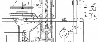
In Fig. Figure 2 shows a hydraulic diagram of a stand for testing hydraulic cylinders for strength under static load, break-out and idle pressure, external tightness and internal leaks. Before testing, be sure to check the performance of the hydraulic cylinder at idle speed. Hydraulic oils MGE46V (MG-30) according to TU 38-10150-79 or in winter MG-15V (VMGZ) according to TU 38-101479-88 should be used as hydraulic fluid. Oil filtration fineness: nominal 25 microns, when filling the stand tank - 10 microns. The highest oil temperature in the bench tank is allowed no higher than +65 °C for MG-15V and no higher than + 75 °C for MGE46V.
Due to economic transformations in our country, as well as the current situation, when certain specialized factories for the production of hydraulic cylinders were located in the CIS countries, a shortage of demand for hydraulic cylinders arose. Many machine-building plants that produce machines and equipment with hydraulic drives are forced to manufacture hydraulic cylinders for their own needs using existing metalworking equipment and additionally manufactured equipment.
Without special technological equipment for fine boring and rolling out the inner surface of the liners, grinding and polishing the rods, ensuring the roughness parameters in accordance with GOST 2789–73 of the working sealing surfaces of the rods and liners of hydraulic cylinders, as well as subsequent chrome plating of the outer surface of the rods by electrolytic application of a film 20...30 microns thick It is impossible to produce corrosion- and wear-resistant rods. The height of the unevenness of the outer working surface of the rod after chrome plating and polishing should be no more than Ra 0.160 microns, the working surface of the hydraulic cylinder liner - Ra 0.320 microns according to GOST 2789–73.
For a unified design of hydraulic cylinders at Pnom = 10, 16, 25 and 32 MPa, the industry standard OST 22-1417–79 provides the following series of outer diameters of liners (pistons) and hydraulic cylinder rods:
D = 30, 35, 40, 50, 63, 80,100, 110, 125, 140, 160, 180, 200, 250 mm;
d (at j = 1.6/2) = 10, 13, 15, 18/25, 22/32, 28/40, 36/50, 45/63, 50/70, 56/80, 63/90, 70/100, 80/110, 90/125, 100/140, 110/160 mm.
To manufacture hydraulic cylinders of modern technical level and quality, special metalworking and galvanic equipment, tools and highly qualified trained specialists are required. Consequently, the organization of a new production of hydraulic cylinders with an environmentally harmful galvanic section will require large financial costs. For most entrepreneurs, this path is difficult, if not impossible.
In technically developed countries, companies have taken a different path: they widely use components manufactured by specialized companies that have achieved a high technical level and product quality. Some manufacturers, after boring or broaching on special honing machines, carry out a fine finishing of the inner cylindrical surface of the liners or the outer surface of the rods, providing chrome plating and resistance to aggressive environmental influences; others manufacture pistons and front bushings with high precision; others offer any lugs and support bearings.
Particular attention is paid to the selection of wipers and seals, as well as support and guide rings, the manufacturers of which have achieved optimal performance of these elements in terms of their geometry, materials, and sequential arrangement in the sealing unit. As a result, the main manufacturer of hydraulic cylinders performs machining of parts for the subsequent assembly of a complete hydraulic cylinder with the parameters required by the customer. After assembly, the hydraulic cylinder is installed on a stand for acceptance testing, then packed in plastic or other packaging with a high degree of protection and sent to a warehouse for shipment to the consumer.
The outer diameters of cylinders and rods in most cases comply with regulatory documents. This allows mechanical repair plants and other service enterprises to use components to replace worn-out components and maintain a fleet of machines in operation without changing installation dimensions.
New technologies for the production of double-acting piston hydraulic cylinders significantly reduce financial costs, reduce production preparation time, and eliminate the need to use the environmentally harmful galvanic chrome plating process and waste disposal during chrome plating of rods.
It is more economically feasible to purchase components ready for assembly, which allows you to abandon ineffective and labor-intensive production operations, makes it possible to reduce personnel, transfer them to assembly work, and diversify the production of hydraulic cylinders of various sizes according to consumer orders.
The creation in Russia of production facilities for the assembly of piston hydraulic cylinders from foreign components is relevant and very timely. Today, the vast majority of factories producing construction, earth-moving and road equipment either purchase ready-made hydraulics, which are expensive, or create these units themselves using equipment that is far from perfect, and therefore their products are of poor quality.
In addition to rolled and honed pipes, chrome-plated rods, pistons, front bushings, lugs and support bearings, seals are imported from abroad to Russia, without which it is impossible to create a good hydraulic cylinder. When they talk about the low quality of Russian-made hydraulic cylinders, to a greater extent this refers to the quality of precisely such components.
(To be continued)
Characteristics of hydraulic cylinders
The main parameters of hydraulic cylinders can be divided into several groups.
Geometric parameters
- The diameter of the piston (liner), sometimes called the diameter of the hydraulic cylinder, the most common diameters are: 10, 12, 16, 20, 25, 32, 40, 50, 63, 80, 100, 125, 160, 200, 250, 320, 400 , 500, 620, 800 millimeters.
- Rod diameter, the following hydraulic cylinder rod diameters are standardized: 4, 5, 6, 8, 10, 12, 16, 20, 25, 32, 40, 50, 63, 80, 100, 125, 160, 200, 250, 320, 400, 500, 630, 800 millimeters.
- Stroke - the maximum possible movement of a piston with a rod or a hydraulic cylinder plunger
Typical hydraulic cylinder designs
Despite the huge variety of designs of hydraulic cylinders, there are typical solutions used in the design of hydraulic cylinders; we will consider some of them.
Hydraulic cylinder on studs
The front and rear covers of hydraulic cylinders of this design are connected by pins (anchors), the sleeve is sandwiched between the cylinder covers. The piston is sealed by two cuffs.
Round hydraulic cylinder
In the presented design, the covers are attached to round flanges secured by welding or threading to the sleeve. The type of piston seal shown in the illustration provides sealing in both directions.
Welded hydraulic cylinder
The covers are welded to the sleeve, the structure is non-separable and cannot be repaired. The cylinder has compact piston seals.
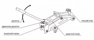
Tools and metal for creating a press with your own hands
- Welding tool
- Grinder or metal saw
- Bottle type jack
- Two springs
- A sheet of steel more than 8 mm thick will be used for the base of the structure
- A piece of steel pipe for constructing bushings for the rod head
- Channels, square and round tubes, angles
Once the drawing is ready and the list of materials has been prepared, we begin assembling the jack. At the first stage, we cut the metal in accordance with the values indicated in the drawing.
We assemble the main part of the press. We weld square pipes, get a rectangular frame and weld a steel sheet onto it. You should end up with a rectangle with a sheet of steel at the base. Do not forget to ensure that the angles of the structure are strictly 90 degrees. Next we need a movable platform that will hang on springs and will have a jack in it. In the upper part we need to create a thrust pad so that the jack rod does not jump out under load. On the movable platform itself, the walls should also be welded so that it is located strictly in the middle of the structure. To strengthen rigidity, it is recommended to weld corners onto the corners of the structure. We also need to weld the lower platform.