Features of the structure of the transformer core
The transformer is used to convert alternating current voltage.
It consists of a core with two or more windings. An alternating voltage is supplied to one of the coils. The current passing through it causes a change in time of the magnetic flux in the core. This flow penetrates all the windings and, according to the law of electromagnetic induction, induces an EMF in them. Depending on the ratio of the number of turns in the coils, the initial voltage in the secondary winding increases or decreases in comparison with the applied one.
The core is necessary for more efficient voltage transformation to reduce leakage losses.
The transformer core experiences significant exposure to an alternating magnetic field. This leads to the occurrence of eddy currents. As a result, the magnetic circuit heats up, which leads to energy loss.
The cores are made of steel, the magnetization reversal of which also leads to wasted energy consumption.
Current transformer in a magnetic field
The primary current converter in electricity metering devices is often a current transformer. When exposed to a constant magnetic field, the transformer, like the entire electric meter as a whole, acquires a negative error. The article presents the results of a study of the behavior of a current transformer when exposed to an external constant magnetic field of different induction.
Key words: current transformer, electricity meter, magnetic field, permanent magnet, saturation, error
Currently, one of the most common methods of stealing electricity is the use of permanent magnets, which are installed in close proximity to the electric meter. In this case, the power supply may stop functioning in electronic meters, but this especially affects meters that use a current transformer (CT) as a current sensor. The magnetic circuit of the CT becomes saturated under the influence of a strong constant magnetic field, as a result of which the CT acquires a negative error. This article describes experiments with CTs in a constant magnetic field and shows exactly how and to what extent the influence of a magnetic field affects the operation of CTs, as well as how the recorded electricity will change if such a CT is installed in an electricity meter.
- Current transformer design, operating principle
Current transformer (CT) is an electromagnetic device that converts alternating current of one magnitude into alternating current of another magnitude. Structurally, it consists of a magnetic circuit with two windings wound on it - primary and secondary. A current I1, called the primary current, passes through the primary winding of the current transformer. If the secondary winding is closed to a certain load, that is, a secondary circuit is connected to it, then in such a system “secondary winding - secondary circuit” under the influence of induced e. d.s. current I2 will flow - secondary [1]. The ratio of the primary and secondary currents is determined by the transformation ratio, which in turn is determined by the ratio of the number of turns of the primary and secondary windings
(1)
Here, are the primary and secondary currents; N1, N2 - number of turns of the primary and secondary windings, k - transformation ratio. In instrument current transformers, which are used in electricity meters, the primary winding is usually a live wire or bus carrying the measured current, which passes through the center of a torus-shaped core. The secondary winding is wound on the core and has a number of turns from several tens to several thousand. In this case, the secondary current turns out to be k times less than the secondary one and is supplied to the measuring circuits inside the meter. It is important that the secondary winding must be closed to a nominal resistance, which is several units or tens of Ohms, depending on the CT.
A current transformer, like any other measuring transducer, has errors. Due to the influence of the magnetizing current, as well as magnetic flux dissipation and losses on the magnetization reversal of the magnetic circuit, the real secondary current of the CT differs from the ideal one, determined by formula (1), according to which. Moreover, the real secondary current differs from the ideal one both in magnitude (amplitude, rms value) and in phase. Therefore, current and angular errors of CTs are distinguished [1]. If we represent the ideal and real secondary current in the form of complex numbers, then formally the errors can be defined as:
(2)
(3)
Here is the relative current error, and is the angular error. — rms current value, — current phase.
- Operation of CT in a magnetic field
When a CT is exposed to an external constant magnetic field, the magnetic circuit becomes saturated and its magnetic permeability decreases. In this case, the magnetic coupling between the primary and secondary windings weakens, and the CT acquires a negative error.
A typical magnetization characteristic of amorphous iron, from which the magnetic core of a current transformer is most often made, is shown in Figure 1 [2].
Rice. 1. Magnetic hysteresis loop of amorphous alloy GM515V
It can be seen that when the magnetic field strength H reaches a certain value, the magnetic induction B stops increasing and remains equal to the saturation induction value, which is determined by the type of magnetic material. That is, the magnetic material becomes saturated, and its magnetic permeability decreases significantly. This means that the CT transmission coefficient also decreases. Magnetic induction in a magnetic circuit consists of an alternating component caused by the primary current, as well as a constant component, which is determined by the external magnetic field. With a small induction value of the external magnetic field, the transformer reaches saturation only in certain phases, when the primary current and the magnetic field generated by it have the greatest instantaneous value. At these moments, the total magnetic induction in the magnetic circuit reaches the saturation induction value. This leads to the fact that the secondary current is distorted and its rms value decreases compared to the value without an external magnetic field. With a further increase in the external magnetic field, the magnetic circuit becomes more saturated, for a wider range of instantaneous values of the primary current. With a large induction of the external magnetic field, close to the saturation induction, the magnetic circuit is in saturation for any value of the primary current, and the CT becomes similar in characteristics to an air transformer with a magnetic permeability of about unity. The secondary current drops to almost zero.
An experiment was conducted to evaluate the current error. A DCT104W current transformer with a maximum primary current of 100A was taken. Its rated load is 12 Ohms, transformation ratio is 2500. The primary current supplied to the transformer was set in the experiment from the measuring generator UPPU-ME 3.1 [3]. The value of the specified current in this experiment was equal to .
Since the secondary winding of the CT is closed to the rated load (resistor), to estimate the error it is more convenient to measure the voltage drop across it, which in any case is proportional to the secondary current. Voltage measurements were made with a multimeter. The ideal value was calculated based on the CT transformation ratio (formula 1), the specified primary current and the value of the load resistance (a precision resistor was used, class 0.1).
(4)
The relative current error of the transformer when exposed to a magnetic field was determined by the formula
(5)
— measured voltage across the load resistor when exposed to a constant external magnetic field.
A neodymium magnet with an adhesive force of 100 kg was used as a source of magnetic field. It was brought to the current transformer at different distances, which were regulated. The experimental setup diagram is shown in Figure 2.
Rice. 2. Diagram of the experimental setup, determination of the current error
A graph of the dependence of the relative current error of the current transformer caused by a constant external magnetic field on the distance to the magnet is shown in Figure 3.
Rice. 3. Dependence of the relative current error of the CT on the distance to the magnet
The graph shows that already starting from a distance of 22–23 mm between the magnet and the CT, the current error of the transformer begins to increase rapidly and reaches -92% in the case when the magnet is located close to it.
In addition, the phase difference between the primary and secondary current was measured. For measurements, voltages proportional to these currents and in-phase with them were used, respectively, on the shunt in the primary winding and on the load resistor in the secondary (Figure 4).
Rice. 4. Diagram of the experimental setup, determination of the angular error
According to [1], the phase difference between the primary and secondary current should ideally be 180°. However, measurements have shown that when exposed to a constant external magnetic field, it reaches , that is, the current transformer essentially turns into an air transformer, as noted above. A graph of the dependence of the angular error on the distance to the magnet is shown in Figure 5. The phase difference was assessed by the difference in the time it took both signals to pass through zero on the oscillogram.
Rice. 5. Dependence of the angular error of the CT on the distance to the magnet
As was shown above, with a low induction of the external magnetic field (distance to the magnet of 23–23 mm or more), the magnetic circuit does not reach the saturation stage and the characteristics of the CT do not change. When the distance from the magnet to the CT decreases to 15–20 mm in certain phases of the primary current, the magnetic circuit begins to saturate, which leads to the appearance of significant current (up to 70%) and angular (up to 80°) errors. When the magnet is brought to the CT at a distance of 10 mm or closer, the magnetic circuit is in a state of saturation at almost any primary current and the CT operates like an air transformer. The current error is more than 90%, the angular error is 90°.
It is known that active electrical power is proportional to voltage, current and cosine of the phase difference between them, that is
(6)
If the current sensor in a device that measures power is a current transformer, and it gives a significant negative current error, as well as an angular error, then the power measurement result will also have a significant negative error (as they will also change in formula 6).
If a CT, in the presence of an external constant magnetic field, gives a current measurement with an error in amplitude and phase in accordance with the graphs shown in Figures 3 and 5, then the relative error in measuring power by a device using such a CT, depending on the distance to the magnet, will have the form shown in Figure 6.
Rice. 6. Dependence of the relative error of active power on the distance to the magnet
From the graph shown in Figure 6, it is clear that at a distance to the magnet of 15 mm and closer, the error in measuring active electrical power is close to 100%.
Due to this effect, electricity is stolen when a strong permanent magnet is installed directly on an electricity meter. Conclusion
Thus, the experiments have shown that if a current transformer is used as a current sensor in an electricity meter, then with the help of a strong permanent magnet it is possible to ensure that the consumed electricity is practically not taken into account by the device. Experiments have shown that when using a DCT104W current transformer, it is enough to bring a neodymium magnet with an adhesive force of 100 kg to a distance of 15 mm to achieve the specified effect. Obviously, when using a stronger magnet, a greater distance will be sufficient. Therefore, to protect against theft of electricity in this way, it is not enough to simply increase the distance between the current transformer and the wall of the device case: there will still be a magnet that will be able to saturate the transformer. To protect against this type of theft, special electronic circuits, screens, or other types of current sensors should be used.
Literature:
- Afanasyev V.V., Adonyev N.M., Kibel V.M. et al. Current transformers (2nd edition); L.: Energoatomizdat. Leningrad branch, 1989.
- Amorphous metal materials. Power electronics, No. 2, 2009. [Electronic resource]. https://www.power-e.ru/2009_2_86.php (date accessed 04/15/2017)
- Universal verification unit "UPPU-ME". Passport, MS2.702.500.PS, 2014.
How to reduce losses
The magnitude of magnetization reversal losses depends on several factors:
- properties of the substance from which the core is made. Materials that are difficult to magnetize are also difficult to remagnetize. And the more energy is consumed, which is expressed in heating;
- magnetization reversal frequencies;
- the highest value of magnetic induction.
Losses are reduced through the use of special transformer steel. It requires less energy for magnetization reversal compared to other substances.
Eddy currents reach their greatest values in massive conductors due to their low resistance. To reduce them, it is necessary to increase the electrical resistance. This is achieved by assembling a core from separate sheets. The thickness of the steel plates is selected to be no more than 0.5 mm.
To prevent the sheets from melting together when heated, the plates are isolated from each other to reduce eddy current losses. Varnish and scale are used as a separator. There are chemical methods for insulating steel sheets. The interlayers provide strong resistance to eddy currents and stop their effect, which significantly reduces energy losses.
What are they, transformers of the future?
The transformer industry is considered to be quite conservative. Nevertheless, it also has to reckon with revolutionary changes in the field of electrical engineering, where nanotechnology is making itself known more and more loudly. Like many other devices, they are gradually getting smarter.
Gas transformers
An active search is underway for new structural materials – insulating and magnetic – that can provide higher reliability of transformer equipment. One direction could be the use of amorphous materials, which will significantly increase its fire safety and reliability.
Explosion- and fire-proof transformers will appear in which chlorinated biphenyls, used to impregnate electrical insulating materials, will be replaced by non-toxic liquid, environmentally friendly dielectrics.
Gas transformers
An example of this is SF6 power transformers, where the function of the coolant is performed by non-flammable SF6 gas, sulfur hexafluoride, instead of the far from safe transformer oil.
It’s a matter of time to create “smart” power grids equipped with semiconductor solid-state transformers with electronic control, with the help of which it will be possible to regulate the voltage depending on the needs of consumers, in particular, connect renewable and industrial power sources to the home network, or, conversely, turn off unnecessary ones when they are not necessary.
Another promising area is low-temperature superconducting transformers. Work on their creation began back in the 60s. The main problem faced by scientists is the enormous size of the cryogenic systems required to produce liquid helium. Everything changed in 1986, when high-temperature superconducting materials were discovered. Thanks to them, it became possible to abandon bulky cooling devices.
Transformer with semiconductor converter
Superconducting transformers have a unique quality: at high current densities, losses in them are minimal, but when the current reaches critical values, the resistance from zero level increases sharply.
Main types of cores
Transformers have different areas of application, technical characteristics, and dimensions.
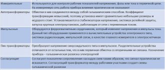
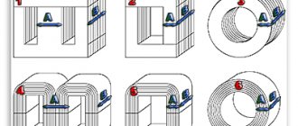
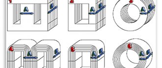
They also differ in the type of magnetic circuits. Structurally, the cores are divided into three main types: The rod core is designed in the shape of the letter P and consists of two rods connected by a yoke. If necessary, protect the windings from external influences using armored magnetic cores. The yoke is located on the outer part and completely covers the rod with the winding located inside.
Cores are also classified according to the method of assembling the plates:
- set of stamped plates. The advantages of magnetic cores made from sheets include the possibility of their manufacture from not very durable materials;
- wound metal tapes. Such cores utilize magnetic energy more fully, but at the same time have an increased level of losses. Toroidal winding of tapes is the most complex, but energetically the most favorable.
There are differences in the connection of the rods to the yoke. They are collected in two ways:
- end-to-end, when all elements are assembled from plates separately. They are connected into a single core at the last stage of transformer assembly: after the windings are laid;
- intertwined. Such magnetic cores are called laminated. They have almost no losses at the connection points.
Voltage transformers
This is perhaps the most numerous type of transformer family. In a nutshell, their main function is to make the energy produced in power plants available for consumption by various devices. For this purpose, there is a power transmission system consisting of step-up and step-down transformer substations and power lines.
First, the electricity produced by the power plant is supplied to a step-up transformer substation (for example, from 12 to 500 kV). This is necessary in order to compensate for the inevitable losses of electricity during transmission over long distances.
The next stage is a step-down substation, from where electricity is supplied via a low-voltage line to a step-down transformer and then to the consumer in the form of a voltage of 220 V.
But the work of transformers does not end there. Most of the household electrical appliances around us - PCs, TVs, printers, automatic washing machines, refrigerators, microwave ovens, DVDs and even energy-saving light bulbs have step-down transformers. An example of an individual “pocket” transformer is a mobile phone (smartphone) charger.
The huge variety of modern electronic devices and the functions they perform correspond to many different types of transformers. This is not a complete list of them: power, pulse, welding, separating, matching, rotating, three-phase, peak transformers, current transformers, toroidal, rod and armor.
Features of impulse loads
For devices carrying pulsed loads, special transformers are used. They are capable of converting voltage and current under pulsed loads and withstanding their destructive effects. The types of cores of pulse transformers do not differ in shape from other types of devices.
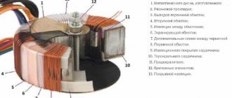
Most often, the magnetic core is made in the form of a ferrite torus. The windings are wound on it in a special way: in the primary coil they are laid counterclockwise, and in the secondary coil they are laid clockwise.
Such a transformer can be made independently; you just need to take into account the requirements for conservation of momentum.
Application area
Household appliances have contact with ground via a neutral wire. Simultaneous contact by the consumer of the phase current and the neutral circuit leads to a short circuit and injury. Connecting through an isolation transformer allows you to protect a person, since the secondary winding does not contact the ground.
Pulse units are used to transmit a rectangular impulse and transform short signals under load. At the output, the polarity and amplitude of the current changes, but the voltage remains unchanged.
DC measuring equipment is a magnetic amplifier. The directional movement of low-power electrons helps change the alternating voltage. The rectifier supplies constant energy and depends on the input electricity values.
Power units are widely used in small current and power generators; the performance in diesel engines is average. Transformers are mounted in series with the load, the device is connected to the source via the primary winding, and the secondary circuit produces the converted energy. The output current value is directly proportional to the load. Equipment with 3 magnetic rods is used if the generator is three-phase.
Inverting units have transistors of the same conductivity and amplify only part of the signal at the output. To completely convert the voltage, a pulse is applied to both transistors.
Matching equipment is used to connect to electronic devices with high resistance at the input and output of loads with low electrical transmission. The units are useful in high-frequency lines, where the difference in values leads to energy losses.
Converter power calculation
Each transformer has technical characteristics specified in the passport. It may be necessary to carry out independent winding and power calculations if the data is lost. The power value is important to determine whether a particular inverter can be used.
Before determining the power of the transformer based on the cross-section of the core, the type of magnetic circuit is studied. If the core has a W shape, perform the following calculations:
- measure the thickness of the set of plates;
- measure the central part;
- the results obtained are multiplied.
What is a magnetic core in a transformer? Why is there a gap needed and more?
Mains and pulse transformers have a core or magnetic circuit made of different materials; this article will talk about this detail.
A magnetic core is a part of a transformer designed to pass a magnetic flux. This flux in a network transformer appears when the primary network winding is connected to a 220V network, which has a sinusoidal voltage waveform. An electromagnetic field is formed near this coil, the magnetic component of which is transmitted by the magnetic core and it becomes a magnet whose poles change 50 times north and 50 times south in one second. If you insert another step-down coil onto the magnetic circuit, then when a load is connected to it, an emf is induced in it.
If you measure the resistance of the TS-180 network winding, the readings will be about 6.4 Ohms, and if you take a 6.4 Ohm resistor and plug it into a 220V network, it will break or blow out the plugs. The fact is that the resistance of the resistor is active, this will be shown by the ohmmeter, and the resistance of the network winding at an alternating voltage of 220V is reactive, and it is precisely this that provides the resistance of 220V. The core in the coil increases the reactance and inductance of the winding.
The magnetic core is made of special transformer steel-iron with silicon (soft magnetic material), with high resistivity and minimal residual magnetization, a narrow hysteresis loop, and high magnetic permeability. The magnetic core is affected by Foucault currents, to reduce them the core is overlapped and laminated, and the plates are insulated from each other with varnish or a layer of oxide. The high resistivity of the core is also due to Foucault currents.
You cannot use another steel in the core, it will start to heat up and the transformer will not work well. The core may go into saturation, this is when the magnetic circuit becomes a magnet as much as possible. In this mode, the transformer will begin to emit impulse noise, which can affect the operation of radio components.
To operate in switching power supplies, a ferrite core is used, which can operate at frequencies of tens of kHz with pulses. This is also a ferromagnet, but is made of iron oxide and other additives and materials. It is not overlapped, since the Foucault currents in the core are extinguished due to due to the high resistivity of the material. The gap is made so that the core does not become saturated from magnetization, which can be caused by the constant component of the signal (non-magnetic gap).
Network and pulse transformers can be wound on a toroidal core to reduce stray fields. They are more efficient compared to conventional cores and have smaller dimensions, but winding on rings is labor-intensive, and on a ferrite ring it is also more difficult to create a gap, although it is commercially available rings with clearance.
The magnetic antenna has a ferrite core. Marking 400NN. 400 is the magnetic permeability, the higher it is, the lower the operating frequency of the ferrite. In microwaves, the core in the circuits is brass or aluminum.
Installation, connection, dangerous factors
If the insulation of the windings breaks down, the possibility of electric shock arises, but the risk is prevented by grounding the output (indicated on the housing) of the secondary.
The currents at the terminals of the secondary coil I1 and I2 are polar; they must be permanently connected to the load. Energy flowing through the primary circuit with significant potential (S=UI). In the other, a transformation occurs, and when it breaks, the tension drops there. The potential of open ends when energy flows is high, which poses a significant danger.
For the reasons described above, all secondary CT circuits are assembled especially carefully and reliably; shunt short circuits are always installed on them and cores taken out of operation.
How is the TT connected?
There are several schemes for protective products. Let's consider connecting a CT to three-phase voltage.
Full star:
- the most common, protection of single- and multi-phase systems against short circuit;
- three CTs are connected into a star.
If the current is below the settings on relays KA1–KA3, then this is a normal situation, the protection is not activated. The current at K0 is the sum of all 3 phases. As the values in one of them increase, the current in the CT also increases. The relay will operate in case of short circuit and when the load is exceeded.
Partial star:
- protection against phase-to-phase faults to create circuits with a neutral grounded;
- for low power receivers with other protection options.
Delta and star circuit - for differential protection.
A circuit without de-energizing during a ground fault is used, but rarely for the same reason. For protection against short circuits between phases and surges in one of them.
TTIs are connected by simple serial connection of the primary turns of the product.
Installation
Installation of current transformers:
- Inspection of the device, checking the insulation (must be above 1 kOhm per 1 V);
- Switch off the power supply;
- Make sure there is no power, fix the grounding.
- Marking, installation of fasteners. It is prohibited to place the transformer close to the power plant (minimum gap - 10 cm).
- Signs and fences are put up.
- The primary turns are connected in series, but with a load on the secondary ones. If it is not possible to connect the meter, then its contacts are closed so that there is no high power on it, which will damage it.
The CT does not allow idle operation; its mode is close to short circuit: the secondary turns are necessarily closed when the device is connected to the measured current. Otherwise, overheating occurs, damaging the insulation. Before disconnecting the meters, first short-circuit the coils. Some models have terminals and jumpers for this purpose.
Calculation
The current transformer can be calculated using online calculators and selected according to its nominal value (for example, for 10 kV). But these are too simplified tools. Calculus and parameters to choose from is an extremely broad topic, so let's cover the basics.
Accuracy is extremely important, so careful calculations by specialists will be required. You need to know many specific nuances, for example:
- for different connection schemes and types of short circuit, there are different formulas for determining resistance;
- check the primary current for thermal and electrodynamic resistance;
- There are some nuances for CTs, for relay protection and for accounting purposes and measurements.
Rules for choosing a current transformer in general terms:
- the rated operating voltage of the CT must exceed or be compared with the rated power plant (standard values 0.66, 3, 6, 10, 15, 20, 24, 27, 35, 110, 150, 220, 330, 750 kV). If the equipment being serviced has 10 kV, then the product must be designed for this indicator;
- the primary current of the CT is greater than the rated current of the power plant, but taking into account the overload capacity;
- CTs are assessed by the rated power of the secondary load, which must exceed its calculated value. (Snom>=Sload);
- evaluate the dimensions and location for installation, rated loads (there is a table), time to failure, service life, accuracy class.
Check after calculation
Rules:
- After calculation, the CT is checked by loading at max. and min. values of loads flowing through it;
- according to clause 1.5. 17 PUE at max. connected load, the current in the secondary coil is at least 40% of the meter rating, at min. — not less than 5%;
- Max. the load should be from 40%, and min. - from 5%, and in any case it should not exceed 100%, otherwise the transformer will be overloaded;
- if the calculated values of max./min. loads are less than 40% and 5%, respectively, then you need to select a product with a lower rating, and if this cannot be done according to the parameters of max. load, it is necessary to provide for the installation of two meters - for max. and min. loads.
A little history
Thanks to the English physicist Michael Faraday, in 1831, humanity became acquainted with electromagnetic induction. The great scientist was not destined to become the inventor of the transformer, since his experiments involved direct current. The prototype of the device can be considered the unusual induction coil of the Frenchman G. Ruhmkorff, which was presented to the scientific world in 1848.
In 1876, Russian electrical engineer P. N. Yablochkov patented an alternating current transformer with an open core. The device owes its modern appearance to the English brothers Hopkinson, as well as the Romanians K. Tsiperanovsky and O. Blati. With their help, the design acquired a closed magnetic circuit and has preserved the circuit to this day.
Types of magnetic cores
Design and operating principle
Mandatory elements of almost any voltage conversion device are insulated windings formed from wire or tape. They are located on a magnetic circuit represented by a core made of ferromagnetic material. Communication between the coils is carried out using magnetic flux. When working with high-frequency currents (100 kHz or more), there is no core.
Transformer operating principle
The operating principle of a transformer combines the basic postulates of electromagnetism and electromagnetic induction. It can be considered using the example of a simple device with two coils and a steel core. The supply of alternating voltage to the primary winding leads to the appearance of a magnetic flux in the magnetic circuit, after which an induced emf appears in the secondary and primary windings; if you connect a load to the secondary winding, current will flow. The frequency of the output voltage remains unchanged, and its value depends on the ratio of the turns of the coils.
Transformers can be step-up and step-down, to determine this you need to find out the transformation ratio , with its help you can find out which transformer. If the coefficient is less than 1, then the transformer is step-up (this can also be determined by the values; if there is more in the secondary winding than in the primary, then it is step-up), and vice versa, if K>1, then it is step-down (if there are fewer turns in the primary winding than in the secondary).
- U1 and U2 – voltage in the primary and secondary windings,
- N1 and N2 – number of turns in the primary and secondary windings,
- I1 and I2 – current in the primary and secondary windings.
How to calculate
Almost any calculations must begin with core measurements. Figures 2, c and 3 show the quantities that need to be measured at the BT in a schematic and visual display, respectively.
Rice. 2 – Measurement of core dimensions according to the diagram.
Rice. 3 – Measuring the dimensions of the core by appearance.
Secondary power
P2 = 2 * Pgab – P1,
where Pgab is the overall power (W), P1 is the power of the primary winding (W).
Overall power
Pgab = (n * Sc * So * 4.44 * f * B * j * Km * Ks) / ((1 + n) * 100),
where n is the tabulated efficiency of the transformer, Sc is the cross-sectional area of the magnetic core (cm²), So is the cross-sectional area of the window (cm²), f is the frequency (equal to 50 Hz), B is the magnetic induction (T), j is the tabulated current density in coil wires (A/mm2), Km – coefficient of filling of the magnetic circuit window with copper, Kс –…steel.
Actual steel section
Sc = a * b,
where a is the width of the rod, b is the thickness of the magnetic circuit according to Figure 2 or 3.
Actual cross-sectional area of the core window
So = h * c,
where h is the height of the window, c is the width of the window according to Figure 2 or 3.
The value of the rated current of the primary winding
P1 = U1 * I1
where I1 is the current in the primary winding (A).
Rated current in windings
I = Spr * j,
where Spr – wire cross-section (mm²).
Winding wire cross-section
Spr = 3.14 * R²,
where I is the current in the winding (A), R is the radius of the wire (mm).
Diameter of winding wires without insulation
d = 2 * √ (I / (3.14 * j))
Number of turns of each winding
W1 = U1 / u1
W2 = U2 / u2,
where W1 is the number of turns of the primary, W2 - ...secondary, U1 - the value of the input voltage on the primary (V), U2 - the output voltage on the secondary (V), u1 - the value of the voltage on one turn of the primary (V), u2 - ... the secondary (V ).
Number of turns per volt
w1 = W1 / U1
w2 = W2 / U2
For the same wire we have the same values in both windings, that is:
w1=w2
The maximum power that the magnetic circuit can provide
Pmax = Sc²
Operating modes
The characteristics of transformers are determined by operating conditions, where the load resistance plays a key role. The following modes are used as a basis:
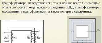
- Idle move. The outputs of the secondary circuit are in an open state, the load resistance is equal to infinity. Measuring the magnetizing current flowing in the primary winding makes it possible to calculate the efficiency of the transformer. Using this mode, the transformation ratio is calculated, as well as losses in the core;
- Under load (working). The secondary circuit is loaded with a certain resistance. The parameters of the current flowing through it are directly related to the ratio of the turns of the coils.
- Short circuit. The ends of the secondary winding are short-circuited, the load resistance is zero. The mode informs about losses that are caused by heating of the windings, which in professional language is referred to as “copper losses”.
Short circuit mode
Information about the behavior of the transformer in various modes is obtained experimentally using equivalent circuits.
Checking a step-down transformer with a multimeter
Let's say a 4-pin transformer - two wires from the primary winding and two from the secondary. Checking it comes down to identifying damage in the windings. To determine whether there are any, first we’ll switch the multimeter to diode testing mode or move the switch to the resistance scale. Then we check one coil, without paying attention to the polarity of connecting the probes, since in this case it is absolutely not important. We do the same with the second one.
Low ohmmeter readings will indicate the serviceability of the windings; lack of tester response will indicate the opposite.
If the affiliation of a particular contact to any of the windings is not known, then it is established during the testing process - the resistance in the primary of the step-down transformer should be slightly higher.
Classifications
Transformers are classified according to a number of parameters, such as:
- Purpose. Used: for changing voltage, measuring current, protecting electrical circuits, as laboratory and intermediate devices.
- Installation method. Depending on the location and mobility, the transformer can be: stationary, portable, internal, external, support, busbar.
- Number of steps. The devices are divided into single-stage and cascade.
- Rated voltage. There are low and high voltage.
- Winding insulation. The most commonly used are oil-paper, dry, and compound.
In addition, converter devices come in different types, each of which has its own classification system.
Power
The most widely used the power transformer . Devices with direct conversion of alternating voltage, designed for high power, are in demand in various areas of the electric power industry. They are used on power lines with voltages of 35–1150 kV, in city power networks operating with voltages of 6 and 10 kV, and in providing end consumers with voltages of 220/380V. The devices provide power to all kinds of electrical installations and devices in the range from fractions to hundreds of thousands of volts.
Power transformer
Measuring
Current transformers (CTs) reduce the current to the required levels. The scheme of their operation is distinguished by the sequential connection of the primary winding and load. At the same time, the secondary winding, which is in a state close to a short circuit, is used to connect measuring instruments, actuators and indicator devices. With the help of TA, galvanic isolation is carried out, which makes it possible to avoid using shunts during measurements.
High voltage CT(left) and low voltage CT(right)
With the help of voltage transformers (VT) , the same as TA only in voltage. In addition to converting input parameters, electrical equipment and its individual elements are protected from high voltage.
High voltage transformer (left) and low voltage transformer (right)
Pulse
If it is necessary to convert pulsed signals, pulse transformers (IT) are used. By changing the amplitude and polarity of the pulses, the devices maintain their duration and practically do not affect the shape.
Autotransformer
In autotransformers, the windings form one circuit and interact through electromagnetic and electrical communication. Unlike other types of converters, devices can contain only 3 outputs, allowing you to operate with different voltages. The devices are distinguished by their high efficiency, which is especially noticeable with a slight difference in input and output voltage.
Single-phase (left) and three-phase (right)
Without galvanic isolation, representatives of this type increase the risk of high-voltage shock to the load. A prerequisite for the operation of devices is reliable grounding and a low transformation ratio. The disadvantage is compensated by lower consumption of materials during manufacturing, compactness and weight, and cost.
Dividing
For isolation transformers, interaction between the windings is eliminated. The devices increase the safety of electrical equipment in the event of damaged insulation.
Isolation transformer
Coordinator
Matching transformers are used to equalize resistance between stages of electronic circuits. While maintaining the signal shape, they play the role of galvanic isolation.
Peak transformer
Using a peak transformer, sinusoidal voltage is converted into pulse voltage. In this case, the pulses change polarity with each half-cycle.
Twin throttle
A feature of a dual inductor is the identity of the windings. The mutual induction of the coils makes it more efficient than standard chokes. The devices are used as input filters in power supplies, audio and digital equipment.
Twin throttle
Welding
In addition to the above, there is the concept of welding transformers. Specialized devices for welding work lower the voltage of the household network while simultaneously increasing the current, measured in thousands of amperes. The latter is adjusted by dividing the windings into sectors, which affects the inductive reactance.
Welding transformer
Varieties
There are many types of CTs, but in the most general form, the choice of current transformers takes into account that products are divided into measuring ones (TTI) and for protection.
Separation factorSpecies
| Purpose |
|
| Design | In windings, the primary is connected in series to the conductor being measured. In toroidal ones, instead of it there is a network line (in the CT hole), and in rod ones, in its role there is a circuit cable, which is equivalent to 1 turn. |
| Installation |
|
| Number of turns |
|
| Insulation |
|
| steps | One or more (cascaded) |
| At what denomination | Up to 1 kV and higher (for example, for current 10 kV) |
The current transformer can be configured to be opened, installed and locked, without shutting down, in online mode.
Protective CTs
Protective transformers are usually of the relay type, “monitoring” that the person carrying out manipulations who enters the electrical network of the power plant does not receive a fatal blow. Inside electrical systems that create, transport, distribute energy, there are dangerous values for correct operation. But any equipment requires inspection, repair, and maintenance, so a safety “window” in the form of TT is left for repair specialists.
Measuring CTs
The task of the measuring current transformer TTI is to convert values, creating the ability to connect a voltmeter, ammeter, or other meter without fear that it will burn out from excessive load. In this case, the most accurate and reliable measurement data is obtained. In other words, the TT isolates the connected device, not only for measurements, but also any other device as needed, from high powers.
Decoding the main parameters
The diversity in design and wide range of parameters of transformers have led to the need for their marking according to a special standard. Without having a technical description at hand, the characteristics of the device can be determined by the information printed on its surface, expressed in an alphanumeric code.
The marking of power transformers contains 4 blocks.
You can download and view GOST 15150 here (will open in a new contribution in PDF format): View file
Let's decipher the first three blocks:
Decoding of markings: 1,2,3 blocks
- The first letter "A" is attached behind the autotransformers. In its absence, the letters “T” and “O” correspond to three-phase and single-phase transformers.
- The further presence of the letter “P” informs about devices with split winding.
- The third letter means cooling; the oil natural cooling system is assigned the letter “M”. Natural air cooling is marked with the letter “C”, oil cooling with forced airflow is designated “D”, with forced oil circulation – “C”. The combination “DC” indicates the presence of forced oil circulation with simultaneous air blowing.
- The letter “T” marks three-winding converters.
- The last sign characterizes the features of the transformer:
- “N” – on-load tap-changer (voltage regulation under load);
- space – switching without excitation;
- “G” – lightning protected.
Transformers price
The price of a transformer varies widely and depends on many factors. This takes into account the type and purpose, power and other electrical parameters. The cost of devices is reflected in the complexity of production and the materials used. Protection and other features are also important.
A transformer from a well-known manufacturer cannot be cheap. However, the buyer can be sure that the device he purchased fully complies with the specified characteristics, will not fail the first time it is turned on, and is guaranteed to work out its intended life.
High-voltage transformers can be assessed by their power, that is, if the power of a transformer is 63 MW (63,000 kVA), then it costs about 63 million rubles, but this is an approximate estimate .
Video: How to check the health of a transformer
Classification of installations
The division of equipment into classes depends on various parameters.
It can be carried out by:
- Purpose;
- Installation method;
- Number of steps;
- Type of insulation;
- Rated voltage.
Based on the features of use, devices are:
- Measuring;
- Protective;
- Intermediate.
Moreover, the former are divided into current and voltage transformers.
Let's watch the video, the principle of operation and types of transformers:
As for installation, such equipment can be located not only indoors, but also outdoors. Therefore, based on this parameter, the following types of devices are distinguished:
- External;
- Internal;
- Stationary;
- Portable.
The winding insulation of transformers can be either dry, paper-oil or compound. There are differences in the number of steps. Depending on this parameter, devices are divided into:
- Single stage;
- Cascade.
Another distinguishing feature of different models can be the voltage rating. According to its meaning, transformers are classified into low and high voltage.
In addition, power devices can be connected to single or three-phase electrical networks.
High voltage transformers are most often oil cooled. Devices in this series are characterized by high efficiency and good protection against overheating. They require minimal maintenance during operation.
According to their design, power transformers are divided into having the following types of inputs:
- With main porcelain shell insulation;
- With oil barrier;
- With paper-oil;
- With polymer.
- Condenser feedthroughs;
Characteristics and calculation of the transformer
Typically, the main parameters of the device are indicated in the technical documentation included with it. For transformers these are:
- Power and voltage (nominal);
- Maximum winding current;
- Dimensions;
- Weight.
Let's take a closer look at what they mean. The rated power of the device is calculated and indicated by the manufacturer. It is expressed in kilovolt-amperes.
The rated voltage consists of a primary voltage, for which the corresponding winding is designed, and a secondary voltage, measured at the terminals. The value of this parameter can change up to 5% down or up. It can be determined by performing a simplified calculation of the power transformer.
Watch the video and make the correct calculation:
The rated power and current of the device must comply with existing GOST standards. Today, dry models are produced in which this indicator may have the following meaning:
- 160;
- 250;
- 400;
- 630 kVA.
The power of the device is usually indicated in the device passport, and knowing it, you can calculate the rated current value. The following formula is used for this:
I=S√3U, where the values S and U indicate the rated power and voltage.
Based on which winding the current value is calculated for, the quantities included in the formula will also change. It is better to entrust the calculation of the power transformer power to the load to specialists. This will allow you to avoid unpleasant moments during operation.
In addition, the nominal voltage is considered to be the value of the linear value at no load on both windings. Current values are calculated based on the power of the device. When choosing equipment, you should take into account that the calculation of a power toroidal transformer will differ slightly from that given above. You can find information on this issue on the Internet.
Features of installation and operation
Most models of power equipment have a significant weight. Therefore, they are delivered to the installation site by special transport. Moreover, the equipment is delivered assembled and completely ready to be switched on.
Watch the video, starting and diagnosing the equipment:
The device is installed on a pre-prepared foundation or in a special room. To prevent air pockets from forming under the tank cover when installing the device, steel plates are placed under the rollers. Their thickness should be such that a rise of 1% is obtained on the narrow and 1.5% on the wide side of the transformer. The length of the gaskets starts from 150 mm. If the weight of the device does not exceed 2 tons, then it is installed directly on the foundation. Its body must be connected to the grounding network.
However, it should be remembered that before installation the device is tested in laboratory conditions. In the process of carrying out this work, the transformation ratio is measured and the quality of connections is checked. They also test the device with increased insulation voltage and check the conformity of the transformer oil.
After delivery to the site, the device undergoes an external inspection. At the same time, pay attention to the absence of oil leaks and extraneous noise during operation. The condition of the bushings and contact connections is checked for heat damage.
After starting the transformer, it is necessary to periodically monitor the temperature. Measurements are performed using glass thermometers. They are immersed in a special sleeve located on the lid of the device. The temperature here should not exceed 95°C.
To avoid emergency situations in the operation of the transformer, it is necessary to regularly measure the loads. This will allow you to determine phase imbalances leading to voltage distortion. Inspection of equipment without shutting it down should be performed every six months. But depending on the condition of the device, the timing may vary.
What is a transformer core: structure and types of magnetic circuits
A transformer is installed in electrical networks to convert alternating current voltage. The main parts of the device are the core and windings. Windings are coils that are wound of conductive metal around a core. For these purposes, copper or aluminum is most often used. Under load, voltage is applied to the primary winding. The current passes through the winding and causes a magnetic flux to appear in the core. As a result, voltage also arises in the second winding. And its value depends on the number of turns of wire on the primary and secondary windings.
Purpose and application
Armored transformers are not labor-intensive and cheap to manufacture, and for signal small/medium power (up to 100 W) transformers, the armored type is usually chosen. BT, however, are also the most sensitive to interference, and they also have a large leakage inductance. The ShL and ShLM series are used when the smallest weight, rated power of no more than 100 W and a frequency of 400 Hz (ShL) or 50 Hz (ShLM) are needed. The ShLO series is used in low voltage conditions at frequencies from 1 to 5 kHz and high voltages at frequencies from 50 Hz to 5 kHz.
The Soviet tape small-sized low-power transformer - TPP - is distinguished by low voltages on the secondary windings. TPPs perform well in circuits of household appliances, in radio-electronic and communication devices, and computer systems powered by industrial and special networks with alternating current at voltages of 40, 115, 127 and 220 V and a frequency of 50 or 400 Hz. They are characterized by a wide range of voltages and currents with a power of up to 500 VA.
What is the magnetic core of a transformer and why is it needed?
The magnetic circuit or core of the transformer allows voltage to be converted more efficiently, while reducing losses. For the manufacture of cores, special ferromagnetic steel is used.
Types of transformer cores
According to their structure, cores are divided into:
The rod core has the shape of the letter P. The windings are mounted on the rods, and the rods themselves are connected by a yoke. This design of the magnetic circuit makes it easy to inspect and repair the windings. Therefore, this type is typical for medium and powerful transformers.
W-shaped armor core The windings are located on the central rod. Armor transformers are more difficult to manufacture. And repairing the windings in them is not as easy as in rod ones.
The toroidal core has the shape of a ring with a rectangular cross-section. The windings are wound directly onto it. Therefore, this type of core is considered the most energy efficient.
a – rod core, b – armor core, c – toroidal core.
Transformer equivalent circuit
To calculate the electrical parameters of a transformer, various equivalent circuits are used. These schemes must meet the following conditions:
- the circuit must take into account the most significant electromagnetic processes and ensure sufficient accuracy of the calculated characteristics of various transformer modes;
- the circuit must be described by low-order equations so that the relationship between the electrical characteristics and design parameters of the transformer is explicitly determined.
Due to the inconsistency of these conditions, it is possible to omit from the calculations a number of design parameters that have little effect on the electrical characteristics of the transformer. In addition, during the practical implementation of a transformer, its design dimensions always differ to one degree or another from the calculated values.
Therefore, to analyze and calculate the transformer, use the equivalent transformer circuit shown below
Equivalent equivalent circuit of a two-winding transformer.
This scheme uses the following parameters:
LC is the magnetizing inductance of the transformer, which takes into account the energy storage in the main flow of mutual induction in the magnetic circuit when voltage is applied to the primary winding,
RC is the equivalent resistance of active losses in the magnetic circuit due to magnetization reversal and eddy currents,
LS1 and L'S2 – leakage inductance of the primary winding and reduced inductance of the secondary winding, taking into account the energy storage in leakage fluxes,
R1 and R'2 – active resistance of the primary winding and reduced resistance of the secondary winding, taking into account energy losses when load current flows through them,
С01 and С'02 – own capacitance of the primary winding and reduced capacitance of the secondary winding,
C12 – interwinding capacitance of the transformer.
Taking into account this equivalent circuit, we write down the equations of operation of the transformer
Most of the parameters of the transformer equivalent circuit are calculated using the same expressions as the parameters of the inductor equivalent circuit discussed in one of the previous articles. However, a new parameter is introduced for the transformer - interwinding capacitance C12.
How to reduce losses in the magnetic core of a transformer?
In an operating transformer, the core is exposed to an alternating magnetic field. As a result, eddy currents arise around the core. Because of them, the magnetic circuit heats up - that is, part of the useful energy is wasted.
Losses due to magnetization reversal are affected by:
- the nature of the core material. The easier the metal is to magnetize, the easier it is to remagnetize it and the lower the losses in the transformer;
- magnetization reversal frequency;
- maximum value of magnetic induction.
To reduce losses, steel with pronounced magnetic properties is used to produce cores. Such material requires less energy for magnetization reversal.
In monolithic conductors, eddy currents acquire maximum values due to low resistance. Therefore, in order to reduce losses in a transformer, it is necessary to increase the resistance of the core material. Manufacturers of power transformers have found a way out: they assemble a magnetic core from metal sheets. Steel plates for the core are taken no more than 0.5 mm thick.
To truly reduce the eddy current resistance in the core, the metal plates need to be insulated. To achieve this, transformer manufacturers use varnish and scale. The interlayer prevents eddy currents from influencing the magnetic flux in the core. Therefore, losses are reduced.
Manufacturers assemble wafers in two ways:
- end-to-end - in this case the core itself is assembled, then the windings are placed on it and only after that everything is yoke-fastened into a single structure;
- interlacing (laminated cores) - when each next row of plates overlaps the joints on the previous one.
It is easier to install end-to-end magnetic circuits, but the level of losses in them is higher than that of laminated cores. Therefore, laminated transformers are in great demand.
Self-assembly of TT
Creating a CT with your own hands is a separate topic, since the procedure will require a broad description of calculations with formulas, but in a simplified way the process looks like winding the calculated number of turns of copper wire onto a rod (iron, steel).
The basis is a well-known principle. The currents on the primary and secondary are denoted by the ratio. For example, 100/5: the value on the first is 20 times higher than that on the second, that is, when it has 100 A, then the other will have 5 A. Product 500/5 reduces 500 A to 5 A (on the secondary turns). The indicated values depend on the ratio of the number of turns.
