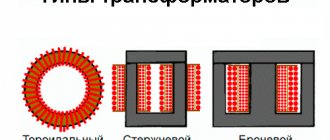
In practice, there is a fairly wide variety of electrical energy converters, both in terms of design features and operating principles. Among the devices for changing the voltage, there are armored, rod and toroidal transformers. The latter option is shaped like a donut, making it the most effective in terms of magnetic flux transmission. Its efficiency can approach 100% and is quite easy to wind, so many radio amateurs try to make a toroidal transformer with their own hands.
Design and operating principle
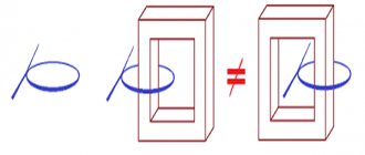
The design feature of such a transformer lies in the shape of the magnetic circuit, which represents a closed ring, called a torus.
Otherwise, the composition of its elements is identical to other types of electrical machines:
- Winding - made with a copper conductor, divided into primary and secondary. Both windings may differ in conductor cross-section.
- Toroidal core - has the shape of a ring, is made by typesetting, strip steel or monolithic iron, depending on the dimensions and purpose. The material used is ferromagnetic alloys, which provide good magnetic conductivity.
- Insulating materials - part of the dielectric is pre-applied to the installation wires, the rest of the dielectric is separated by the torus coil with the iron, the windings among themselves, between the coils and the casing. Tape or varnished fabric materials, electrical insulating cardboard, glue, etc. are used as insulation.
- Protective casing - designed both to protect the power transformer from mechanical damage and to prevent human contact with the surface of the windings.
- Conclusions of the secondary and network windings , fasteners and auxiliary parts.
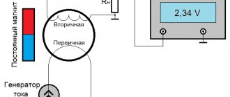
Rice.
1. Design of a toroidal transformer The principle of operation of a toroidal transformer is to supply voltage to the terminals of the primary winding. After which an electric current begins to flow in it, which creates a magnetic flux inside the turns. The magnetic flux moves inside the coil frames and induces an emf in the secondary winding. If a load is connected to its terminals, the specified power will be consumed.
This device has found application in toroidal autotransformers (LATRs), radio electronics, welding transformers and other converters. At home, they rewind this type of transformer through a relatively simple process.
How to simplify the task of winding turns on a core
Knowing how to create a transformer in all details and with all the data, all that remains is to move on to practical work, but winding turns is a rather labor-intensive process that requires special concentration. The correctness of winding is also important and directly affects the characteristics of the resulting device.
But for such cases, there is a special device to help people, a machine for winding toroidal transformers, the price of such a device is not high, but it is not easy to buy, so home-made devices are often found on the market, and if you read the relevant literature, you can try to make this machine yourself .
Source
DIY making
To make a toroidal electric machine, you need to decide on its type. In total, there are step-up and step-down transformers, in the first case, from low voltage, for example, 220V, you get high - 600V, and in the second, from high voltage, low, as the most common option, from 220V - 12V. An important parameter for the manufacture and calculation of a toroidal unit is the transformation ratio, which shows how many times the electrical quantity changes in the secondary winding in relation to the primary. To determine it, one of the following relationships is used:
U1/U2 = W1/W2 = I2/I1 = n
U1 and U2, I1 and I2 are the magnitude of voltage and current in the windings, W1 and W2 are the number of turns.
What is needed for the job?
You will definitely need a set of plumbing tools for basic work: screwdrivers, pliers, pliers, knives, soldering iron, riveter, etc. Also, in order to wind a toroidal network transformer or a homemade welding unit, you will need some materials:
- Copper wire with varnish coating - you can take it with vinyl insulation, but it will be thicker. As a result, winding will require a lot of effort, which is not very convenient with a large number of turns.
- Winding device - most often either an automated ring release mechanism or a shuttle reel is used. The first allows you to wind wires quickly and without extra effort, but purchasing it or making it yourself requires additional costs. The second method is much simpler, but it is less applicable for large cross-section conductors.
- Insulating material - you will need electrical insulating cardboard, polymer dielectric, varnished fabric insulation, fabric insulating tape. To rewind a transformer, you can not use all of the above materials, but select some of them.
- Magnetic core or torus - the best option would be a ready-made factory round core from another transformer. However, if it is not there, you can assemble the toroidal structure yourself. For this purpose, mixing from a core magnetic circuit is suitable.
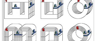
Take a long sheet of steel and bend it into a ring, fixing the ends at the edge.
Rice. 2. Bend the iron plate
Place the next one inside the resulting toroidal sheet, making sure that the edges lie end to end. If necessary, the edges can be trimmed, which is especially important on the inner layers. Each plate must be clearly crimped so that when wound, the torus is tight without gaps.
If you decide to make a core, its edges should be treated with epoxy glue on both sides. After this, the core assembly can be considered complete. In addition, you can use strip steel, which is twisted tightly in a spiral using the same technology.
Rice. 3. Wind the strip steel core
Calculation
To start calculations, you need to decide on the voltage on the secondary and primary windings and the required power of the toroidal transformer. Next you will need to determine the cross section of the torus:
S = H * ((Dd))/2
Where
- S – cross-sectional area of the magnetic circuit;
- H – height of the toroidal core;
- D – outer diameter of the toroidal core;
- d – internal diameter of the toroidal core.
To calculate the number of turns, use two expressions for the transmission coefficient of the magnetic circuit:
k = f/S and W1= k*U1
Here k is the transmission coefficient, f is the frequency in the connected network, S is the cross-sectional area of the magnetic core. W1 is the number of turns in the primary coil, U1 is the voltage in the primary. From the second formula you will find out the number of turns; the turns for the secondary winding of a toroidal transformer are calculated in a similar way.
To determine the wire cross-section of the converter coils, use the formula:
S = (ρ*l * P)/U2
- S – cross-sectional area of the transformer conductor;
- P – power of the toroidal transformer;
- ρ – specific conductivity of the core material (for copper 0.017 Ohm*mm2/m);
- U – voltage in the corresponding winding of the transformer;
- l is the length of the conductor in the coil, this parameter can be found from the following formula:
l = (2 * (Dd) + 2*H)*W
Both the length and cross-section of the transformer can be calculated for each winding separately. After the calculation of the toroidal unit is ready, you can proceed to its winding.
Winding
The process of making a homemade transformer will consist of several stages:
- inspect the toroidal magnetic circuit for the absence of burrs and irregularities - the surface should be smooth, without protruding edges.
Rice. 4. Inspect the core
- make insulation from electrical cardboard for the plates of a homemade transformer; if it is not available, you can take any other dielectric;
Figure 5: Insulate the core with cardboard
- to avoid damaging the wire insulation, place a vinyl tube on the edge of the shuttle and wind the copper wire;
Rice. 6. Vinyl insulation on the edge of the shuttle
- solder the edge of the wire to the first terminal of the winding of the toroidal transformer;
Rice. 7. Solder the wire to the transformer terminal
- insulate with electrical insulating cardboard and secure the soldering area to the core;
Rice. 8. Secure the soldering point to the core
- use a shuttle to wind the winding, while trying to make turns as close to the core as possible;
Rice. 9. Wind the winding with a shuttle
- insulate the primary winding of the toroidal transformer.
Rice.
10. Insulate the primary winding Rewinding the secondary winding is carried out in a similar way, after which it is also insulated and the entire structure, if necessary, is covered with a housing. The toroidal transformer is ready.
Calculation of a toroidal transformer for welding
Calculation of a welding transformer on a toroidal core
The transformer is the main component of the welding machine, regardless of its design. When making this element yourself, many questions arise: How to choose the shape of the magnetic circuit? What kind of winding wire is required? How to calculate the required number of turns?
A toroidal transformer has a number of advantages over other types of transformers:
- Uniform distribution of windings;
- Weight reduction by 20...30% while maintaining power;
- Reduced currents H.H. 10...20 times;
- High efficiency;
- Reducing stray fields;
- Low noise level.
If you put some effort into creating a toroidal transformer with your own hands, you can get your own unique set of device characteristics that will satisfy all your needs when working with welding. And even more than that, you can take into account the current realities of our reality, such as, for example, low voltage in the network of your home.
Using the formulas and methods given in our article, you will receive a practical guide to calculating a welding transformer on a toroidal core.
Calculation method - step-by-step instructions
The calculation of the toroidal transformer itself is divided into two parts:
- You can directly calculate the power of a toroidal core in order to determine it; if you have a specific core, or a given power, then determine the dimensions of the future transformer.
- Calculation of the electrical part itself, which includes the number of turns in the windings, as well as what cross-section will be used in the windings and wire material.
Core calculation
We will produce it using a formula that already includes constants to simplify the understanding of its results. Next, all that remains is to substitute only variable values into the formula below, namely:
We recommend! How to make welding electrodes with your own hands
“P=1.9*Sc*So” , where:
- P is the power that can be obtained using a core with such overall dimensions
- 1.9 - the result of mathematical operations on all constants for this type of transformers
- Sc - core area, unit of measurement square centimeters
- So is the area of the hole in the core body, in “sq. cm."
Formulas for calculating the cross-sectional area of a toroidal core
If the transformer made will have the main purpose of welding, then the dimensions of its core must be adequate, otherwise the resulting power of the device will not be enough to perform its functions. For example, take the following values and use a calculator to calculate. "P=1.9*70*70=9310 Watt"
Let's determine the number of turns of the primary winding
First of all, we will consider the calculation with a single primary winding, without adjustment. To do this, we first find out how many winding turns a toroidal transformer must have to produce 1 volt of voltage. Let's apply the following formula. K=35/Sc , where:
- K is the number of turns per 1 volt of voltage.
- 35 is a constant that is the same for all types of toroidal cores.
- Sc is the area of the core, the unit of measurement is square centimeters.
Thus, if we have a core with an area of 70 "sq. see", then substituting the values in the formula, we get the following situation. “K=35/70=0.5” turns for each volt, and accordingly we find out the volume of the primary winding by applying the appropriate formula. “W1=U1*K” , where:
- W1 is the number of turns in the first winding.
- U1 is the required voltage at this point.
- K is the number of turns per 1 volt of voltage.
Main advantages
In such a transformer, the magnetic circuit has the shape of a toroid, in other words, all the rings have a rectangular cross-section. Unique performance characteristics are highly valued in both domestic and industrial areas. In addition, the toroidal unit has a number of additional advantages in contrast to standard rod and armored models:
- Craftsmen now have an excellent opportunity to use steel with increased magnetic permeability (E-370, 340) for the core.
- It is known that the final leakage flux in an ideal toroidal coil should be equal to zero. In such a transformer this indicator has a certain finite value. But such leakage fluxes are not as large as those of conventional models, so external magnetic fields do not affect the smooth operation of the transformer.
- There are absolutely no gaps or joints in the core.
- The master can safely use the structural properties of the core, since in a toroidal unit the direction of the magnetic field completely coincides with the rolling of the tape.
All of the above advantages allow us to achieve high economic and electrical performance. Due to this, equipment productivity increases significantly:
- The total number of turns that are used to obtain the value of the inductive primary winding is significantly reduced. This effect is achieved through the use of steels with high magnetic permeability. In some designs, craftsmen managed to reduce the final copper consumption by 25%.
- The complete absence of gaps and the presence of high-alloy steel is the reason that higher induction is achieved in the transformer core. This functional advantage does not affect the total harmonic distortion factor at all. As a result, the master manages to double Bmax, which is considered impossible in armored transformers. As a result, the final weight and volume of the working core is reduced.
- A uniform frequency response of the cascade is achieved due to the small amount of leakage inductance. The presence of minimal distortion due to transient processes allows the use of fairly deep feedback of a negative type.
Due to the fact that the toroidal transformer has a small magnetic field, even the closest installation does not affect the interaction with other structural elements.
Calculation of a transformer with a toroidal magnetic core :: AutoMotoGarage
There was a need for a powerful power supply. In my case, there are two magnetic cores: armored tape and toroidal. Armor type: ШЛ32х50(72х18). Toroidal type: OL70/110-60.
INITIAL DATA for calculating a transformer with a toroidal magnetic core:
- primary winding voltage, U1 = 220 V;
- secondary winding voltage, U2 = 36 V;
- secondary winding current, l2 = 4 A;
- core outer diameter, D = 110 mm;
- core inner diameter, d = 68 mm;
- core height, h = 60 mm.
Calculation of a transformer with a magnetic core type ШЛ32х50 (72х18) showed that the core itself is capable of producing a voltage of 36 volts with a current strength of 4 amperes, but it may not be possible to wind the secondary winding due to insufficient window area.
Let's start calculating a transformer with a magnetic core of type OL70/110-60.
Software (on-line) calculation will allow you to experiment with parameters on the fly and reduce development time. You can also calculate using the formulas, they are given below.
Description of the input and calculated fields of the program: a light blue field - the initial data for calculation, a yellow field - data selected automatically from the tables, if you check the box to adjust these values, the field changes color to light blue and allows you to enter your own values, green field – calculated value.
Formulas and tables for manual calculation of a transformer:
1. Secondary winding power;
2. Overall power of the transformer;
Table No. 1.
Value Total power of secondary windings Pout, [W]2-15 15-50 50-150 150-300 300-1000
| Compared to conventional designs, toroidal transformers have a number of significant advantages. Despite their small size and weight, they have a significantly higher efficiency. Therefore, these devices are widely used in welding machines and voltage stabilizers. The correct calculation of a toroidal transformer in relation to specific operating conditions is of great importance. There are various calculation methods that provide results with varying degrees of accuracy. Most often, tables are used for calculations. Definition of basic parametersBefore starting calculations, it is necessary to determine the basic parameters of the transformer. First of all, this concerns the type of wires and the number of turns, on which the total length of the conductor depends. Next, you need to make the right choice of cross-section, which affects the output current and power of the device. One should also take into account the fact that with a small number of turns, the primary winding will heat up. Exactly the same situation arises when the power of consumers connected to the secondary winding exceeds the power supplied by the transformer. As a result of overheating, the reliability of the device decreases, and sometimes the transformer may ignite. As an example, a table is given that can be used to calculate a toroidal transformer operating at a network frequency of 50 Hz. The cores of the devices can be made of cold-rolled steel grades E310-330, with a thickness of 0.35 to 0.5 mm. Ordinary steel, grades E340-360, can also be used, where the thickness of the tape will be in the range from 0.05 to 0.1 mm. The symbols in the table correspond to:
When winding a toroidal coil, only external and interwinding insulation is used. Despite the even laying of the winding wires, the winding thickness along the inner diameter necessarily increases due to the difference between the outer and inner diameters of the core. Therefore, it is recommended to use conductors whose insulation has increased mechanical and electrical strength, for example, PELSHO and PESHO brands, and in some cases - PEV-2. For external and inter-winding insulation, cambric tape, LShSS varnished fabric, 0.06-0.12 mm thick, as well as triacetate or fluoroplastic film, 0.01-0.02 mm thick, are most often used. Formulas for calculating a toroidal transformerThe main parameters for calculating a toroidal transformer are the power supply voltage (Uc) equal to 220 V, the output voltage value (Un) - 24 V, current load (In) - 1.8 A. To determine the power of the secondary winding there is a formula: P = U n x I n = 24 x 1.8 = 43.2 W. Next, the overall power of the transformer device is determined by the formula: The efficiency value and other data necessary for calculations are selected from the table in the appropriate column and row for a specific overall power. The next step is to calculate the cross-sectional area of the core using the formula: The selection of core sizes is carried out as follows: The closest type of core with standard parameters will be OL50/80-40, with a cross-sectional area S = 60 mm2, which should be no less than the design one. The inner diameter of the core is determined in accordance with the condition that dc has a value greater than or equal to dc':
Now you need to determine the number of turns in the primary and secondary windings: Since magnetic flux dissipation in any toroid is very insignificant, the voltage drop in the windings can only be determined by their active resistance. As a result, the relative value of the voltage drop in the windings of a toroidal transformer will be much less than in conventional transformers. In this regard, losses in the resistance of the secondary winding are compensated by increasing the number of turns by approximately 3%. The calculation will look like this: W1-2=133 x 1.03=137 turns. The diameters of the winding wires can be determined by the formula:
The diameter of the wire is selected according to the nearest value upward, which will be 0.31 mm. Transformers manufactured according to calculations using the table have been successfully tested at a constant maximum load operating for several hours. Thus, the calculation of a toroidal transformer allows one to obtain accurate results confirmed in practice. Using this technique, you can determine the necessary parameters for any device. | ||||
| Efficiency | 0,76-0,88 | 0,88-0,92 | 0,92-0,95 | 0,95-0,96 |
3. The actual cross-section of the steel of the magnetic core at the location of the transformer coil;
4. The calculated cross-section of the magnetic core steel at the location of the transformer coil;
5. Actual cross-sectional area of the core window;
6. The value of the rated current of the primary winding;
Table No. 2.
Value Total power of secondary windings Pout, [W]2-15 15-50 50-150 150-300 300-1000
| COS Φ | 0,85-0,90 | 0,90-0,93 | 0,93-0,95 | 0,95-0,93 | 0,93-0,94 |
7. Calculation of the wire cross-section for each of the windings (for I1 and I2);
Table No. 3.
Magnetic circuit design Current density J, [A/mm sq.] at Pout, [W]2-15 15-50 50-150 150-300 300-1000
| Ring | 5-4,5 | 4,5-3,5 | 3,5 | 3,0 |
8. Calculation of the diameter of the wires in each winding without taking into account the thickness of the insulation;
9. Calculation of the number of turns in the transformer windings;
n – winding number, U' – voltage drop in the windings, expressed as a percentage of the nominal value, see table.
In toroidal transformers, the relative value of the total voltage drop in the windings is significantly less compared to armored transformers.
Table No. 4.
Tor, value U' Total power of secondary windings Pout, [W]8-25 25-60 60-125 125-250 250-600
| U'1 | 7 | 6 | 5 | 3.5 | 2.5 |
| U'2 | 7 | 6 | 5 | 3.5 | 2.5 |
Table No. 5.
Magnetic circuit design Magnetic induction Vmax, [T] at Pout, [W] 5-15 15-50 50-150 150-300 300-1000
| Thor | 1,7 | 1,7 | 1,7 | 1,65 | 1,6 |
10. Calculation of the number of turns per volt;
11. Formula for calculating the maximum power that the magnetic circuit can deliver;
Sst f – the actual cross-section of the steel of the existing magnetic circuit at the location of the coil;
Sok f – actual window area in the existing magnetic circuit;
Vmax - magnetic induction, see table No. 5;
J – current density, see table No. 3;
Kok – window fill factor, see table No. 6;
Kst – coefficient of filling of the magnetic circuit with steel, see table No. 7;
The magnitudes of electromagnetic loads Vmax and J depend on the power removed from the secondary winding of the transformer circuit and are taken for calculations from tables.
Table No. 6.
Magnetic circuit design Window filling factor Coc at Pout, [W] 5-15 15-50 50-150 150-300 300-1000
| Thor | 0,18-0,20 | 0,20-0,26 | 0,26-0,27 | 0,27-0,28 |
Table No. 7.
Magnetic core design Filling factor Kst with steel thickness, mm0.08 0.1 0.15 0.2 0.35
| Thor | 0,85 | 0,88 |
Having determined the value of Sst*Sok, you can select the required linear size of the magnetic circuit, having an area ratio no less than that obtained as a result of the calculation.
There was a need for a powerful power supply. In my case, there are two magnetic cores: armored tape and toroidal. Armor type: ШЛ32х50(72х18). Toroidal type: OL70/110-60.
Short description
Modern manufacturers are engaged in the industrial production of several types of magnetic cores for transformers - armored, rod, toroidal. If we compare their operational characteristics and areas of use, then the latter option can be considered more effective. The thing is that such a device has extremely positive parameters , due to which it is actively used in modern industry.
High performance and long service life have led to the fact that now the toroidal transformer is a basic element in lighting technology, voltage stabilizers, uninterruptible power supplies, radio engineering, as well as medical and diagnostic equipment.
The manufacturers themselves claim that such a unit is presented in the form of a single-phase installation, which can both reduce and increase power. For high-quality operation, the transformer is equipped with a powerful core with two or more windings. But the principle of its operation is no different from those models that are equipped with armor or rod winding.
Regardless of its operational characteristics, a transformer is a device whose main task is based on converting electricity from one quantity to another. However, even the most minimal changes in design can significantly change the final size and weight of the electrical installation. Thanks to this, technical and economic parameters will only increase.
How can I determine the current density?
If we are making a low-power transformer, we can play with the current density and choose thinner wires without fear of overheating. In Eranosyan’s book the following tablet is given:
Why does current density depend on the power of the transformer? The amount of heat released is equal to the product of the specific losses and the volume of the wire. The dissipated amount of heat is proportional to the area of the winding and the temperature difference between it and the environment. As the size of the transformer increases, the volume grows faster than the area, and for the same overheating, the specific losses and current density must be reduced. For transformers with a power of 4..5 kVA, the current density does not exceed 1..2 A/mm 2.
Resistance of a circuit of parallel connected resistors:
A program for calculating the resistance of a circuit composed of resistors connected in parallel. A special feature of the program is the ability to interactively add resistance to a parallel connection to instantly obtain the value of the total resistance of the circuit. There are no restrictions or presets on the number of elements connected in parallel. Works in DOS and Windows 97/XP/7 (32-bit) - in a command line session. The program is free. To calculate, unpack the archive, click on the program file with the mouse and follow the instructions in Russian. The program does not need to be installed and works from any media.
Download free program for DOS/Windows 32-bit archive .zip 22.3 kb
For Windows 7 - 64 bit(132 kb)
For Linux - zip 488 kb Note about running the program for Linux:
To run, unpack the parsop file into the /bin directory or /usr/local/bin , assign it 777 rights with the command #chmod 777 /bin/paralsop or #chmod 777 /usr/local/bin/paralsopthen you can run the program with the command: $paralsop in the first option or $/usr/local/bin/paralsop in the second option
Online calculation of a circuit of parallel connected resistors