Energy losses in any case, regardless of the type of production, cause cost and material overruns. It is for this reason that the cost of energy may increase. Therefore, the fight against this factor plays a very important role. This procedure is based on carrying out equipment maintenance, thanks to which it is possible to identify any problems that have arisen, which is important for the timely implementation of preventive measures to eliminate the likelihood of failures in functionality. Transformer no-load losses are one of the most common problems.
Transformer no-load concept
When a transformer has a dedicated power supply to one winding, while the others are in an open state. This process leads to energy leakage, which is called no-load losses. Its development occurs under the influence of a number of external and internal factors.
The power of the transformer is not fully used, and part of the energy is lost due to some magnetic processes, features of the primary winding and insulating layer. The latter option affects when using devices operating at a higher frequency.
Rules for assembling transformers and methods for reducing winding losses
Since its operating parameters and operating features depend on the correct assembly of the equipment, installation personnel must remember their responsibility. Even the number of materials used when installing the transformer depends on the professionalism of the assemblers.
Modern transformer equipment is made from elements that do not have reliable protection against mechanical damage. Because of this feature, even one incorrect action by the installer can lead to a decrease in the magnetic properties of the metal. Any mechanical damage to the transformer will lead to a decrease in the functionality of the device, its efficiency and reliability.
The main losses of electrical energy occur on the windings of transformer equipment, and, in most cases, due to the load current. The load, and therefore losses, can be reduced by increasing the cross-sectional diameter of the cable used in the winding. This technique is considered the most effective, but not entirely cost-effective, since increasing the diameter of the winding cable may lead to the need to increase other characteristics of the device, which will require significant funding.
A more correct and cheaper option for reducing losses and increasing the profitability of equipment is to control the symmetry of the installed windings. Specialists should be aware that even a slight difference in the parameters of the windings can lead to an increase in electricity losses. Losses due to differences in windings can also lead to strong heating of individual elements of the installation.
Below you can use the online calculator to calculate the cost of electrical laboratory services.
What factors influence losses
Modern transformers reach 99% efficiency under full load conditions. But devices continue to be improved, trying to reduce energy loss, which is almost equal to the sum of idle losses arising under the influence of various factors.
Insulation
If the tie rods have poor or insufficient insulation, a short-circuit will occur. This is one of the main factors for this transformer problem. Therefore, more attention should be paid to the insulation process, using high-quality specialized materials for these purposes.
Eddy currents
The development of eddy currents is associated with the flow of magnetic flux along the magnetic circuit. Their feature is perpendicular to the flow. To reduce them, the magnetic circuit is made of separate elements, pre-insulated. The probability of the occurrence of eddy currents depends on the thickness of the sheet; the smaller it is, the lower the risk of their development, leading to lower power losses.
To reduce eddy currents and increase the electrical resistance of steel, various types of additives are added to the material.
They improve the properties of the material and reduce the risk of developing unfavorable processes that adversely affect the operation of the device.
Hysteresis
Like alternating current, magnetic flux also changes its direction. This indicates alternate magnetization and remagnetization of steel. When the current changes from maximum to zero, the steel demagnetizes and the magnetic induction decreases, but with a certain delay.
When the direction of the current changes, the magnetization curve forms a hysteresis loop. It differs in different grades of steel and depends on what maximum magnetic induction values the material can withstand. The loop covers power, which is gradually overspent on the magnetization process. In this case, the steel is heated, the energy conducted through the transformer is converted into heat and dissipated into the environment, that is, it is wasted, without bringing any benefit to all users.
Characteristics of electrical steel
For transformers, cold-rolled steel is mainly used. But the loss rate in it depends on how well the device was assembled and whether all rules were followed during the production process.
To reduce losses, you can also slightly increase the cross-section of the wires on the winding. But this is not profitable from a financial point of view, because you will have to use more magnetic circuit and other important materials. Therefore, the size of the winding wires is rarely changed. They are trying to find another, more economical way to solve this problem.
Overheat
During operation of the transformer, its elements may heat up. Under these conditions, the device is not able to perform its functions normally. It all depends on the speed of this process. The higher the heating, the faster the device will stop performing its direct functions and will require major repairs and replacement of certain parts.
In the primary winding
If the electric current through the conductor is short-circuited, then there is a high probability of electrical energy leakage. The size of the losses depends on the magnitude of the current in the conductor and its resistance, as well as on the loads placed on the device.
What do losses affect and what do they depend on?
During the transportation of electrical energy from production facilities to the final consumer, serious losses occur. The volume of losses during transportation can be up to 18%, and most of these losses occur in transformer equipment.
The volume of losses must be taken into account by designers when creating electrical consumption systems. The cost of electrical energy, the cost of maintenance and repair of electrical equipment will depend on the losses.
Until the mid-20th century, hot-rolled steel was used for the production of transformers, which had low technical characteristics. In the 50s of the last century, such steel began to be gradually replaced by cold-rolled metal with a grain structure. The main advantage of more modern steel was a higher level of magnetic permeability, and therefore greater efficiency of transformer equipment in general.
From then to the present day, cold-rolled steel production technologies have been constantly improved, and today the parameters of such materials have improved even further.
Currently, the level of no-load losses of transformer equipment has been significantly reduced due to the use of more modern and functional steel, improved design of magnetic systems and modernization of cores.
If we consider the features of modern steel used to create plates, its positive properties are associated with the fact that over time, manufacturers have improved the orientation of domains and reduced the thickness of steel sheets during production. In addition, domain cleaning today is carried out through laser processing, which also affects the technical characteristics of the final products. Specialists involved in measuring and selecting transformer equipment should know the differences between transformers and autotransformers.
Table of losses of power transformers according to reference data depending on the rating
Most often, the problem of electricity leakage is associated with the movement of eddy currents and magnetization reversal. Under the influence of these factors, the magnetic circuit heats up, which causes the bulk of no-load losses, regardless of the load current. The development of this process occurs regardless of the mode in which the device operates.
Gradually, under the influence of certain factors, these indicators may change towards a significant increase.
Loss table XX
| Power kVA | HV/LV voltage, kV | No-load losses W |
| 250 | 10/0,4 | 730 |
| 315 | 10/0,4 | 360 |
| 400 | 10/0,4 | 1000 |
| 500 | 10/0,4 | 1150 |
| 630 | 10/0,4 | 1400 |
| 800 | 10/0,4 | 1800 |
| 1000 | 10/0,4 | 1950 |
Checking the device in XX mode
To do this, perform the following actions:
- Using a voltmeter, check the voltage supplied to the coil.
- Use another voltmeter to examine the voltage at the remaining terminals. It is important to use a device with sufficient resistance so that the readings are of the required value.
- Connect the ammeter to the primary winding circuit. With its help, you can determine the strength of the no-load current. They also resort to using a wattmeter, with which they try to measure the power level.
After receiving readings from all instruments, calculations are performed that will help in the calculation. To obtain the necessary data, it is necessary to divide the indicators of the first winding by the second. Using the data from the XX experiment with the results of the short-circuit mode, it is determined how fully the device performs its actions.
What does transformer testing include?
The first professional electrical measurements involve several separate tests and studies, each of which provides accurate information about the functionality of the transformer device.
In addition to measuring losses in no-load mode, electrical laboratory specialists will also need to determine the transformation ratio of the device, check the quality of insulation, the quality of the connection of the windings and the resistance parameters on the windings of the transformer. When conducting a transformer study, you should not only correctly perform all stages of electrical measuring work, but also carry them out in the correct sequence. Any errors in power supply projects can cause failure of transformer equipment.
At the first stage of measurement work, specialists will need to measure the current characteristics during idle operation of the device. In accordance with modern laws, only qualified specialists with an electrical safety level of at least 3 are allowed to measure the no-load speed of a transformer device. Each electrical laboratory employee is required to use personal protective equipment and work in accordance with all safety standards.
To obtain accurate information about the no-load current, work must be carried out at a voltage from 220 V to 380 V. The voltage can be applied exclusively to the winding of transformer equipment, and the voltage level must be constantly monitored by team members using professional measuring instruments.
Since after disconnecting the device, residual magnetization may remain on the magnetic circuit, electrical laboratory specialists will need to demagnetize it. To do this, craftsmen need to pass a current of opposite polarity through the winding. Modern portable batteries are usually used for this work. If a three-phase device is being examined, then measurements must be carried out phase by phase, due to which it will be possible to identify the faulty conductor and compare the operating characteristics of the device with factory parameters.
To obtain current current characteristics, specialists will need to short-circuit one of the phases of the device one by one, checking the remaining conductors.
Features of the XX mode in a three-phase transformer
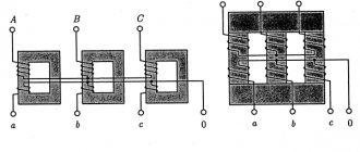
The operation of a three-phase transformer in this mode is affected by differences in the connection of the windings: the primary coil is in the shape of a triangle and the secondary coil is in the shape of a star. The current helps create its own flow.
Three-phase current in the form of a group of single-phase ones has the following features: the closure of the TGS magnetic flux occurs in each phase due to the core. If the voltage gradually increases, a breakdown will occur in the insulation and the electrical installation will sooner or later fail.
If a transformer uses an armored rod magnetic system, then the development of similar processes can be observed in it.
Conclusion
Energy losses during no-load conditions of the transformer are associated with magnetic losses, losses in the primary winding and insulating layer. Work is still underway to reduce this indicator, despite the fact that the efficiency of modern transformers under high load conditions is 99%.
To reduce the rate of energy leakage, it is necessary to reduce the influence of provoking factors. To achieve this, they are constantly improving the technology for creating devices, using only durable materials, testing them experimentally.
Operating modes of transformer devices
At the moment, there are about ten types of different transformer devices. All of them are united by a single principle of changing alternating voltage and structural similarity. Accordingly, each of the transformers is capable of operating in three main modes: no-load, short circuit and load. The idle mode allows you to make a number of measurements, the data of which is necessary for a comprehensive analysis of the efficiency of the devices. The first tests are carried out to determine and verify compliance with the passport values of the technical data of the transformer as a whole and each of its components in particular before putting the device into operation. Commissioning works reveal hidden faults and allow them to be corrected before intensive use of the device. Some of them are carried out at the assembly stage, and some are carried out after the oil has been poured.