Sections of the site
DirectAdvert NEWS
friends of site
Action Teaser NEWS
Statistics
The magnetic core of the low-frequency transformer consists of steel plates. Using laminations instead of a solid core reduces eddy currents, which increases efficiency and reduces heat.
Magnetic cores of type 1, 2 or 3 are produced by stamping. Magnetic cores of types 4, 5 or 6 are produced by winding a steel tape onto a template, and magnetic cores of types 4 and 5 are then cut in half.
1, 4 – armored, 2, 5 – rod, 6, 7 – ring.
To determine the cross-section of the magnetic circuit, you need to multiply the dimensions “A” and “B”. For calculations in this article, the section size in centimeters is used.
Transformers with twisted rod position 1 and armored magnetic cores position 2.
Transformers with stamped armored magnetic cores, position 1, and core magnetic cores, position 2.
Transformers with twisted ring magnetic cores.
The overall power of a transformer can be approximately determined by the cross-section of the magnetic core. True, the error can be up to 50%, and this is due to a number of factors. The overall power directly depends on the design features of the magnetic core, the quality and thickness of the steel used, the size of the window, the amount of induction, the cross-section of the winding wire and even the quality of the insulation between the individual plates.
The cheaper the transformer, the lower its relative overall power. Of course, it is possible through experiments and calculations to determine the maximum power of a transformer with high accuracy, but there is not much point in this, since during the manufacture of the transformer, all this is already taken into account and reflected in the number of turns of the primary winding. So, when determining the power, you can be guided by the cross-sectional area of the set of plates passing through the frame or frames, if there are two of them.
Where:
P
– power in Watts,
B
– induction in Tesla,
S
– cross section in cm²,
1.69
– constant coefficient.
First, we determine the cross-section, for which we multiply the dimensions A and B.
Then we substitute the cross-sectional size into the formula and get the power. I chose 1.5Tc induction, since I have an armored twisted magnetic circuit.
If you need to determine the required cross-sectional area of the manipulator based on the known power, you can use the following formula:
It is necessary to calculate the cross-section of an armored stamped magnetic circuit for the manufacture of a 50-watt transformer.
The magnitude of induction can be found in the table. You should not use maximum induction values, as they can vary greatly for magnetic cores of different quality.
Maximum indicative values of induction.
HOW TO CALCULATE A STEP-DOWN TRANSFORMER.
In a household, it may be necessary to equip lighting in damp areas: basement or cellar, etc. These rooms have an increased risk of electric shock.
In these cases, you should use electrical equipment designed for a reduced supply voltage, no more than 42 volts. You can use a battery-powered electric flashlight or use a step-down transformer from 220 volts to 36 volts.
As an example, let's calculate and manufacture a single-phase 220/36 volt power transformer. To illuminate such rooms, a 36-volt electric light bulb with a power of 25-60 watts is suitable. Such light bulbs with a base for a standard socket are sold in electrical goods stores.
If you find a light bulb of a different power, for example 40 watts, there is nothing to worry about - that will do. It’s just that our transformer will be made with a power reserve.
Power in the secondary circuit: P2 = U2 • I2 = 60 watts
Where:
P2
is the power at the output of the transformer, we set 60 watts;
U2
is the voltage at the transformer output, we set it to 36 volts;
I2
is the current in the secondary circuit, in the load.
Transformer efficiency up to 100 watts
usually equal to no more than
η = 0.8
. Efficiency determines how much of the power consumed from the network goes to the load. The remainder goes to heating the wires and core. This power is irretrievably lost.
Let's determine the power consumed by the transformer from the network, taking into account losses:
Power is transferred from the primary winding to the secondary winding through the magnetic flux in the magnetic core. Therefore, the cross-sectional area of the magnetic circuit S depends on the value of P1, the power consumed from the 220 volt network.
The magnetic core is a W-shaped or O-shaped core made from sheets of transformer steel. The core will contain a frame with primary and secondary windings.
The cross-sectional area of the magnetic circuit is calculated by the formula:
Where:
S
is the area in square centimeters,
P1
is the power of the primary network in watts.
The value of
S
is used to determine the number of turns w per volt using the formula:
In our case, the cross-sectional area of the core is S = 10.4 cm2.
Let's calculate the number of turns in the primary and secondary windings.
Number of turns in the primary winding at 220 volts:
Number of turns in the secondary winding at 36 volts:
In load mode, there may be a noticeable loss of part of the voltage across the active resistance of the secondary winding wire. Therefore, for them it is recommended to take the number of turns 5-10% more than calculated. Let's take W2 = 180 turns.
The magnitude of the current in the primary winding of the transformer:
Current in the secondary winding of the transformer:
The diameters of the wires of the primary and secondary windings are determined by the values of the currents in them based on the permissible current density, the number of amperes per 1 square millimeter of conductor area. For transformers, the current density for copper wire is assumed to be 2 A/mm².
Read also: Brinell hardness tester
At this current density, the diameter of the wire without insulation in millimeters is determined by the formula:
For the primary winding, the wire diameter will be:
Wire diameter for secondary winding:
IF THERE IS NO WIRE OF THE REQUIRED DIAMETER, then you can take several thinner wires connected in parallel. Their total cross-sectional area must be no less than that corresponding to the calculated one wire.
The cross-sectional area of the wire is determined by the formula:
Where:
d is the diameter of the wire.
For example:
we could not find a wire for the secondary winding with a diameter of 1.1 mm.
The cross-sectional area of a wire with a diameter of 1.1 mm is equal to:
Let's round up to 1.0 mm².
From the table we select the diameters of two wires, the sum of the cross-sectional areas of which is equal to 1.0 mm².
For example, these are two wires with a diameter of 0.8 mm. and an area of 0.5 mm².
Or two wires:
- the first with a diameter of 1.0 mm. and a cross-sectional area of 0.79 mm², - the second with a diameter of 0.5 mm. and a cross-sectional area of 0.196 mm². which adds up to: 0.79 + 0.196 = 0.986 mm².
The coil is wound with two wires simultaneously; an equal number of turns of both wires is strictly maintained. The beginnings of these wires are connected to each other. The ends of these wires are also connected. It turns out like one wire with the total cross-section of two wires.
A power transformer is the simplest example of electrical energy conversion. Even with the constant improvement of radio-electronic devices and power supplies based on them, power supplies based on alternating voltage transformers do not lose their relevance.
Transformers for the power supply are large in size and weight, operate within a limited range of permissible input voltage, but are very easy to implement and are highly reliable and maintainable.
General information about transformers
A transformer is an electromagnetic device that converts alternating current with a change in voltage value.
The operating principle of the device involves the use of electromagnetic induction. The device consists of the following main elements:
- primary and secondary windings;
- the core around which the windings are wound.
Transformer operating principle
The change in characteristics is achieved due to different numbers of turns in the input and output windings.
The current in the output coil is excited by the creation of magnetic flux when voltage is applied to the input contacts.
Transformer design
If you look at the transformer from the outside, it is an W-shaped device consisting of a metal core, a cardboard or plastic frame and a copper wire winding. There are two windings.
The core is several steel plates that are treated with a special varnish and connected to each other. The varnish is applied specifically to prevent tension from passing between the plates. In this way they fight the so-called eddy currents (Foucault currents). The thing is that Foucault currents will simply heat the core itself. And these are losses.
The composition of the core plates is also associated with losses. Transformer iron (as core steel is most often called by experts), if you look at it in cross-section, consists of large crystals, which, in turn, are isolated from each other by an oxide film.
Transformer device
What if the coils are different? Then you can convert the voltage from one value to another. This is how a transformer works. A transformer converts voltage from the primary winding to a different voltage on the secondary winding.
The transformer only works with alternating, pulsed or any other current whose value changes over time.
A transformer converts current and voltage, but it does not allow increasing power. On the contrary, due to heating it takes a little power. And despite this, its efficiency can reach up to 99%.
Purpose and functionality
So, what functions does a transformer perform?
- This is a reduction in voltage to the required parameters.
- With its help, the galvanic isolation of the network is reduced.
As for the second function, it is necessary to give explanations. Both windings (primary and secondary) of the current transformer are not directly connected to each other. This means that the resistance of the device, in fact, should be infinite. True, this is an ideal option. The connection of the windings occurs through the magnetic field created by the primary winding. This is such a complex functionality.
Transformer operating principle
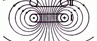
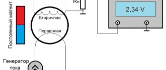
The operating principle of the transformer is based on the phenomenon of electromagnetic induction.
If an alternating voltage U1 is applied to the primary winding, then an alternating current Io will flow through the turns of the winding, which will create an alternating magnetic field around the winding and in the magnetic core. The magnetic field forms a magnetic flux Фo, which, passing through the magnetic circuit, crosses the turns of the primary and secondary windings and induces (induces) alternating emfs in them - e1 and e2. And if a voltmeter is connected to the terminals of the secondary winding, it will show the presence of output voltage U2, which will be approximately equal to the induced emf e2.
When a load, for example an incandescent lamp, is connected to the secondary winding, a current I1 arises in the primary winding, forming an alternating magnetic flux F1 in the magnetic circuit, changing at the same frequency as the current I1. Under the influence of an alternating magnetic flux, a current I2 arises in the secondary winding circuit, which in turn creates a counteracting magnetic flux F2 according to Lenz’s law, tending to demagnetize the magnetic flux generating it.
As a result of the demagnetizing effect of the F2 flux, a magnetic flux Фo is established in the magnetic circuit equal to the difference between the F1 and F2 fluxes and being part of the F1 flux, i.e.
The resulting magnetic flux Фo ensures the transfer of magnetic energy from the primary winding to the secondary winding and induces an electromotive force e2 in the secondary winding, under the influence of which current I2 flows in the secondary circuit. It is due to the presence of magnetic flux Фo that current I2 exists, which will be greater the greater Фo. But at the same time, the greater the current I2, the greater the counteracting flow F2 and, therefore, the less Fo.
From the above it follows that at certain values of the magnetic flux F1 and the resistance of the secondary winding and load, the corresponding values of the emf e2, current I2 and flux F2 are established, ensuring the equilibrium of magnetic fluxes in the magnetic circuit, expressed by the formula given above.
Thus, the difference between the flows Ф1 and Ф2 cannot be equal to zero, since in this case the main flow Фo would be absent, and without it the flow Ф2 and current I2 could not exist. Consequently, the magnetic flux Ф1, created by the primary current I1, is always greater than the magnetic flux Ф2, created by the secondary current I2.
The magnitude of the magnetic flux depends on the current creating it and on the number of turns of the winding through which it passes.
The voltage of the secondary winding depends on the ratio of the number of turns in the windings. With the same number of turns, the voltage on the secondary winding will be approximately equal to the voltage supplied to the primary winding, and such a transformer is called an isolation transformer.
If the secondary winding contains more turns than the primary, then the voltage developed in it will be greater than the voltage supplied to the primary winding, and such a transformer is called a step-up transformer.
If the secondary winding contains fewer turns than the primary, then its voltage will be less than the voltage supplied to the primary winding, and such a transformer is called a step-down transformer.
Hence. By selecting the number of turns of the windings, for a given input voltage U1, the desired output voltage U2 is obtained. To do this, they use special methods for calculating the parameters of transformers, with the help of which the windings are calculated, the cross-section of the wires is selected, the number of turns is determined, as well as the thickness and type of the magnetic core.
The transformer can only operate in alternating current circuits. If its primary winding is connected to a direct current source, then a magnetic flux is formed in the magnetic circuit, constant in time, in magnitude and direction. In this case, an alternating voltage will not be induced in the primary and secondary windings, and therefore, electrical energy will not be transferred from the primary circuit to the secondary. However, if a pulsating current flows in the primary winding of the transformer, then an alternating voltage will be induced in the secondary winding, the frequency of which will be equal to the ripple frequency of the current in the primary winding.
We recommend reading: How to measure resistance with a multimeter: instructions, photos, videos
5. Determination of the load for additional windings of voltage transformers
The load on the additional windings of voltage transformers connected in an open delta circuit is determined by the calculated consumption of the relays and devices connected to these windings. The calculation results are compared with the permissible power of the corresponding class of this type of voltage transformer. When connecting only relay equipment to additional windings, it is required to operate in accuracy class 3, and when connecting measuring instruments in accuracy class 0.2; 0.5.
What is the efficiency of a transformer and what does it depend on?
Efficiency (the full interpretation of this abbreviation) is the ratio of useful electricity to that supplied to the device.
In addition to energy, the efficiency indicator can be determined by calculation based on power indicators based on the ratio of the useful value to the total value. This characteristic is very important when choosing a device and determines the effectiveness of its use.
The magnitude of the efficiency depends on the energy losses that are allowed during the operation of the device. These losses are of the following types:
- electrical - in the conductors of the coils;
- magnetic - in the core material.
The magnitude of these losses when designing a device depends on the following factors:
- overall dimensions of the device and shape of the magnetic system;
- compactness of the coils;
- density of assembled sets of plates in the core;
- diameter of wire in coils.
Reducing losses in the unit is achieved during the design process of the device, using soft magnetic ferromagnetic materials for the manufacture of the core. Electrical steel is assembled into thin plates, insulated relative to each other by a special layer of applied varnish.
During operation, the efficiency of the device is determined by:
- applied load;
- dielectric medium - a substance used as a dielectric;
- uniformity of load supply;
- oil temperature in the unit;
- degree of heating of the coils and core.
If during operation the unit is constantly underloaded or the specified operating conditions are violated, in addition to the risk of failure, this leads to a decrease in the efficiency of the device.
Methods for determining efficiency
Transformer efficiency can be calculated using several methods. This value depends on the total power of the device, increasing with the increase in the specified indicator. The efficiency value ranges from 0.8 to 0.92 at power values from 10 to 300 kW.
Knowing the value of the maximum power, you can determine the efficiency value using special tables.
Direct measurement
The formula for calculating this indicator can be presented in several expressions:
ɳ = (Р2/Р1)х100% = (Р1 – ΔР)/Р1х100% = 1 – ΔР/Р1х100%,
- ɳ – efficiency value;
- P2 and P1 – respectively the value of useful and consumed network power;
- ΔР – the value of the total power losses.
From this formula it is clear that the value of the efficiency indicator cannot exceed one.
After a step-by-step transformation of the above formula, taking into account the use of the values of electric current, voltage and angle between the phases, the following relationship is obtained:
ɳ = U2хI2хcosφ2/ U2хI2хcosφ2 + Robm + Рс,
- U2 and I2 – respectively, the value of voltage and current in the secondary winding;
- Robm and Rs - the amount of losses in the windings and core.
The presented formula is contained in GOST, which describes the definition of this indicator.
Efficiency calculations
Determination by indirect method
For devices with high operating efficiency, with an efficiency value exceeding 0.96, accurate calculation is not always possible. Therefore, this value is determined using an indirect method, which involves assessing the power indicators in the primary coil, the secondary coil and the allowed losses.
Assessing the characteristics of the transformer, it should be noted the high efficiency of using this equipment, due to its design features.
What is power factor
Several types of load occur in the alternating current circuit that enters the transformer. Each of them defines a parameter, which, depending on the load, can be active, reactive or a complete combination of the two).
Active resistance is calculated taking into account that the losses will be equal to the square of the current multiplied by the resistance. Accompanied by the release of heat. Reactive occurs without heat generation and load loss, calculated using the formulas of inductance and capacitance. The coefficient is, in the general sense of the word, the ratio between the active and passive components.
How to calculate the power factor of a transformer: formulas and mathematical calculations
It can be determined using a simple formula: the average values of modular active (MA) and total (VA) are divided.
In this case, the active is calculated as the multiplied parameters of voltage and current, multiplied by cosine phi. For reactive force, the formula is identical, but taking into account that instead of cosine, sine is taken. The total is calculated as the voltage times the force, equal to the root of the square of the active and reactive.
Transformer power concept
An AC transformer does not produce electrical energy, but only converts it in magnitude. Therefore, its power completely depends on its load (current consumption) of the secondary circuit. If there are several consumers, the total load that can be connected simultaneously must be taken into account. For AC circuits, the active and reactive nature of consumption is taken into account.
We recommend reading: DIY DC voltage multiplier
Active
This component of the characteristic is defined as the average instantaneous value over a certain period of time. For sinusoidal alternating current circuits, the value of the oscillation period is used as a period of time:
T=1/f,
where f is frequency.
The active part depends on the nature of the load, that is, on the phase shift between current and voltage and is determined by the formula:
P=i∙U∙cosϕ,
where ϕ is the phase shift angle.
The active component of AC devices is expressed in Watts, as for DC circuits.
Reactive
A reactive load differs from an active load in that during one period of voltage fluctuations, electrical energy is not actually consumed, but is returned. As a result of the fact that devices with large capacitance or inductance (electric motors) are connected to the power supply device, a phase shift occurs between the current and voltage.
The reactive component of consumption is determined by the expression:
Q= i∙U∙sinϕ
The unit of measurement is var (volt-ampere reactive).
Full
The total power of the transformer takes into account all consumed and returned energy and is found from the expression:
S= i∙U
All components are related by the relationship:
S2=P2+Q2.
The unit of measurement is VA (volt-ampere).
Apparent power equals active power only in the case of a fully active load.
Nominal
The rated power of the transformer takes into account the possibility of operation of the structure, taking into account the connection of consumers of different types, that is, it is similar to the full one. At the same time, proper operation of the device is guaranteed for the entire declared service life under the specified operating conditions.
Rated power, like total power, takes into account the active and reactive nature of consumption, which can change during operation.
Expressed in volt-amperes.
Determination of secondary load currents in voltage transformer circuits
In accordance with the current distribution shown in Fig. 1 (a) İav = İo + İca, hence İa = İav – İca. If the current İav was equal in magnitude to the current İca, then the vector difference of these currents would be equal to √3 İca (see Fig. 1). By adding to the vector √3 İca the difference in the magnitudes of the currents İav and İca (see Fig. 1d), we obtain a certain vector İa, the value of which is determined by the expression: İa = √3 İca + (İav - İca) (2)
Taking İa = Ia, we can approximately determine the magnitude of the current Ia using expression (2). Similarly, the currents Ib and Ic can be determined.
Replacing in expression (2) Ia with Iph - the current in any phase, Iab with Imax - the larger of the two phase-to-phase load currents -, Ica with Imin - the smaller of these two currents -, we obtain a general expression for determining the load current of any phase of the transformer. Iph = √3 Imin + (Imax – Imin) = Imax. + 1.73*Imin – Imin or Iph = Imax. + 0.73*Imin. (3)
Methodology for calculating transformer power
When calculating the power transformer of the supply substation, the average daily load and the duration of the period of maximum consumption are taken into account. In this case, the following ratio should be taken into account:
Snom≥∑Pmax
The peak consumption mode must also take into account the exposure time, since with short-term bursts (up to 1 hour), the device will operate in an underloaded mode, which is not economically profitable.
In such cases, it is necessary to take into account the overload capacity of the structure, which depends on design features, ambient temperature and cooling conditions. This is dictated by the conditions of permissible heating of the constituent elements (windings, switching circuits).
The concept of load factor defines the ratio of average daily and maximum consumption of electrical energy. The load factor is always less than one. Its value is related to the requirements for the reliability of power supply. The lower the required reliability, the more the coefficient can approach unity.
According to the cross section of the core
An electromagnetic device has a core with a pair of wires or several windings. This component of the device is responsible for the active induction increase in the magnetic field level. Among other things, the device promotes the efficient transfer of energy from the primary winding to the secondary winding through a magnetic field that is concentrated in the inner part of the core.
The parameters of the core determine the overall transformer power, which exceeds the electrical power.
The calculation formula for this relationship is:
So x Sc = 100 x Pr / (2.22 x Bs x A x F x Ko x Kc), where
- Sо - indicators of the core window area;
- Sc is the cross-sectional area of the core;
- Рг - overall power;
- Bс - magnetic induction inside the core;
- A is the current density in the conductors on the windings;
- F—alternating current frequency indicators;
- Ko is the window fill factor;
- Kc is the core fill factor.
The transformer power indicators are equal to the load level on the secondary winding and the power consumption from the network on the primary winding.
The most common types of transformers are produced using W-shaped and U-shaped cores.
By load
When choosing a transformer, several basic parameters are taken into account, presented:
- category of electrical supply;
- overload capacity;
- scale of standard power of devices;
- load distribution graph.
Currently, the typical transformer power is standardized.
Transformer options
To calculate the power connected to a transformer device, it is necessary to collect and analyze data on all connected consumers. For example, if there is a purely active load represented by incandescent lamps or heating elements, it is sufficient to use transformers with power ratings of 250 kVA.
In electrical supply systems, the transformer power indicators of the devices must ensure stable power supply to all electricity consumers.
Transformer assembly
The quality of the transformer largely depends on the correct assembly of the magnetic circuit. When assembling the W-shaped armor core, adjacent plates must be laid alternately in different directions. The plate pack should be stacked as tightly as possible. After assembly, it must be tightened tightly with screws. A loose transformer makes a lot of noise during operation. Particular attention should be paid to the tight fit of the W-shaped plates with the floor plates. The gap between them will lead to the core becoming open-circuited, and this implies the following:
- Increased no-load current;
- Decrease in efficiency;
- Increased magnetic scattering field.
When assembling a split strip core, you need to pay attention to the fit of the parts to each other, since during manufacturing they are adjusted by grinding. To reduce noise, the ends of the plate packages can be coated with a layer of varnish.
Read also: Adapter for connecting the filter to the mixer
Note! Parts of the tape magnetic circuit require careful handling, since delaminated tapes are almost impossible to install in their original place. The plates of the collapsible core cannot be bent or subjected to impacts, as this will disrupt the structure of the metal and it will lose its properties. As a last resort, plates bent at a large radius must be carefully bent by hand and, when assembled, placed in the middle of the plate pack. With further screeding they will align.
Calculating a network transformer is not difficult. It is more important to determine the requirements for it. The accuracy of further calculations will depend on the correctness of the task. For a power transformer, the calculation can also be conveniently performed using an online calculator. The step-up transformer is calculated using the same method.
Calculation
There are several types of calculations used by professionals. For beginners, they are all quite complex, so we recommend the so-called simplified version. It is based on four formulas.
The transformer allows you to reduce the voltage to the required parameters.
Formula of the law of transformation
So, the transformation law is determined by the following formula:
U1/U2=n1/n2, where:
- U1 – voltage on the primary winding,
- U2 – on the secondary,
- n1 – number of turns on the primary winding,
- n2 – on the secondary.
We recommend reading: The principle of operation of a transistor multivibrator
Since it is the mains transformer that is being disassembled, the voltage on the primary winding will be 220 volts. The voltage on the secondary winding is the parameter you need. For ease of calculation, we take it equal to 22 volts. That is, in this case the transformation coefficient will be equal to 10. Hence the number of turns. If there are 220 of them on the primary winding, then 22 on the secondary winding.
We advise you to study the Resanta Voltage Stabilizer
Imagine that the device that will be connected through a transformer consumes a load of 1 A. That is, this parameter acts on the secondary winding. This means that a load of 0.1 A will act on the primary, because the voltage and current are in inverse proportion.
But power, on the contrary, is directly dependent. Therefore, the power on the primary winding will be: 220×0.1=22 W, on the secondary winding: 22×1=22 W. It turns out that the power on the two windings is the same.
As for the number of turns, calculating them per volt is not difficult. In principle, this can be done at random. For example, wind ten turns on the primary winding, check the voltage on it and divide the result by ten. If the indicator matches the output voltage you require, then you have hit the bull’s eye. If the voltage is reduced, then the number of turns will have to be increased, and vice versa.
And one more nuance. Experts recommend winding turns with a small margin. The thing is that there are always voltage losses on the windings themselves that need to be compensated. For example, if you need an output voltage of 12 volts, then the number of turns is calculated based on a voltage of 17-18 V. That is, losses are compensated.
Core area
As mentioned above, the power of a power supply is the sum of the powers of all its secondary windings. This is the basis for choosing the core itself and its area. The formula is:
S=1.15 * √P
In this formula, the power is set in watts, and the area is obtained in square centimeters. If the core itself has an W-shaped design, then the cross-section is taken from the middle rod.
Types of cores for transformers.
Number of turns in the primary winding
The following formula is used here:
n=50*U1/S, it is clear that U1 is equal to 220 V.
By the way, the empirical coefficient “50” may change. For example, so that the power supply does not go into saturation and thereby does not create unnecessary interference (electromagnetic), it is better to use the coefficient “60” in the calculation. True, this will increase the number of turns of the winding, the transformer will become a little larger in size, but at the same time losses will be reduced, and, therefore, the operating mode of the power supply will become easier
Wire size
And the last fourth formula concerns the cross-section of the copper wire used in the windings.
d=0.8*√I, where d is the diameter of the wire, and “I” is the current strength in the winding.
The calculated diameter must also be rounded to a standard value.
So, here are four formulas used to select a current transformer
It doesn’t matter here whether you buy a ready-made device or assemble it yourself. But keep in mind that this calculation is only suitable for a network transformer that will operate from a network of 220 V and 50 Hz
Transformer designation on the diagram.
For high-frequency devices, completely different formulas are used, where the losses of the current transformer will have to be calculated. True, the formula for the transformation coefficient is exactly the same. By the way, a ferromagnetic core is installed in these devices.
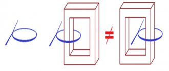
How does a transformer work? How to connect a transformer to the network?
How does a transformer work?
How to connect a transformer to the network? FAQ Part 2 The article discusses questions about the design, determination of overall power, connection and phasing of the windings of low-frequency power transformers.
Related topics.
Power supply for low frequency amplifier from available parts. ULF, part 3.
How to connect Notepad with the Windows Calculator to make calculations easier?
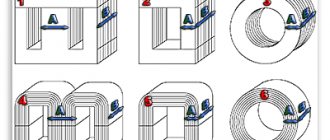
The magnetic core of the low-frequency transformer consists of steel plates. Using laminations instead of a solid core reduces eddy currents, which increases efficiency and reduces heat.
Magnetic cores of type 1, 2 or 3 are produced by stamping.
Magnetic cores of types 4, 5 or 6 are produced by winding a steel tape onto a template, and magnetic cores of types 4 and 5 are then cut in half.
Magnetic cores are:
1, 4 – armored,
2, 5 – rod,
3, 6 – ring.
True, I have never seen stamped ring magnetic cores.
To determine the cross-section of the magnetic circuit, you need to multiply the dimensions “A” and “B”. For calculations in this article, the section size in centimeters is used.
Transformers with twisted rod position 1 and armored magnetic cores position 2.
Transformers with stamped armored magnetic cores, position 1, and core magnetic cores, position 2.
Transformers with twisted ring magnetic cores.
More information about magnetic cores in the chapter - “Disassembly and assembly of transformers”.
Return to top menu
How to determine the overall power of a transformer
The overall power of a transformer can be approximately determined by the cross-section of the magnetic core. True, the error can be up to 50%, and this is due to a number of factors. The overall power directly depends on the design features of the magnetic core, the quality and thickness of the steel used, the size of the window, the amount of induction, the cross-section of the winding wire and even the quality of the insulation between the individual plates.
The cheaper the transformer, the lower its relative overall power.
Of course, it is possible through experiments and calculations to determine the maximum power of a transformer with high accuracy, but there is not much point in this, since during the manufacture of the transformer, all this is already taken into account and reflected in the number of turns of the primary winding.
So, when determining the power, you can be guided by the cross-sectional area of the set of plates passing through the frame or frames, if there are two of them.
To make calculations easier, take a look at this link: How to pair Notepad with the Windows Calculator to make calculations easier?
P = B * S² / 1.69
P – power in Watts,
B – induction in Tesla,
S – cross section in cm²,
1,69 – constant coefficient.
Example:
First, we determine the cross-section, for which we multiply the dimensions A and B.
S = 2.5 * 2.5 = 6.25 cm²
Then we substitute the cross-sectional size into the formula and get the power. I chose 1.5Tc induction, since I have an armored twisted magnetic circuit.
P = 1.5 * 6.25² / 1.69 = 35 Watt
If you need to determine the required cross-sectional area of the manipulator based on the known power, you can use the following formula:
S = ²√ (P * 1.69 / B)
Example:
It is necessary to calculate the cross-section of an armored stamped magnetic circuit for the manufacture of a 50-watt transformer.
S = ²√ (50 * 1.69 / 1.3) = 8cm²
The magnitude of induction can be found in the table. You should not use maximum induction values, as they can vary greatly for magnetic cores of different quality.
Maximum inductance guide values
| Type of magnetic circuit | Magnetic induction max (T) at transformer power (W) | ||||
| 5-10 | 10-50 | 50-150 | 150-300 | 300-1000 | |
| Armor stamped | 1,2 | 1,3 | 1,35 | 1,35 | 1,3 |
| Armor twisted | 1,55 | 1,65 | 1,65 | 1,65 | 1,6 |
| Ring twisted | 1,7 | 1,7 | 1,7 | 1,65 | 1,6 |
Return to top menu
Where can I get the original transformer?
The easiest way is to pick up a ready-made transformer on the radio market, if, of course, it is available in your city. There you can also agree on rewinding the transformer. But both transformers and services for rewinding them are quite expensive.
The picture shows part of a tray at a radio market where you can buy transformers in the city of Cishinau (Chisinau).
If you have some unnecessary equipment lying around in your barn or on your balcony, then there are probably transformers in it. Any dismountable network transformer is very easy to modify to suit your needs. The most important thing is that its overall power is enough.
If the power of the transformer is less than required, then under load the output voltage of the transformer may drop significantly. But this is also not a problem, since microcircuits such as TDA2030, TDA2040 and TDA2050 can operate with a significant reduction in supply voltage, namely: ±6, ±2.5 and ±4.5 Volts, respectively.
It is unlikely that the secondary windings of the found transformer will be suitable for current and voltage, but the primary winding is already designed for the voltage of the lighting network and this is the best help, since it is much easier to rewind the secondary winding than the primary.
Well, if this is a standard unified transformer, then by its name you can accurately determine the voltages and maximum permissible currents of the secondary windings. Such transformers cannot be disassembled, so before buying one, you need to check the name with the data in the directory.
At the end of the article there is a link to a reference book in which you can find detailed information about most unified transformers of Soviet and post-Soviet production.
If it is a transformer without identification marks, then the probability that it will have to be rewound will tend to 99%. It's not worth paying a lot for such a trans.
When purchasing a transformer with a ring magnetic core, you should keep in mind that not every transformer can be disassembled without damaging the primary winding.
- Suitable for replacing the secondary winding.
- It is necessary to wind the primary winding.
- It is necessary to wind the primary winding.
Return to top menu
How to connect an unknown transformer to the network?
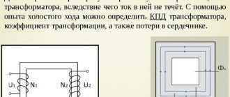
Before connecting the transformer to the network, you need to test its windings with an ohmmeter. In step-down transformers, the resistance of the mains winding is much greater than the resistance of the secondary windings and can differ by a hundred times.
There can be several primary (network) windings, or a single winding can have taps if the transformer is universal and designed for use at different mains voltages.
In two-frame transformers on core magnetic cores, the primary windings are distributed over both frames.
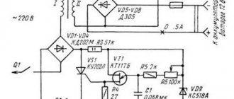
When testing transformers, you can use the diagram below. If switched on incorrectly, the FU fuse will protect the network from short circuit and the transformer from damage.
We calculate the fuse current in the usual way:
I=P/U
I – current for which the fuse is designed (Ampere),
P – overall power of the transformer (Watt),
U – mains voltage (~220 Volts).
Example:
35 / 220 = 0.16 Ampere
The closest value is 0.25 Ampere.
Circuit for measuring the no-load current (IO) of the transformer. The XX current of the transformer is usually measured to exclude the presence of short-circuited turns or to ensure that the primary winding is connected correctly.
When measuring the XX current, you need to gradually increase the supply voltage. In this case, the current should increase smoothly. When the voltage exceeds 230 volts, the current usually begins to increase more sharply. If the current begins to increase sharply at a voltage significantly less than 220 Volts, it means that either you have chosen the primary winding incorrectly, or it is faulty.
Low power factor: causes and consequences
A low indicator leads to a maximum elimination of the energy component. Special devices are used for compensation, which reduce electricity consumption and increase the efficiency of the device.
Load losses in network elements
Loading leads to redistribution and reduction of the energy component. The voltage level drops, which causes significant overheating of the device. The consequence is loss of efficiency and performance, rapid failure of equipment.
The specialist minimizes load-type forces. This allows you to increase the starting torque of the device.