What is a transformer
A transformer is an electromagnetic device designed to convert alternating current of one voltage into alternating current of another voltage at the same frequency. The operation of the transformer is based on the use of the phenomenon of electromagnetic induction.
An alternating electric current (a current that varies in magnitude and direction) induces an alternating magnetic field in the primary coil. This alternating magnetic field induces an alternating voltage in the secondary winding. The magnitude of the EMF voltage depends on the number of turns in the coil and on the rate of change of the magnetic field.
The ratio of the number of turns of the primary and secondary windings determines the transformation ratio: k = w1 / w2; Where:
- w1 - number of turns in the primary winding;
- w2 is the number of turns in the secondary winding.
If the number of turns in the primary winding is greater than in the secondary, it is a step-down transformer.
If the number of turns in the primary winding is less than in the secondary, it is a step-up transformer.
The same transformer can be both step-down and step-up, depending on which winding is supplied with alternating voltage.
Transformers without a core or with a core of high-frequency ferrite or alsifer are high-frequency transformers (frequency above 100 kilohertz). Transformers with a ferromagnetic core (steel, permalloy, ferrite) are low-frequency transformers (frequency below 100 kilohertz)
Interesting material to familiarize yourself with: what you need to know about the design of a power transformer.
High-frequency transformers are used in telecommunications equipment, radio communications, etc. Low-frequency transformers are used in audio frequency amplification technology and in telephone communications. Transformers with a steel core (a set of steel sheets) occupy a special place in electrical engineering. The development of the electric power industry directly depends on powerful power transformers. The power of power transformers ranges from several watts to hundreds of thousands of kilowatts and above. The classification of transformer types is presented in the table below.
Table of characteristics of transformers by their main types.
A little history
Thanks to the English physicist Michael Faraday, in 1831, humanity became acquainted with electromagnetic induction. The great scientist was not destined to become the inventor of the transformer, since his experiments involved direct current. The prototype of the device can be considered the unusual induction coil of the Frenchman G. Ruhmkorff, which was presented to the scientific world in 1848.
In 1876, Russian electrical engineer P. N. Yablochkov patented an alternating current transformer with an open core. The device owes its modern appearance to the English brothers Hopkinson, as well as the Romanians K. Tsiperanovsky and O. Blati. With their help, the design acquired a closed magnetic circuit and has preserved the circuit to this day.
Types of magnetic cores
What is a power transformer
Two or more windings are put on a closed core (magnetic core), made of steel sheets, one of which is connected to an alternating current source. The other (or other) winding is connected to the consumer of electric current - the load. The alternating current passing through the primary winding creates a magnetic flux in the steel core, which induces an alternating voltage in each turn of the winding - coil. The voltages of all turns add up to the output voltage of the transformer. The shape of the core - magnetic circuit, can be W-shaped, O-shaped and toroidal, in the form of a torus. Thus, in a power transformer, electrical power from the primary winding is transferred to the secondary winding through the magnetic flux in the magnetic core.
It will be interesting➡ The design of a toroidal transformer and its advantages
There are a lot of consumers of electrical energy: electric lighting, electric heaters, radio and television equipment, electric motors and much more. And all these devices require different voltages (AC and DC) and different powers. This problem is easily solved using a transformer. From a household network with an alternating voltage of 220 volts, you can obtain an alternating voltage of any value and, if necessary, convert it into direct voltage.
The efficiency of the transformer is quite high, from 0.9 to 0.98 and depends on losses in the magnetic circuit and on magnetic stray fields. The cross-sectional area of the magnetic circuit S depends on the magnitude of the electrical power P. Based on the value of the area S, the number of turns w per 1 volt is determined when calculating the transformer:
w = 50/S.
The power of the transformer Рс is selected from the required load value Рн plus the value of losses in the core.
When calculating a transformer, with a certain degree of accuracy, we can assume that the load power in the secondary winding Pн = Un * Iн and the power consumed from the network in the primary winding Pc = Uc * Ic are approximately equal. If losses in the core are neglected, then the equality is obtained: k = Uс / Un = Iн / Iс.
Transformers and their application/
Design
The transformer design assumes the presence of one or more individual coils (tape or wire), located under a single magnetic flux, wound on a core made of a ferromagnet.
The most important structural parts are as follows:
- winding;
- frame;
- magnetic circuit (core);
- cooling system;
- insulation system;
- additional parts necessary for protective purposes, for installation, to provide access to the output parts.
In devices you can most often see two types of winding: the primary, which receives electric current from an external power source, and the secondary, from which the voltage is removed.
The core provides improved return contact of the windings and has reduced magnetic flux resistance.
Some types of devices operating at ultrahigh and high frequencies are produced without a core.
The production of devices is established in three basic winding concepts:
- armored;
- toroidal;
- core.
The design of core transformers involves winding the winding onto the core strictly horizontally. In armor-type devices it is enclosed in a magnetic circuit and placed horizontally or vertically.
Reliability, operational features, design and principle of operation of the transformer are taken without any influence from the principle of its manufacture.
Transformers and their applications
A transformer is a device used to increase or decrease alternating voltage without changing its frequency and with virtually no power loss. A transformer consists of two or more coils mounted on a common core. The coil that is connected to the AC voltage source is called primary, and the coil to which the load (consumers of electrical energy) is connected is called secondary. Transformer cores are made of electrical steel and assembled from separate plates insulated from each other (to reduce energy losses due to the occurrence of eddy currents in the core).
Transformer coils typically contain different numbers of turns, with more voltage being applied to the coil with more turns. If a transformer is used to increase voltage, the winding with fewer turns is connected to the voltage source, and the winding with more turns is connected to the load. To lower the voltage, everything is done the other way around. At the same time, we should not forget that no more than the rated voltage (the one for which it is designed) can be applied to the primary winding.
The transformation ratio is the ratio of the number of turns in the primary winding to the number of turns in the secondary winding. It is also equal to the ratio of the EMF in the windings. In the absence of losses in the windings, the transformation coefficient is equal to the ratio of the voltages at the winding terminals: k=U1/U2. For a step-down transformer, the transformation ratio is greater than 1, and for a step-up transformer, it is less than 1. The operating principle of the transformer is based on the phenomenon of electromagnetic induction. When alternating current flows through the primary coil, an alternating magnetic field and magnetic flux arise around it, which also penetrates the second coil. As a result, a vortex electric field appears in the secondary coil and an induced emf appears at its terminals.
The transformer is characterized by an efficiency equal to the ratio of the power released in the secondary coil to the power consumed by the primary coil from the network. Good transformers have an efficiency of 99 - 99.5%. An important property of a transformer is its ability to transform load resistance. Consider a transformer with an efficiency of approximately 100%. In this case, the power released in the secondary circuit of the transformer will be equal to the power consumed by the primary winding from the voltage source. For such a transformer, the power consumed from the voltage source will be purely active. Power in the primary circuit of the transformer P1=(U12)/R1, and in the secondary circuit P2=(U22)/R2.
It will be interesting➡ How does a power transformer work and where is it used?
Since P1=P2 and U1=kU2, then R1=k2R2.
Thus, a load with resistance R2 connected to an alternating voltage source through a transformer will be equivalent in power to a load with resistance R1 connected without a transformer. Laboratory autotransformers are widely used to regulate alternating voltage. Autotransformers are designed for connection to an alternating voltage network of 220 V or 127 V. As a rule, the output voltage of the autotransformer is smoothly regulated up to 250 V.
The transformer winding is made of insulated wire in one layer. In areas of the winding that are touched by the moving contact with the carbon insert, the insulation is cleaned. When the contact moves, the carbon insert short-circuits a turn of wire. However, due to the small voltage on one turn and the noticeable resistance of the carbon insert, an allowable current flows through the closed turn.
The primary winding of an autotransformer is part of its secondary winding and therefore there is a galvanic connection between the primary and secondary windings of the transformer. Consumers cannot be directly connected to the secondary winding of the autotransformer, one of the wires of which may be connected to ground. This connection will lead to an accident or mishap. When working with an autotransformer, it is prohibited to ground the secondary circuit. Let us briefly consider the simplest calculation of low-power transformers for household radio equipment.
The power of the transformer (in W) is numerically equal to the square of the area (in cm2) of the cross section of the middle core of the magnetic core. Knowing the rated power of the transformer, you can find the current in the primary winding at the rated load in the secondary windings. The diameter of the winding wire is selected based on (2.5-3) A/mm2 of the wire cross-section. For standard magnetic cores used for the manufacture of transformers, the number of turns per 1 volt is approximately equal to the quotient of 50 divided by the cross-sectional area of the central core of the magnetic core, expressed in cm2. However, depending on the quality of the magnetic core, the coefficient can vary from 35 to 65.
Transformer.
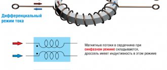
The total resistance of an inductor with a ferromagnetic core depends on the strength of the current flowing through it. The resistance of the coil, depending on the strength of the flowing current, first increases, reaches a maximum value, and then decreases. The nonlinear increase in no-load current depending on the voltage applied to the primary winding begins at approximately 0.8 Un. The rated voltage of the primary winding of the transformer is selected so that the no-load current is 5-10% of the rated current. At a voltage of 1.1 Un, the no-load current should not exceed 20-25% of the rated current of the loaded transformer.
Material on the topic: how a toroidal transformer works and what are its advantages.
Parallel connection
Connecting secondary windings
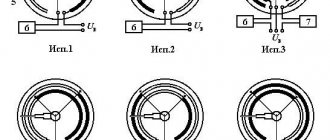
Parallel connection of identical secondary windings allows you to increase the power (current) at the output of the device. This way it is possible to increase the efficiency and load capacity of the serviced line.
When using this approach, you will need to take into account one important detail related to the order of connection of the secondary windings. To obtain the expected results, the windings must be turned on in phase, which means connecting the same type of ends of all three coils at one point. If this rule is violated, the voltage at the output of two windings connected out of phase will be close to zero (the substitution principle applies). When this error is made when turning on a transformer, its power and efficiency are significantly reduced. If, during a secondary check, it is discovered that the voltage has not changed compared to a single connection, then the coils are connected in phase.
A converter device, defined as a 220 to 380 Volt 3 phase transformer, can be obtained if a special circuit is used to increase the output voltage. Its peculiarity is the presence of one primary and three secondary windings connected in a star or delta circuit.
Transformer operating modes
There are three operating modes of the transformer: idle mode, short circuit mode, operating mode. The transformer is “idling” when the leads from the secondary windings are not connected anywhere. If the transformer core is made of a soft magnetic material, then the no-load current shows what losses occur in the transformer due to magnetization reversal of the core and eddy currents.
In short circuit mode, the terminals of the secondary winding are short-circuited together, and a small voltage is applied to the primary winding, so that the short circuit current is equal to the rated current of the transformer. The amount of loss (power) can be calculated if the voltage in the secondary winding is multiplied by the short circuit current. This transformer mode finds its technical application in instrument transformers.
If you connect a load to the secondary winding, a current appears in it, inducing a magnetic flux directed opposite to the magnetic flux in the primary winding. Now, in the primary winding, the EMF of the power source and the induced emf of the supply are not equal, so the current in the primary winding increases until the magnetic flux reaches its previous value.
Transformer operating modes.
For a transformer in active load mode, the following equality is true: U_2/U_1 =N_2/N_1, where U2, U1 are the instantaneous voltages at the ends of the secondary and primary windings, and N1, N2 are the number of turns in the primary and secondary windings. If U2 > U1, the transformer is called a step-up transformer, otherwise we have a step-down transformer. Any transformer is usually characterized by the number k, where k is the transformation ratio.
It will be interesting➡ What are isolation transformers
Special
In their fundamental design they are no different from power ones; moreover, in their purpose too, they are needed to provide power supply. Another thing is that the nature of their load is specific. Usually the required power is very large and also unevenly distributed over time. For example, a three-phase welding transformer is designed for long-term operation in almost short circuit mode, with a very low resistance, connected to the output windings. In this case, the load is pulsed and asymmetrical in nature. In approximately the same mode, which is hardly acceptable for a conventional transformer, a device made to power low-resistance and very powerful electric furnaces or hardening inductors with high-frequency currents operates.
Types of transformers
Depending on their application and characteristics, transformers come in several types. For example, in electrical networks of populated areas and industrial enterprises, power transformers are used, the main task of which is to reduce the voltage in the network to the generally accepted 220 V. If a transformer is designed to regulate current, it is called a current transformer, and if the device regulates voltage, then it is a transformer voltage. In ordinary networks, single-phase transformers are used; in networks with three wires (phase, neutral, ground), a three-phase transformer is needed. Household transformer, 220V, is designed to protect household appliances from voltage surges.
Types of transformers
The welding transformer is designed to separate the welding and power networks, to reduce the voltage in the network to the value required for welding. The oil transformer is intended for use in networks with voltages above 6,000 Volts. The design of the transformer includes: a magnetic core, windings, a tank, as well as covers with inputs. The magnetic core consists of 2 sheets of electrical steel, which are insulated from each other; the windings are usually made of aluminum or copper wire. Voltage regulation is done using a tap that connects to the switch. There are two types of tap switching: switching under load - on-load tap-changer (regulation under load), and also without load, after the transformer is disconnected from the external network (PBV, or switching without excitation). The second method of voltage regulation has become more widespread.
Speaking about the types of transformers, it is impossible not to talk about the electronic transformer. An electronic transformer is a specialized power source that is used to convert 220V voltage to 12 (24)V at high power. The electronic transformer is much smaller than a conventional one, with the same load parameters.
Measuring
Measuring the parameters of an electrical circuit is the most important task in the energy sector. If it is necessary to determine currents of relatively small magnitudes, then there are no particular difficulties; many simple and reliable devices have been invented - both magnetoelectric and digital. It’s another matter if the current reaches tens of amperes, or even hundreds. Here you already need a three-phase current transformer, on the secondary windings of which you can obtain multiple-reduced values measured by conventional standard ammeters. Theoretically, of course, it is possible to make a device that can withstand enormous current and have ultra-low resistance, but in this case the frame and the entire mechanism will be of cyclopean dimensions. And the cost of such an ammeter will be comparable to the price of all other substation equipment taken together.
Safety precautions
During operation, certain rules must be observed:
- if cracks appear on the case, noise or vibration, the autotransformer is immediately turned off;
- It is prohibited to leave equipment for which continuous monitoring is provided unattended;
- you cannot connect a motor whose power is more than 70% greater than the power of the autotransformer;
- These devices must not be used openly, covered, covered with ventilation openings, or placed on them with other equipment or objects.
When carrying out repairs on an autotransformer or the device it is part of, it is necessary to disconnect it from the power supply.
Decoding the main parameters
The diversity in design and wide range of parameters of transformers have led to the need for their marking according to a special standard. Without having a technical description at hand, the characteristics of the device can be determined by the information printed on its surface, expressed in an alphanumeric code.
The marking of power transformers contains 4 blocks.
Let's decipher the first three blocks:
Decoding of markings: 1,2,3 blocks
- The first letter "A" is attached behind the autotransformers. In its absence, the letters “T” and “O” correspond to three-phase and single-phase transformers.
- The further presence of the letter “P” informs about devices with split winding.
- The third letter means cooling; the oil natural cooling system is assigned the letter “M”. Natural air cooling is marked with the letter “C”, oil cooling with forced airflow is designated “D”, with forced oil circulation – “C”. The combination “DC” indicates the presence of forced oil circulation with simultaneous air blowing.
- The letter “T” marks three-winding converters.
- The last sign characterizes the features of the transformer:
- “N” – on-load tap-changer (voltage regulation under load);
- space – switching without excitation;
- “G” – lightning protected.