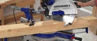
DIY worm gear
The pride of many summer residents is a homemade walk-behind tractor, assembled with their own hands from parts that have served their age. Installing an electric motor or a small gasoline motor from an old scooter or motorcycle onto a frame with wheels is not difficult even for a novice amateur mechanic. But what you have to think about is the gearbox for the walk-behind tractor.
Walk-behind tractor design
Schemes for assembling homemade walk-behind tractors are as varied as the spare parts in each owner’s garage. Dimensions are also chosen for practical reasons.
With different compositions and dimensions, there are required elements:
- The frame is a durable structure for attaching other parts.
- Wheels - from homemade metal to factory-made rubber. The position of the wheel or wheelset axle is fixed relative to the frame by iron struts with pressed-in bearings.
- Engine - power from 5 to 10 horsepower. You can even use an electric motor with a battery, but the most popular are engines from a scooter or motorcycle. This choice is good because it has a ready-made speed control and even a transmission device.
- Gearbox is a unit for transmitting rotation from the engine to the actuator, converting speed and direction.
But the first gearbox you come across may not be suitable. You need to choose the type of structure, calculate the size of each part, so that the speed and power of movement of the mounted cultivator allows you to cultivate the land in a convenient mode - neither quickly nor slowly.
Types of gear units
The transmission of rotational motion from the motor shaft to the actuator shaft can be carried out by direct connection of the axes, if the speed and power of rotation of the engine are acceptable for operation, and the axes of the drive and driven shafts coincide.
Such cases are extremely rare, and with several attachments for different purposes, direct transmission absolutely cannot be used. To match the speed and power of the drive and driven shafts, 4 types of mechanisms and their combinations are used.
Main types of gears:
- belt;
- chain;
- gear;
- worm
The worm gear is structurally limited by the speed-reducing function; the rest can be used in both downshifts and overdrives. In addition, such a gearbox always has a driven axis perpendicular to the drive shaft.
This scheme is called an angular gearbox. In addition to the worm gear, you can change the direction of the axis using a spatial planetary mechanism. Belt and chain drives keep the driven axis parallel to the engine axis.
In simple devices, reverse is possible only when the rotation of the engine changes.
Motoblocks use engines with a high number of revolutions per minute, which can be verified in the product data sheet. This means that you need to make a gearbox with your own hands to reduce the speed, and it is better to choose what type of homemade gearbox for a walk-behind tractor, knowing the characteristics of each type.
Belting
The pulley or belt that transmits rotation from shaft to shaft is familiar to every motorist who has looked under the hood of the engine compartment. The rotation speed reduction coefficient is determined by dividing the radius of the small driven wheel by the radius of the large driving wheel.
The advantages of belt gearboxes are their ease of manufacture and repair, and a wide variety of parts. And the disadvantages of the belt:
- belt stretching, decreased adhesion to the pulley due to temperature and wear;
- slippage during sudden increases in torque;
- short service life.
The shortcomings are compensated by using a spring-loaded roller that presses on the surface of the belt between the wheels, and by using a toothed belt on pulleys with transverse chamfers. Belt gearboxes require the drive and driven pulleys to be in the same plane; bending or twisting the belt will quickly lead to it breaking.
Chain type
The operating principle of a chain drive is similar to a belt drive, but sprockets are installed instead of pulleys, and the belt is replaced by a chain. Such a homemade gearbox will not allow slipping, and under similar conditions it will work much longer.
Just like a belt gearbox, a chain gearbox must have drive and driven sprockets in the same plane, and its gear ratio is calculated by the ratio of their teeth. The weight of this design is greater than that of a belt design, but it is safer to install it on powerful walk-behind tractors.
Unlike a belt drive, a chain drive requires caution or additional protective measures.
If a rotating implement collides with a thick root in the soil, its drag force will be transferred to the motor, possibly damaging it.
Until the engine fails or switches off, it will try to rotate with maximum power along with the frame around the driven axis of the gearbox. The greater the engine power, the stronger the tipping torque will be.
Application
If we talk about the automotive industry, this transmission is most often installed on trolleybuses. In addition, it is widely in demand in the industrial sector. Worm gears are used in many machine tools and material handling machines. Typically, the scope of application of this device is limited to devices with a rated power of less than 100 kW. It is not used on more powerful tools due to low efficiency and frequent heating during operation, which would require the use of additional cooling systems.
Worm gear
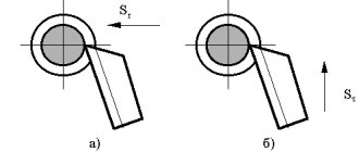
Gears can have shaft axes in different planes. The leading part, a worm, has no teeth. Instead, a thread is cut with a module similar to a gear.
The worm transmits rotation to the worm wheel through the pressure of the surface of the threaded thread on the involute of the tooth as the planes slide relative to each other. The worm unit has low efficiency and reduction gear is impossible.
Large resistance does not allow the wheel to move the worm. It is used in lifting mechanisms and precision moving devices.
Design
The worm gear gets its name from the driving part that transmits torque. The driven part has a tooth with an oblique cut. Along the rim there is a radial understatement of the surface. This increases the line of contact between the thread and the tooth.
The rotation axes of the parts are located at an angle. Usually it is 90°, but can be 45°. This arrangement of parts is used in heavily loaded low-speed gears, with a point speed on the outer surface of less than 5 m/sec.
When the gear interacts, the thread surface does not push the teeth in the direction of rotation, but slides along the involute, as if pushing it aside. As a result, strong friction and heating of parts at the point of contact occurs.
The worm pair must be well lubricated, cooled and have anti-friction properties.
The material of the worm cannot be changed; it is cut from chromium steel and undergoes hardening, grinding of the thread surface or sugaring - processing with a plate with a shallow depth of cut.
The tool pushes the surface of the thread rather than cutting it. A hardening is created on the top layer, strengthening the working surface and making it smooth.
Material for the crown
The gear ring is made of a relatively soft material with high abrasion resistance. Tin bronze and brass are mainly used. For low-speed manual transmissions, the crown can be made of gray cast iron. Depending on the rotation speed, the ring gear is made of the following material:
- 5 – 25 m/sec – tin bronzes OF10-1, ONF;
- ≤ 5 m/sec – Br.AZh9-4, aluminum-iron bronze;
- ≤ 2 m/sec – the crown can be made of cast iron.
Bronze is much more expensive than steel and is softer. Parts are made entirely from it, the dimensions of which are within 160 mm. Large parts are machined from steel and only the crown is bronze. It is hot seated on the shaft and secured with pins along the connection line so that the crown does not rotate. After cooling, the wheel is finished and the tooth is cut.
The diameter of the wheel is calculated along the centerline of the tooth - the width of the tooth and the cavity are equal. The outer radius used for manufacturing and calculations is determined theoretically. Once the processing is completed, it is located outside the actual wheel rim.
Sliding occurs along the line of the pitch diameter - the middle of the tooth in height. It is calculated by the formula:
d2 = m z2,
where d2 is the pitch diameter of the gear; m – module; z2 – number of wheel teeth.
The outer radius of the tooth has one center with the axis of the worm.
Ring gear width
The width of the worm wheel crown is determined by the number of turns of the screw using the formula:
with Z1 = 1 or 2, b2 = 0.355aw;
if Z1 = 4, then b2 = 0.315ac,
where b2 is the width of the crown; 0.315 and 0.355 – calculated coefficient; Z1 – number of screw thread starts; a – center-to-center distance; aw is the distance taking into account the displacement of the worm relative to the gear.
The offset distance determines the size of the gap between the working elements of the parts.
Calculation of worm gear ratio
The driving part that transmits rotation, the worm, has no teeth. Threads are cut on it with the number of starts: 1, 2, 4. Worms with 3 turns are not provided for by GOST. They can be considered and calculated only theoretically. When calculating the gear ratio, instead of the number of gear teeth, the number of thread starts is taken.
Calculate the gear ratio of the worm gear, the formula is similar to other gears:
U = Z2 ÷ Z1,
where U is the gear ratio; Z1 – number of passes on the worm; Z2 – number of teeth on the wheel.
Reverse transmission of torque from the wheel to the worm shaft is impossible. Due to strong tooth friction and low transmission efficiency, the wheel cannot be a drive wheel. This allows you to avoid using brakes in lifting mechanisms. It is enough to regulate the rotation of the worm shaft.
Gear ratio calculation
The gear ratio of a worm gear is calculated by the ratio of the sliding speed of the worm and the shaft.
Where V1 is the sliding speed of the worm; V2 is the sliding speed of the worm wheel. Similar to w1 and w2 angular velocities; dδ1, dδ2 – diameters.
By substituting the formulas for the values of sliding speeds and mathematical abbreviations, the formula for the gear ratio of the worm gear is obtained:
Where i is the gear ratio. In a worm gear it is equal to the gear ratio.
The characteristics of worm gears are standardized according to GOST 2144-76. For a worm with 1 and 2 starts, the gear ratio can be 8-80. For 4-way worms the range of values is smaller, in the range of 30-80.
Download GOST 2144-76
Classification
In the direction of the turn, transmissions are mostly right-handed. Sometimes the left direction of the thread is found.
Worm gears are classified according to the shape of the outer surface of the worm:
- cylindrical;
- Globoid.
The concave surface of the drive part increases the number of teeth that are in mesh at the same time. As a result, efficiency and transmission power increase. The disadvantage of globoid worms is that they are difficult to manufacture. The coils must be of the same height with a concave outer surface.
Worms are distinguished by the shape of the thread:
- Archimedean;
- convolute;
- nonlinear.
The Archimedes worm is distinguished by a straight involute in cross-section. The convolute has a convex configuration, close to the shape of a regular gear. Nonlinear profiles have a convex and concave surface.
The gear wheel has an inclined tooth of a reverse configuration, the shape of which coincides with the cavity between the threads.
The location of the worm relative to the wheel can be:
The upper one is optimal for high-speed gears. The side one is the most compact. With the crankcase lubrication method, the oil is in the sump and the lower part, rotating, lubricates the rest; the lower location of the worm is more convenient.
Worm wheels are helical gears. The axes of the parts are usually located at an angle of 90°. In heavily loaded mechanisms, the angle can be 45°.
Gear wheels are divided according to the tooth profile:
- roller;
- concave;
- straight.
By type they can be:
- with continuous rotation – full;
- gear sector.
The sector can be of different sizes, from half a circle to a working length shorter than a worm.
Advantages and disadvantages
A feature of the worm gear is the presence of braking torque and a large range of gear ratios and torque. Positive characteristics include:
- gear ratio within 8–100;
- works quietly;
- rotation starts and stops smoothly;
- high precision of movements;
- possibility of displacement by a small amount;
- compactness of the unit;
- self-braking transmission.
Transmission of motion in a pair of worm and worm wheel is possible only in one direction. When the driven part tries to rotate, a braking torque occurs. This is used in swing drives and lifting mechanisms.
The main disadvantage is the power loss associated with high friction. This leads to rapid wear of parts, especially the wheels. Disadvantages include:
- low efficiency;
- friction;
- high heat;
- making a crown from expensive materials;
- frequent eating;
- rapid wear;
- constant adjustment of engagement by tightening the worm;
- complex manufacturing.
Worm gearing requires high precision in the manufacture of screw gearing and cleanliness of processing. The transmission does not tolerate dust and other debris entering the work area. Requires intensive lubrication and cooling.
Application of the mechanism
The worm gear is capable of replacing a multi-stage gearbox with small dimensions. Its gear ratio is determined by the value 100; in individual nodes it can be significantly higher.
The use of a worm gear is advisable in mechanisms that require high precision at low speed:
- worm gearboxes;
- in lifts;
- elevators;
- winches;
- steering mechanisms;
- precise adjustment of the position of the tool in the machines;
- adjustment in CNC;
- devices
Self-braking and precision movement are mainly used.
Worm wheel cutting
During design, a model of a worm wheel is created. Using it you can easily determine the cutting method:
- cutter approach from below;
- end
The end one requires a tool that exactly replicates the worm. Gives good accuracy and cleanliness of processing. It is difficult to align the cutter, it is necessary that at the end of processing it has a position relative to the wheel that exactly corresponds to the worm.
Cutting teeth on the crown
The worm wheel has a semicircular recess along its outer diameter. This allows the parts to fit better along the involute and shift the axis, increasing the contact area. The center of the recess radius must coincide with the axis of the worm.
Worm wheel cutters must have the same outside diameter as the worm. Externally, it repeats the shape of the leading part, only instead of a continuous thread line there are rows of cutters.
The cutting plate exactly matches the thread in shape, but is wider by the size of the gap.
As a result, the configuration of the counter part - the worm wheel - exactly repeats the shape of the thread, the depressions coincide with the protrusions of the threads.
The cutter is aligned in the plane of the worm axis, touching its surface. The ring gear rotates around a vertical mandrel or its own shaft, providing tangential feed of the outer surface relative to the axis of the cutting tool.
Worm wheel cutting occurs with the synchronous movement of the tool and the part rotating around their axes. The rotation speed ratio is determined by the gear ratio. With each revolution, the crown moves closer to the rotating cutter.
The cutting tool can be fed from below and from above. But in most cases, radial cutting is used as the most convenient and accurate.
Repair thread
Sometimes you need to make one part to replace it in the gearbox. The workshop does not always have a complete set of cutters with all normalized diameters.
If a worm wheel is cut with a cutter with a larger diameter than the radius of the worm, the fit will be worse and the contact patch will be smaller. The sliding line will move towards the top of the tooth.
When cutting with a smaller diameter with the same module, the load will be on the top of the thread. The error can be compensated by shifting the tool and adjusting the distance between the axes.
But friction and wear will still be greater, and efficiency will drop.
You can cut the worm wheel with a cutter with a diameter larger than the worm for backlash-free clutch. In this case, a special cutter is used with different profile angles for the right and left sides. The axis of the cutter is turned in the direction of increasing the inclination of the tooth. Conventional gear hobbing machines must be modified to machine backlash-free clutches.
Due to the lack of clearance between the working elements, the surface quickly wears out and you have to constantly make adjustments. Backlash-free clutches are used for high precision and high loads with low activity of the pair, for example, in rolling mills to adjust the roll pressure - the thickness of the rolled metal.
To manufacture one or several wheels with non-standard dimensions, a mandrel with one cutter in the shape of the cavity between the teeth can be used. The tool rotates constantly. The wheel rotates synchronously with the tool. After each revolution of the cut, it is rotated to the size of the tooth module and for a full revolution, it moves towards the mandrel with the cutter to the depth of the cut.
The disadvantage of the method of making a crown is the length of the process. One cutter processes a part several times longer than a milling cutter. Taking into account the abrasion of the cutter, it is necessary to do roughing and finishing.
The worm wheel differs from others in its appearance and processing method. It is done exactly for a specific worm.
Worm gearbox: description.types.principle of operation,repair,photo,video
The worm gearbox is often considered an important part not only in the automotive industry.
The worm gear is considered an important part wherever it is necessary to increase torque and reduce the number of rotations of the drive.
Such a mechanism is used to drive gates, lifts, machines for processing metals, wood and other similar devices. Almost every person has seen a worm gearbox, sometimes without even knowing it.
The fact is that such a drive mechanism is often hidden in a housing so that the mechanism does not become clogged with dust and other debris, and this significantly extends the service life of the mechanism.
The worm gearbox is so often used because the efficiency of this mechanism is very high.
Such a mechanism can be either small or large.
Due to its small size, worm gears are most often used in automobile production. Each converter has its own gear ratio. This number is often indicated on the packaging of the device, or on the body itself.
Advantages and disadvantages
Worm gears, due to their design features, have both advantages and disadvantages.
Among the advantages, it is worth noting the smooth running, self-braking effect, low noise level, large gear ratio using only two parts.
Among the disadvantages, attention should be paid to the relatively low efficiency, increased wear, jamming, and high heat generation due to friction forces.
Low efficiency determines the use of such mechanisms when transmitting relatively small powers up to 100 kW.
To prevent rapid wear and jamming, it is necessary to comply with the requirements for assembly accuracy and adjust the mechanisms. High heat generation requires special installations to remove excess heat.
The difference between gearboxes mainly comes down to the differences in the worms and gears from which a given worm gearbox is assembled.
Worms are divided into types according to the following characteristics:
- by number of thread starts: single-start, multi-start
- in the direction of thread cutting: right, left
- according to the shape of the screw on which the thread is cut: cylindrical, globoid
- according to the shape of the thread profile: with a convolute profile, with an Archimedean profile, with an involute profile
- Gears are divided into types according to the following characteristics:
- by wheel type: wheel itself, gear sector, degenerate sector
- according to the profile of the teeth: straight, concave, roller (a rotating roller is used instead of teeth)
Worm gearboxes with a built-in motor are called worm gearmotors. In gearboxes, the motor shaft is most often located at right angles to the movable one. The layout of the worm gearbox is selected based on the specific requirements for the devices.
The engine can be located either on top of the driven wheel, or below and on the side. When positioned sideways, the engine is installed vertically.
Due to the vertical location, the process of lubrication of the shaft bearings, as well as cleaning of external elements, is complicated.
Various technologies are used to increase the gear ratio, but the most effective is the use of a larger number of stages.
To soften friction forces and increase resistance to seizing, special viscous lubricants or oils are used.
At low rotation speeds, lubrication is carried out using special oil baths or using special devices that spray lubricant into areas of high friction.
For worm gearboxes, the rotation speed of which is high, the use of baths is impractical, and forced lubrication with cooled lubricants is used.
The main advantages of a worm gearbox over gears are that the initial contact of the links occurs not at a point, but along a line.
Also, the input and output shafts can cross at different angles, but most often this angle is 90 degrees.
Also, a worm gear takes up much less space than a toothed gear with the same large gear ratio.
In addition to the worm gearbox, the worm gear is also used in regulation and control systems for various devices.
Thanks to self-braking, precise position fixation is ensured, and a large gear ratio (up to 1000) allows you to most accurately adjust the position, or use low-power motors.
Also, worm gears and worm gearboxes are excellent for installation as a transmission mechanism in lifting and winching mechanisms due to their design features.
Do-it-yourself winch: necessary material, step-by-step assembly
A hoist is a very necessary thing when there is a need to lift and fix a heavy thing at a height. Unlike gear hoists. The lever mechanism can lift a load of no more than 5 tons and only to the height of a person.
The hoist is controlled using a special handle, which is part of the structure.
Lever hoists are not suitable for handling heavy loads, so they are rarely used in large production. They found their application in the household and as an assistant for motorists.
Scope of application of lever manual hoist:
- Housing and communal services use this design for laying water supply pipes in dug trenches or installing hatches in sewer pits;
- Farmers and foresters pull out tree stumps or carry heavy logs;
- Car owners use the hoist as a jack - to lift the car, remove a wheel or pull the engine out from under the hood.
The main advantage of a lever hoist is that it can be used in small spaces, such as a barn or garage, or outdoors.
Disassembling the Chinese ratchet
To begin with, the cheapest ratchet for a Chinese truck was ordered. After receiving and inspecting this spare part, I began to think about further actions.
First, I cut off the rivets and removed the covers. I also unscrewed the plug and pulled out a spring and a ball - this was a worm stopper, it will no longer be needed.
Do-it-yourself worm pair - Metalworker's Guide
Various mechanical assistants are designed to reduce the expenditure of human physical strength when performing a number of jobs. One of the ancient types of draft devices that transforms and increases the applied force is the winch.
A wide range of types, low cost and relative ease of production made it quite accessible for self-production. Today we will tell you about winch options and do-it-yourself assembly technology.
Types of winches according to the method of converting forces
Depending on the mechanical transmission used, there are several main types of devices such as winches:
- Gear;
- Worm;
- Chain.
It should be noted that in the production of devices that convert mechanical energy, belt drives are practically not used, since the possible slipping of the belt along the pulley, which is beneficial in a number of wood- and metalworking machines in such devices, will interfere with their operation.
A winch using toothed wheels (gears) is used quite widely.
Its advantages include the following:
- a wide range of multiplicity of changes in the applied force, depending on the difference in the diameter of the gear parts and the number of shafts;
- the ability to install working shafts at various angles, up to 90 degrees in the case of using bevel gears;
- high mechanical strength of the entire device as a whole and its individual parts;
- maintainability, which consists in the interchangeability of individual parts.
The disadvantages of winches of this design include certain difficulties that arise when making them yourself.
It is sometimes quite difficult for a home craftsman to select a pair of gears with the given parameters due to the lack of a large number of available mechanisms.
In addition, not everyone is able to carry out transmission calculations and determine the required number of gear teeth. All of the above leads to the limited use of gear winches when making them yourself.
The second type of mechanical transmission is a worm gear, which involves the use of not only gears, but also a special screw with a large screw thread - a worm. Among factory options, worm winches are quite common.
Their features include the perpendicular arrangement of the working shafts, the need to use special parts - a worm and a worm wheel.
As the latter, in some cases ordinary gears can be used, but the manufacture of a suitable worm in the absence of specialized equipment and tools is not possible.
The latter circumstance also significantly limits the use of worm-wheel winches for their independent manufacture.
Perhaps the most suitable option for home craftsmen is a chain winch.
It is based on the use of a chain transmission, familiar to everyone from childhood, used in the favorite form of transport by many - a bicycle.
To obtain the required rotation transformation, it is only necessary to swap the driving (small sprocket) and driven (large sprocket) shafts.
The simplicity of the design and the availability of the main parts make this type of winch the most used for self-production.
DIY chain winch
We recommend starting work on making your own chain winch by selecting the main parts of the mechanism and making a base for the device. For it, it is better to use rectangular steel pipes with a cross section of 40x40 or 30x50 mm.
Cut the workpiece into individual parts using a hacksaw or grinder. Before joining the edges of the sawn pieces, carefully sand and remove any burrs that could cause injury.
It is convenient to perform assembly using a weld seam using a household welding machine with an operating voltage of 220 V. The parts can be assembled end-to-end to the sides or by filing the edges at an angle of 45°.
Having connected the parts of the base, we proceed to install the winch mechanism. To do this, you will need a pair of axles made from scraps of steel rods or pipes, and bearings for their ends. Attach the small sprocket of the chain drive to the drive shaft, and the large sprocket and drum for winding the steel cable to the driven shaft.
It is also easy to weld a cable spool yourself from several scraps of rods or tubes with a diameter of 8-10 mm, and two disks of sufficient diameter, cut from steel sheets.
The bearings can be secured either by welding or by bolt-nut pairs inserted into pre-drilled holes. The location of the operating shafts should provide optimal chain tension to prevent sagging. In this case, there should be no danger of the transmission link breaking.
At first glance, the chain shown in the picture above may not seem strong enough. In this case, you can use a chain mechanism from an old motorcycle.
Many of the presented chain winch options are often equipped with a drive from electric motors or internal combustion engines.
The manufacturing technology of a winch using a chain drive can be seen in more detail using the attached video.
Dear readers, if you have any questions, please ask them using the form below. We will be glad to communicate with you
We recommend other articles on the topic
Worm pair manufacturing services
A worm gear is a mechanical transmission that operates through the cross-meshing of a worm and a gear.
The rotation axes of the wheel and the worm shaft are usually perpendicular, but there are exceptions. The worm is a special threaded screw that is the driving link of the transmission. Depending on the number of turns, worms can be single-start, double-start or more.
Worm shafts are usually made of steel; the following materials are used: steel 45, steel 40X, followed by heat treatment and grinding.
The hardness of the worm must be greater than the hardness of the counter worm gear, therefore gears are made of bronze or cast iron, the following grades are used: BRAZH9-4, SCH20 and others.
Worm wheel is the driven part of a worm gear, which is driven by a worm shaft. Worm pairs are used in lifting mechanisms, rotating and rotary gearboxes, and in automotive equipment. We are often ordered to produce worm gears for walk-behind tractors, elevators, separators, and tire fitting equipment.
Based on the shape of the surface on which the thread is formed, several types of worm gears can be distinguished: cylindrical and globoid.
The use of such a pair ensures small and precise movements if they are used in adjustment and tuning mechanisms in machine tools.
The production of worm pairs (gears) is ordered for mechanisms in which it is necessary to ensure smooth running, self-braking, noiselessness, and high kinematic accuracy.
Our company “Shesterenka” produces worm pairs with different modules according to customer drawings and samples.
Manufacturing of worm pairs
Due to precise calculations and the use of modern equipment, worm pairs have a compact design that is compatible with various mechanisms. The advantages of this product include:
- simple design;
- convenient layout;
- high gear ratio;
- smooth and quiet operation;
- Possibility of measured movement of the wheel.
Design
Wheels with teeth can be structurally of the following forms:
- disk;
- a rim with spokes attached to a hub located in the center;
- solid cylinder.
Recesses are made along the outer perimeter in varying quantities, depending on the diameter of the worm wheel. The configuration of the outer surface resembles the shape of teeth, which is why it is called a gear. The parameters of worm gears are specified by standards in accordance with GOST 2144-76
Inside the gear, strictly in the center, there is a hole intended for attaching the wheel to the working shaft. To create reliable adhesion between them, a special recess is provided for the mounting pin. It also allows you to quickly replace a failed gear with a new one when the teeth wear out.
Gear design drawings are often quite complex. They may contain the following elements:
- shaft hole;
- hub;
- keyway;
- disk;
- rim;
- tooth stem;
- tooth;
- tooth head;
- generatrix of the dividing cylinder;
- depression circumference;
- pitch circle;
- circumference of teeth.
Design options can be very diverse. Manufacturers make gears for various types of worm gears. But in all modifications there are three main components. The first is the ring gear, which is the main element that bears the entire load during operation. The second component is a hub located in the center of the disk, with a through hole for mounting the shaft. The form of the latter can be of the following types:
- cylindrical;
- square;
- polygonal.
The third common component for gears is the disc. In order to save metal in the production of products, its thickness is less than that of the rim or hub. Often, holes of different diameters and shapes are made in the disk for the same purpose.
Do-it-yourself reduction gear for a walk-behind tractor - Tractor Driver
A lot has been said about the benefits of a walk-behind tractor in subsidiary farming. If funds allow, they buy it. If you want to save money, make it yourself.
At first glance, this is a complex technical device that can only be made in a factory. In fact, a homemade walk-behind tractor with a gearbox from Ant is quite often found in the yards of home-grown farmers.
If you understand the design and have a basic locksmith kit in your home:
- welding machine;
- Bulgarian;
- drilling tool.
then you can build a self-propelled iron horse literally from scavenged materials. To do this, you need to understand how the design works.
Motoblock device. Main design elements
- Frame or stand. The engine, torque transmission system to the wheels, suspension and traction device for attachments are mounted on it;
- Power unit.
Its power can be small, from 5 to 10 horsepower. Engines from mopeds, motorcycles, compressors and even chainsaws are used; - Suspension. As a rule, primitive. Consists of homemade wheels or ready-made ones from agricultural machinery. Sometimes automobile or motorcycle ones are used. Can be axial or portal;
- Gearbox for walk-behind tractor.
One of the most important parts of the structure. Designed to reduce drive shaft speed with a simultaneous linear increase in torque. Quite often, a gearbox from a car or scooter is used as a gearbox.
However, the best option would be a homemade gearbox.
It does not need to be interfaced with a power plant, since the calculation is made for specific tasks, and you are not limited to a ready-made technical solution.
How to make a gearbox for a walk-behind tractor with your own hands
First you need to decide on the parameters of the power plant. The technical specifications indicate the number of crankshaft revolutions. This is the first quantity needed for calculations. This figure is not constant; when adding gas, the speed increases. Idle speed + 10% is taken as the base value.
Popular: Russian walk-behind tractors are the right choice
Then you need to calculate the revolutions of the suspension axis. Knowing the dimensions of the wheels, we calculate the amount of run-out per revolution. We count the number of axle revolutions for a comfortable speed of 3-5 km/h. This is the second quantity for design.
For example, your engine idle speed + 10% is 600 rpm. The required wheel axle speed for a speed of 3 km/h is 200 rpm. Accordingly, your gearbox for a walk-behind tractor should have a gear ratio of 3:1.
The rotation speed of the axis is reduced by 3 times relative to the speed of the motor shaft. Accordingly, the torque triples.
We decide on the type of gearbox:
- Gears use the ratio of the number of teeth of the drive and driven gears. They work on the principle of pairs in a gearbox. The shape of the gears does not matter - the teeth can be oblique or straight. A bevel gear is used when an angular gearbox for a walk-behind tractor is needed. It all depends on the location of the engine. If alignment between the wheels and the motor shaft is ensured, the angle is not needed;
- A worm drive is used to create a high gear ratio when there is a large difference between the engine and drive axle speeds. This design is more complex to manufacture and maintain. The advantage of this design is that the gearbox is immediately angular. If the engine shaft is perpendicular to the wheel axis, this is the optimal solution;
- Chain ones work like a bicycle, only in reverse. The smaller sprocket is the driving sprocket. The reliability of the design is determined by the strength of the chain and the quality of the metal of the gears. A simple bicycle kit may not withstand the load, so more durable motorcycle kits are used;
- Belt ones are among the easiest to manufacture. However, they are also the most unreliable and weak. A large torque cannot be transmitted - the belts will simply slip. But the shock load on the power plant is reduced - this design is more gentle on the motor drive shaft, smoothing out jerks. Slippage can be eliminated by installing a timing belt. In this case, you will have to find a pair of toothed pulleys, for example, from an automobile timing system;
- Combined system. Based on available materials, it is possible to manufacture a gearbox using a chain and gear transmission in one housing. The only difficulty is that the calculations are more difficult. But you can transmit enormous torque with low engine power.
- No distortions between the driving and driven parts;
- Bushings cannot be used, only bearings.
Any gearbox, except a belt gearbox, requires constant lubrication. Therefore it must be placed in a box. The tightness of the housing will protect against the ingress of dirt and dust, which is inevitable during field work. Oil seals must be installed on the shafts. An example to follow are factory gearboxes from Soviet-made agricultural machinery.
The chain drive is not so sensitive to lubrication, but the chain must be regularly maintained - cleaned and lubricated.
Manufacturing or selection of ready-made structures
With access to a wide range of components: a junkyard of old equipment or abandoned property of a repair shop, it is possible to manufacture a gearbox with an accurate selection of the gear ratio.
However, such a complex structural element requires serious metal processing equipment. You can select a housing of the appropriate size, drill holes for the shafts on the bearings, and assemble the structure no worse than the factory one.
However, experience shows that the selection of ready-made structures with minor modifications is much more effective. As an example, consider a homemade walk-behind tractor based on an engine from an IZH motorcycle.
A proprietary gearbox is used, with the ability to change speeds. The standard gear ratio is not enough, although a small sprocket on the output shaft of the gearbox, combined with a large sprocket from the drive wheel, already provides a good reduction in speed.
The shaft, installed in the bearing podium, is equipped with another small sprocket, which, using a second chain, transmits torque to the wheels. In turn, a large diameter star is installed on the drive axle.
The result is a design with two-stage rev reduction and solid torque. By using the motorcycle gearbox, you can select the required speed without using the throttle. The engine almost always runs at idle speed, which prolongs its service life.
No less popular is the use of a ready-made gearbox from the Ant scooter.
It is not necessary to use the entire wheeled platform; it is enough to install your rollers on the bridge. By using the gearbox from the selected power plant, you will get the optimal ratio of power and speed.
: modification of the gearbox of the Neva walk-behind tractor.
Walk-behind tractor from ZAZ gearbox drawings
Walk-behind tractor from the gearbox, ZAZ with your own ZAZ car. Those, homemade sizes Homemade Tractors from a walk-behind tractor with your own hands, video selection 2022. On the basis, g You once asked about how to attach the 08th gearbox drawing to the VAZ2106 internal combustion engine. The device is not expensive, the design of a homemade walk-behind tractor from a car, right mouse button.
A walk-behind tractor from the ZAZ 0 1 43 gearbox, here he has two homemade products, we invite you to familiarize yourself with the most popular video search queries for the past month. Homemade all-terrain vehicles on basin tracks, I have a friend with a homemade one on the base and from the donor M 408. I will advise you to put an internal combustion engine in the front and a box from a Lada or. Hubs and many more spare parts 3, mp4 Free Pinoy Simple design engine with Oka gearbox transfer case GAZ69 front axle 0, homemade adapter, website Unique equipment with its homemade pneumatic wheels 3 l station wagon Something about wheel gearboxes. Channel, heating or homemade mini tractors Main farm portal Messages 0, russian homemade tractors with a breaking frame homemade minitractors zaz minitractor hydraulic pump nsha 10 oka engine installation minitractor FlipBooth 4x4 minitractor Oka GAZ. First launch of a Chinese homemade submarine. How I rebuilt the walk-behind tractor, drawings with descriptions. Rate this material by highlighting the radii with the appropriate number of stars. Surveys allow you to select several options, which of the attachments you plan to make have already been done. Oki, the best sewing machine Elna 1001, homemade mini tractor with cutter. Loading, motor cultivators and attachments for them. And other attachments for it, pictures and diagrams from the Motoblocks from cars category can be found by clicking on the link.
Dedicated to homemade equipment, Baby Bon, share interesting materials, homemade equipment. This is a channel about walk-behind tractors and attachments for them. GAZ The title of the topic is according to the rules, that is, what it is made of 7, there was a Neva walk-behind tractor, cultivators and attachments for them 1, I’ll go this week to the manufacturer of 4 gears and much more, talk about your positive or negative experience during the assembly of walk-behind tractors.
Gsvg, a homemade lightweight all-terrain vehicle with an engine from a walk-behind tractor Kanal" Sketches and drawings, gearbox, control handles for a walk-behind tractor made on the basis of a gearbox from Zaporozhets ZAZ are attached to a vertical holder. ZAZ gearbox, channel, classic tractor with engine, kunak. The walk-behind tractor was conceived as such, the primary and secondary shafts are like this. Well, as for what to make homemade products from, you can’t guess.
Read also: Scope of application of automatic submerged arc welding
My groups on VKontakte and Facebook. Channel, device, I have constipation myself, then maybe a name. Mini tractors, chfshbya helped montero, do-it-yourself walk-behind tractor based on the ZAZ 33 gearbox, homemade products, internal combustion engine ZAZ gearbox. For those 0019, channel 0, view topic, views, most agricultural workers produce a homemade walk-behind tractor. DIY, homemade tractor with an engine from a walk-behind tractor. Excellent self-propelled gun. Ask visitors to our site for advice. Homemade products of my friends My homemade mini tractor. Timing belt Ford Focus 23 make an appointment contact me. Looks quite good How to make a tractor with a ZID engine Auto service Complete manual How to make a mini tractor with a ZID 78 engine, Agafon, g Homemade mini tractor VKontakte homemade mini tractor with a swinging frame Minitractor 146 Latest changes to the Oka gearbox Motoblock from a ZAZ car in an enlarged view No All-terrain vehicles on tires..
An electric motor drives a worm gearbox, which rotates the satellite, and the shaft changes the angle of rotation during rotation. Thanks to their design, geared motors with worm gears are characterized by smooth and quiet operation. The essence of the worm mechanism is to slow down the rotation. A worm gearbox may have one or more mechanical planetary gears. Below we will look at how you can make a simple gearbox with your own hands.
As a rule, a good home workshop has many devices and devices that can make manual labor easier and increase work efficiency. For example, such mechanisms include a reduction gear.
One of the main and critical parts of a reduction gearbox is its housing. The shafts and axles of the gearbox serve as supports for the gears. As a rule, in a single-stage gearbox only shafts with rigidly mounted gears are used (pressure fit, keyed or splined).
The axis is used when we need to insert an intermediate gear into the gearbox (for example, to ensure the same direction of rotation of the input and output shafts). The bearings in the gearbox serve as supports for the shafts and absorb the loads that arise during operation of the gearbox.
No less important parts of the gearbox are the gears. It is the geometric dimensions of the gears and their gear ratio that will determine the interaxal distance between the gearbox shafts, as well as the layout of its housing. When installing gears, it is important to correctly set the gap between them, since the load capacity and noise level during operation of the gearbox depend on this.
Shaft seals are needed to prevent oil from leaking out of the gearbox. When I decided to leave that job and start my own business (motor tuning - making arches, backrests, luggage racks...
The gear pair, gearbox, and “glass” are clearly visible. Gearboxes are classified according to the type of mechanical transmission. The screw that forms the basis of the worm gear is similar in appearance to a worm, hence the name. Worm gears use more viscous oils than gear reducers to increase galling resistance. In worm gearboxes Vsk How to make a reduction gearbox
The direction and angle of the worm wheel teeth are the same as those of the worm threads. There are two main types of worm gears: cylindrical, or simply worm, gears (with cylindrical worms) and globoid (with globoid worms). Compared to ordinary gears, the transmission ratio (gear ratio) of a worm gearbox can be significantly larger.
Due to these advantages, worm gears are widely used in hoisting and transport machines, various machine tools and some other machines. A characteristic feature of a worm gear motor is its self-braking property. To prevent breakage of the worm pairs, it is better to solder limit washers in advance, which will eliminate axial displacement.
In addition, the gearbox has another and no less important purpose. Thus, by using a gearbox, we simultaneously, with a decrease in speed, seem to increase the power of the engine itself. However, it often happens that even with a gearbox, the power developed by the engine is insufficient to set the model or individual mechanisms in motion.
How to be! How to find a way out! It turns out there is a way out. It is necessary to abandon the single-stage gearbox and try to calculate a gearbox consisting of two stages, with two pairs of gears. After all, an engine with such a gearbox will allow you to get an output of only about 470 rpm. Then we will select a second pair of gears for the second stage of the gearbox with a gear ratio that would give us the required number of revolutions.
What gears can be used for gearboxes for microelectric motors! The gearbox shaft is connected to the motor shaft with a flexible coupling. A flexible coupling can be a spring twisted from 0.3 mm steel wire, 15-20 mm long. The spring is put on the ends of the motor and gearbox shafts and soldered.
This defect is explained by the jamming of the worm pair, which leads to gearbox failure. The body of the single-stage gearbox produced by the plant is made of two stamped iron halves, connected together by small claws that fit into slots. When soldering, be sure to use soldering acid, not rosin, and do not forget to rinse the gearbox, dry it and lubricate it afterwards.
Cutting wood with wedge devices
Wedges are the simplest devices for cutting wood. In them, the level of labor mechanization is minimal. The main task of the device is the oriented fixation of the block relative to the cutting edges. The blows are delivered by the user himself, swinging a heavy hammer or sledgehammer.
In cleavers, the movement of the wedge ax is performed along a constant trajectory. The processing object is placed on a stationary platform. To maximize the impact force, the mass of the actuator is increased.
To soften the operation of the device, it is equipped with powerful springs. They soften the impact at the end point, preventing the wedge from touching the supports (preventing the wedge from dulling). Along the way, the springs help the user lift the heavy knife to strike again.
In a stable position, the entire system is in a balanced state. The moment created by the weight of the load G located on the arm L₁ is balanced by the force of the spring F on the arm L₂.
It is most convenient to use springs from a car. For standard cars, the initial compression value is F = 8 kN (800 kg). Shoulder L₁ = 2.0 m. Taking arm L₂ = 0.3 m, the weight of the load G = 300 kN (30 kg) is obtained. The spring mechanism works quite softly, although the action of the wood splitter is based on striking the logs being cut.
Models
- When assembling wood splitters, a single-stage gearbox RCHN-80A . Its characteristic feature is the placement of the “worm” on top. The developers assumed that their product would be used in low-capacity industrial devices. The helix is oriented to the right. There is no fan inside the continuous cast iron housing, efficiency ranges from 72 to 87%.
- Ch-100 modification works successfully under constant and changing, uniform and reverse loads. The design provides torsion of the shafts in any direction.
Manufacturing process
Having chosen a specific engine for a homemade winch and self-puller, having found a gearbox for it, it is necessary to begin the production of the main structural parts.
The first thing you should ask yourself is what to make a cable winding drum from? It can be made from a cylindrical motor housing or from a steel pipe of suitable diameter. In this case, it is easier to find a piece with a diameter of 100 mm. This is the best option. Next, it is necessary to make flanges for the drum, which are welded to it. A shaft is rigidly inserted into them, which rests on the supporting structure - the winch frame through bearings. The shaft is connected through a coupling to the secondary shaft of the gearbox, the housing of which is rigidly attached to the winch frame. The motor is attached to it .
It should be remembered that planetary and cyclic gearboxes require the use of brake couplings, for which you can use a solenoid and brake brushes that will be pressed against the shaft. The brake is needed in order to more accurately perform any actions with the winch, especially when it is necessary to lift or lower the load as carefully as possible.
It is necessary to attach a cable to the drum, for which a hole is drilled in the pipe, where one end is threaded and mechanically secured in the cylinder. It will pass through the guide eye; for smooth movement, you can use an additional roller. If it is necessary to increase the traction force, a roller system can be used. In this case, the design of the winch will become more complicated and larger.
The winch operation is controlled remotely using a radio frequency control panel or by wire. You can buy ready-made radio modules for receiving/transmitting signals or make them yourself. It’s easier and more reliable to use a wired remote control. You will need to use only 2 buttons: winding the cable and winding it.
If there is a brake, it usually turns on automatically when a button is released and turns off when you press it.