Inverter welding machines are becoming increasingly popular among welders due to their compact size, low weight and reasonable prices. Like any other equipment, these devices can fail due to improper operation or due to design flaws. In some cases, you can repair inverter welding machines yourself by studying the design of the inverter, but there are breakdowns that can only be repaired in a service center.
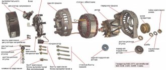
Welding inverter device
Depending on the model, welding inverters operate both from a household electrical network (220 V) and from three-phase (380 V). The only thing that needs to be taken into account when connecting the device to a household network is its power consumption. If it exceeds the capabilities of the electrical wiring, then the unit will not operate if the network is drained.
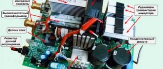
So, the inverter welding machine includes the following main modules.
- Primary rectifier unit. This block, consisting of a diode bridge, is located at the input of the entire electrical circuit of the device. It is this that is supplied with alternating voltage from the mains. To reduce the heating of the rectifier, a heat sink is attached to it. The latter is cooled by a fan (supply fan) installed inside the unit housing. The diode bridge also has overheating protection. It is implemented using a temperature sensor, which breaks the circuit when the diodes reach a temperature of 90°.
- Capacitor filter. It is connected in parallel to the diode bridge to smooth out alternating current ripples and contains 2 capacitors. Each electrolyte has a voltage reserve of at least 400 V, and a capacity of 470 μF for each capacitor.
- Filter for noise suppression. During current conversion processes, electromagnetic interference occurs in the inverter, which can disrupt the operation of other devices connected to this electrical network. To remove interference, a filter is installed in front of the rectifier.
- Inverter. Responsible for converting AC voltage to DC. Converters operating in inverters can be of two types: push-pull half-bridge and full bridge. Below is a diagram of a half-bridge converter with 2 transistor switches, based on devices of the MOSFET or IGBT series, which can most often be seen on inverter devices of the middle price category.
The circuit of a full bridge converter is more complex and already includes 4 transistors. These types of converters are installed on the most powerful welding machines and, accordingly, on the most expensive ones.Just like diodes, transistors are installed on radiators for better heat removal from them. To protect the transistor unit from voltage surges, an RC filter is installed in front of it.
- High frequency transformer. It is installed after the inverter and reduces the high-frequency voltage to 60-70 V. Thanks to the inclusion of a ferrite magnetic core in the design of this module, it is possible to reduce the weight and dimensions of the transformer, as well as reduce power losses and increase the efficiency of the equipment as a whole. For example, the weight of a transformer that has an iron magnetic core and is capable of providing a current of 160 A will be about 18 kg. But a transformer with a ferrite magnetic core with the same current characteristics will have a mass of about 0.3 kg.
- Secondary output rectifier. It consists of a bridge that contains special diodes that respond to high-frequency current at high speed (opening, closing and recovery takes about 50 nanoseconds), which conventional diodes are not capable of. The bridge is equipped with radiators that prevent it from overheating. The rectifier also has protection against voltage surges, implemented in the form of an RC filter. At the output of the module there are two copper terminals, which ensure reliable connection of the power cable and ground cable to them.
- Control board. All operations of the inverter are controlled by a microprocessor, which receives information and controls the operation of the device using various sensors located in almost all components of the unit. Thanks to microprocessor control, ideal current parameters are selected for welding various types of metals. Electronic control also allows you to save energy by supplying precisely calculated and dosed loads.
- Soft start relay. To prevent the rectifier diodes from burning out from the high current of charged capacitors during startup of the inverter, a soft start relay is used.
Spontaneous shutdown
In some cases, repairs can be carried out independently if the device begins to turn off spontaneously. Most models of welding machines are equipped with a protective circuit (automatic) that is triggered in a critical situation, accompanied by a deviation from normal operation. One of the options for such protection involves blocking the operation of the device when the ventilation module is turned off.
After spontaneous shutdown of the welding machine, first of all, you should check the state of the protection and try to return this element to working condition.
If the protective unit is triggered again, it is necessary to proceed to troubleshooting using one of the methods described above related to short circuits or malfunctions of individual parts.
In this situation, first of all, you should make sure that the cooling unit of the unit is working normally and that overheating of the internal spaces is excluded.
It also happens that the cooling unit does not cope with its functions due to the fact that the welding machine was under a load for a long time that exceeded the permissible norm. The only correct solution in this case is to let it “rest” for about 30-40 minutes, and then try to turn it on again.
In the absence of internal protection, a circuit breaker can be installed in the electrical panel. To maintain normal functioning of the welding unit, its settings must correspond to the selected modes.
Thus, some models of such devices (welding inverter, in particular), in accordance with the instructions, must work according to a schedule that requires a break of 3-4 minutes after 7-8 minutes of continuous welding.
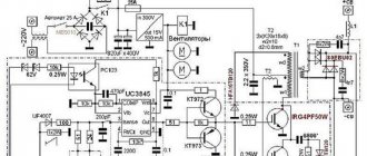
How does an inverter work?
Below is a diagram that clearly shows the principle of operation of a welding inverter.
So, the operating principle of this welding machine module is as follows. The primary rectifier of the inverter receives voltage from the household electrical network or from generators, gasoline or diesel. The incoming current is alternating, but when passing through the diode block it becomes constant. The rectified current is supplied to the inverter, where it is converted back into alternating current, but with changed frequency characteristics, that is, it becomes high-frequency. Next, the high-frequency voltage is lowered by a transformer to 60-70 V with a simultaneous increase in current. At the next stage, the current again enters the rectifier, where it is converted into direct current, after which it is supplied to the output terminals of the unit. All current conversions are controlled by a microprocessor control unit.
Electrode sticking (arc interruption)
The cause of electrode sticking and arc interruption may be a decrease in voltage due to a short circuit in the transformer windings, faulty diodes or loose connecting contacts. A breakdown of the capacitor filter or short circuit of individual parts to the body of the welding machine is also possible.
Organizational reasons due to which the machine does not weld as it should include the excessive length of welding wires (more than 30 meters).
If sticking is accompanied by a strong hum from the transformer, this also indicates an overload in the load circuits of the device or a short circuit in the welding wires.
One of the repair options to eliminate these effects could be restoring the insulation of connecting cables, as well as tightening loose contacts and terminal blocks.
Causes of inverter failures
Modern inverters, especially those made on the basis of an IGBT module, are quite demanding in terms of operating rules. This is explained by the fact that when the unit operates, its internal modules generate a lot of heat. Although radiators and a fan are used to remove heat from power components and electronic boards, these measures are sometimes not enough, especially in inexpensive units. Therefore, you need to strictly follow the rules that are indicated in the instructions for the device, which imply periodically turning off the unit to cool down.
This rule is usually called “On Duration” (DS), which is measured as a percentage. Without observing the PV, the main components of the device overheat and fail. If this happens to a new unit, then this breakdown is not subject to warranty repair.
Also, if an inverter welding machine operates in dusty rooms, dust settles on its radiators and interferes with normal heat transfer, which inevitably leads to overheating and breakdown of electrical components. If the presence of dust in the air cannot be eliminated, it is necessary to open the inverter housing more often and clean all components of the device from accumulated contaminants.
But most often inverters fail when they operate at low temperatures. Breakdowns occur due to the appearance of condensation on the heated control board, resulting in a short circuit between the parts of this electronic module.
Why remake the device?
Now you know that the question “So which current is better: alternating or constant?” has no answer. Devices on a break and devices on a permanent basis are two different phenomena with their own advantages and disadvantages. And ideally, it is better to have in your arsenal universal equipment that can cook with both direct and alternating current.
There are such devices on sale, but they are incomparably expensive. If you are a professional, then it makes sense to buy such a device. But if you are an amateur and cook a couple of times a year at your dacha or in the garage, then it is better to purchase a transformer device and modify it a little. A transformer operating on alternating current can be equipped with the ability to switch to direct current. This way you will get an inexpensive universal device, which will also be powerful and reliable.
Repair features
A distinctive feature of inverters is the presence of an electronic control board, so only a qualified specialist can diagnose and repair faults in this unit . In addition, diode bridges, transistor units, transformers and other parts of the electrical circuit of the device may fail. To carry out diagnostics yourself, you need to have certain knowledge and skills in working with measuring instruments such as an oscilloscope and a multimeter.
From the above, it becomes clear that, without the necessary skills and knowledge, it is not recommended to start repairing the device, especially electronics. Otherwise, it can be completely damaged, and repairing the welding inverter will cost half the cost of a new unit.
Frequent malfunctions
The main manifestations of problems with electric arc welding machines are:
- the device does not turn on when connected to the mains and started;
- sticking of the electrode with a simultaneous hum in the area of the converter;
- spontaneous shutdown of the welding machine in case of overheating.
Repairs always begin with an inspection of the welding machine and checking the supply voltage. Repairing transformer welding machines is not difficult, and they are not picky about maintenance. With inverter devices, it is more difficult to determine a breakdown, and repairs at home are often impossible.
However, if handled properly, inverters last a long time and do not break down. It is necessary to protect from dust, high humidity, frost, and store in a dry place. There are the most typical malfunctions of welding machines that you can fix yourself.
Main malfunctions of the unit and their diagnostics
As already mentioned, inverters fail due to the impact of external factors on the “vital” units of the device. Also, malfunctions of the welding inverter can occur due to improper operation of the equipment or errors in its settings. The most common malfunctions or interruptions in the operation of inverters are:
The device does not turn on
Very often this breakdown is caused by a faulty network cable of the device. Therefore, you first need to remove the casing from the unit and ring each cable wire with a tester. But if everything is in order with the cable, then more serious diagnostics of the inverter will be required. Perhaps the problem lies in the standby power supply of the device. The method of repairing the “duty room” using the example of a Resanta brand inverter is shown in this video.
Welding arc instability or metal spattering
This malfunction may be caused by incorrect current setting for a certain electrode diameter.
Advice! If there are no recommended current values on the packaging for the electrodes, then it can be calculated using the following formula: for each millimeter of equipment there should be a welding current in the range of 20-40 A.
Welding speed should also be taken into account. The smaller it is, the lower the current value must be set on the control panel of the unit. In addition, to ensure that the current strength corresponds to the diameter of the additive, you can use the table below.
Welding current is not adjustable
If the welding current is not regulated, the cause may be a breakdown of the regulator or a violation of the contacts of the wires connected to it. It is necessary to remove the unit casing and check the reliability of the conductor connections, and, if necessary, test the regulator with a multimeter. If everything is in order with it, then this breakdown can be caused by a short circuit in the inductor or a malfunction of the secondary transformer, which will need to be checked with a multimeter. If a malfunction is detected in these modules, they must be replaced or rewound by a specialist.
High power consumption
Excessive power consumption, even if the device is without load, most often causes an interturn short circuit in one of the transformers. In this case, you will not be able to repair them yourself. You need to take the transformer to a mechanic to rewind it.
The electrode sticks to the metal
This happens if the network voltage drops. To get rid of the electrode sticking to the parts being welded, you will need to correctly select and configure the welding mode (according to the instructions for the device). Also, the voltage in the network may sags if the device is connected to an extension cord with a small wire cross-section (less than 2.5 mm2).
Often, a drop in voltage causing electrode sticking occurs when using a power extension cord that is too long. In this case, the problem is solved by connecting the inverter to the generator.
Overheat light on
If the indicator is on, this indicates overheating of the main modules of the unit. The device may also turn off spontaneously, which indicates that the thermal protection has tripped. To prevent these interruptions in the operation of the unit from occurring in the future, it is again necessary to adhere to the correct duty cycle (ST). For example, if duty cycle = 70%, then the device should operate in the following mode: after 7 minutes of operation, the unit will be given 3 minutes to cool down.
In fact, there can be quite a lot of different breakdowns and the reasons that cause them, and it’s difficult to list them all. Therefore, it is better to immediately understand what algorithm is used to diagnose a welding inverter in search of faults. You can learn how to diagnose the device by watching the following training video.
The device does not start
In this case, first of all, you need to make sure that there is voltage in the network and the integrity of the fuses installed in the transformer windings. If they are in good condition, you should use a tester to ring the current windings and each of the rectifier diodes, thereby checking their performance.
If one of the current windings breaks, it will need to be rewinded, and if both are faulty, it is easier to replace the entire transformer. The damaged or “suspicious” diode is replaced with a new one. After repair, the welding machine is turned on again and checked for serviceability.
Sometimes the filter capacitor fails. In this case, the repair will consist of checking it and replacing it with a new part.
If all elements of the circuit are in working order, it is necessary to deal with the mains voltage, which can be greatly underestimated and is simply not enough for the normal functioning of the welding machine.
Recommendations
As you can see, troubleshooting inverter equipment often encounters serious difficulties. However, there are a number of points that can reduce the risk of failure itself. A danger to the welding inverter is its poor resistance to dust. You need to disassemble the device and clean it at least once every 5-6 months. For cleaning, use either soft bristle brushes or compressed air.
Penetration of water , both liquid and condensed from the air, also poses a serious risk. Inexpensive inverters are susceptible to cooling system failures, which prevent emergency shutdown units from working and lead to plastic melting. It is also important to protect the device from voltage drops of more than 190 V. A rise in voltage above the norm is also dangerous, although less than its insufficient level. The risk is also associated with:
- overload due to overly complex and voluminous work;
- falls;
- strong blows;
- poor pad fastening;
- use of low-quality spare parts;
- excessive heating or hypothermia.
It is worth considering recommendations for identifying major defects in the operation of the inverter . If electrode sticking is caused by low voltage in the network, then there are simply no ways to combat this that do not affect the voltage itself.
Sometimes this effect is caused by the fact that the cable inserts are not fixed in the sockets on the panel.
Then they need to be tightened by rotating clockwise. The electrode will also stick if:
- The diameter of the supply wire is less than 2.5 square meters. mm (decided by using a larger wire);
- contacts start to burn;
- An extension cord of more than 40 m is used.
Lack of access to the welding mode, despite a stable network connection and a working connection indicator, is another common problem. In this case, three reasons can be assumed:
- broken cables;
- complete lack of contact;
- Insufficiently tight contact.
Sometimes the voltage goes out during the welding process. This indicates either a malfunction of the automatic regulator, or that it does not match the voltage being used. The overheat indicator will light up whenever critical parts of the device reach a temperature of 80 degrees. The only thing the user can do in such a situation is to wait for natural cooling.
Trying to interfere with the operation of the automation or change its settings is extremely dangerous!
It is worth considering when repairing an inverter that if the transistors fail, then most likely the same fate befell the drive circuit (the same one that is sometimes called the driver). All components of this circuit must be checked immediately. When inspecting a printed circuit board with automation, you must carefully check that there are no burnt areas or breaks on it. All problem areas with such deviations are carefully cleaned and the jumpers are soldered again. Important: burnt out, worn out or torn wires can only be replaced with ones of similar cross-section (provided that this cross-section is sufficient for normal operation).
Trying to correct the current-voltage characteristic does not make much sense. Only trained specialists can do this. What will be required is not reprogramming (this is impossible with budget analog devices), but replacement of the main components with digital units. Therefore, you will have to know perfectly the circuitry and operating features of devices at a low level. But even with a low level of qualification, it is worth working to prevent overheating, which is typical for low-cost products.
First of all, care is taken to ensure that the generated heat is properly removed. Its removal is usually especially poorly organized from power switches and diodes of rectifying circuits. Therefore, it is advisable to take maximum care to increase the airflow. Some inverters do not have fans at all, while in others the ventilation devices are not powerful or sophisticated enough. “Original” coolers almost always have to be dismantled and replaced with 3-4 devices identical in blade span and other parameters.
Collecting coolers in a “stack” is not too easy, and it is not necessary. It’s quite possible to tighten them with screws and calm down. If there is not enough space inside for a large assembly, you can install a 1-channel high-power fan outside.
It is strictly forbidden to use components of dubious origin. Only officially supplied devices and parts will do the job.
Heat dissipation can be improved by changing not only fans, but also radiators. Traditional pre-installed radiators are not always efficient enough. Mica and rubber delimiters separating the device from the flanges must be preserved. When trimming the ribs, you should carefully refine them with a file to remove even small burrs. If this is not done, you will have to constantly deal with the accumulation of dust.
For information about repairing a welding inverter with your own hands, see below.
Pros and cons of inverter welding
Inverter devices show efficiency in the range of 85 - 95%, I must say that this is a high figure among electronic equipment. The circuit used allows you to adjust the level of welding current from several amperes to hundreds, or even thousands.
For example, an inverter of the MMA brand, it is 20 - 220 A. Inverters can operate for a long time. The power supply can be controlled remotely. The undoubted advantages of inverters include their small size and weight characteristics, which allow the device to be moved at the welding site. The design of the devices uses double insulation, ensuring electrical safety.
Technological advantages
The use of inverters allows the use of electrodes of any brand that work with both direct and alternating current. Devices of this type can be used for welding with a non-consumable electrode in a shielding gas environment. In addition, the design of this equipment makes it easy to automate welding processes.
Tungsten electrodes for argon arc welding
Electrodes for resistance welding
Welding can be performed using a short arc, thus reducing energy losses and increasing the quality of the weld; in particular, there is virtually no welding spatter on the surface of the parts being welded. By the way, the use of inverters allows you to produce seams in any spatial configuration.
Microprocessor
Microprocessors are used to control modern welding inverters, and this ensures a stable connection between voltage and current.
Disadvantages of inverters
Inverters are somewhat more difficult to repair than traditional transformer units. If some control elements located on the board fail, repairs can cost about a third of the cost of a new welding inverter.
Inverters, unlike other types of equipment, are very susceptible to dust. That is, such devices must be serviced more often. Operation of an inverter welding machine is also limited by low temperatures. In addition, there are some restrictions on storing the inverter at sub-zero temperatures. This is fraught with the formation of condensation, which can lead to a short circuit on the board.
How to repair an inverter device yourself
If after testing it becomes clear that the cause of malfunctions in the operation of the inverter device lies in its internal part, you should disassemble the case and begin to inspect the electronic filling. It is quite possible that the reason lies in poor-quality soldering of the device parts or poorly connected wires.
A careful inspection of electronic circuits will reveal faulty parts that may be darkened, cracked, with a swollen case or have burnt contacts.
Burnt parts on the Fubac IN-160 inverter board (AC-DC regulator, 2NK90 transistor, 47 Ohm resistor)
During repairs, such parts must be desoldered from the boards (it is advisable to use a soldering iron with suction for this), and then replaced with similar ones. If the markings on faulty elements are not readable, then special tables can be used to select them. After replacing faulty parts, it is advisable to test the electronic boards using a tester. This is especially necessary if the inspection did not reveal elements that need to be repaired.
Visual inspection of the electronic circuits of the inverter and their analysis using a tester should begin with the power unit with transistors, since it is this that is the most vulnerable. If the transistors are faulty, then most likely the circuit that drives them (driver) has also failed. The elements that make up such a circuit also need to be checked first.
Inverter power unit
After checking the transistor block, all other blocks are checked, for which a tester is also used. The surface of printed circuit boards must be carefully inspected to determine the presence of burnt areas and breaks. If any are found, then you should thoroughly clean such places and solder jumpers on them.
If burnt or torn wires are found in the inverter filling, then during repairs they must be replaced with similar cross-sections. Although the diode bridges of the inverter rectifiers are quite reliable elements, they should also be tested using a tester.