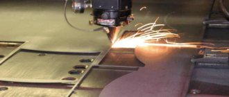
Good day to all! In this lesson we will create an assembly drawing of a metal structure, the assembly of which we completed in the lesson: “Creating an assembly from a metal structure in SolidWorks.”
In general, you should have this assembly open.
Assembling metal structures in SolidWorks
If you don’t have it, you can download it at the end of this lesson: Welding structure in SolidWorks part 2.
Assigning material to assembly parts.
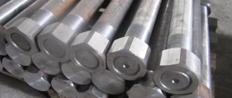
We start with assigning the material; to do this, in the design tree, right-click on the part “3DDD.001.01.005 Brace” .
Menu for selecting material in an assembly in SolidWorks
In the menu that opens, go to the “Material” line, click on “Edit material”. The material assignment window opens.
Material selection window in SolidWorks
Select “Steel 3 GOST 535-88” and click apply. As we can see from the color of the parts in the assembly, a different material was applied to them.
Changed material for braces on an assembly in SolidWorks
Let me remind you that if you do not have a GOST material database installed, you can find out how to do this on this page: Adding a GOST material database to SolidWorks.
Next, we assign the material Steel 3 GOST 535-88 for the remaining parts of the assembly.
Material assigned to all assembly parts
After assigning a material to all parts, you need to fill in the assembly properties.
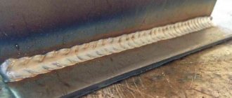
Types of seams according to GOST standards (squares 2 and 3 examples)
Possible methods of connecting two elements are closely discussed in GOSTs 14771-76 and 5264-80. There are the following types of welding joints:
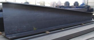
- C – butt weld . The two elements being connected are in the same plane and at the same level. They are connected to each other by adjacent ends. This is one of the most popular connection options. Its peculiarity lies in the fact that the mechanical characteristics of the weld are very high, and the appearance of the finished structure is aesthetic. Along with the positive aspects, there are also negative ones. This type of connection remains technically difficult. It can only be performed qualitatively by experienced specialists.
- T – tee seam . This implies a connection of two elements located at an angle of 90 degrees relative to each other, and the junction has a T-shaped configuration. This is the most rigid connection option of all those considered. Therefore, it is not used in cases where some elasticity is important for the finished structure.
- N – lap seam . Two workpieces are located parallel, but not in the same plane. They are in contact with some overlap of the plane. A fairly strong and reliable connection method, but in terms of rigidity it is inferior to the T-type version.
- U – fillet weld . The ends of two workpieces are positioned at an angle of 90 degrees. The ends melt, resulting in a fairly strong and rigid connection.
- O – special types . This designates all other options for welding workpieces that are not described in the standard.
Both GOST standards mentioned at the beginning of the section have common features and overlap with each other. For manual arc connection according to GOST 5264-80:
- C1 – C40 butt;
- U1 – U10 corner;
- H1 – H2 overlap;
- T1 – T9 tee.
Performing welding work in an inert environment in accordance with GOST 14771-76:
- U1 – U10 corner;
- C1 – C27 butt;
- H1 – H4 overlap;
- T1 – T10 tee.
The example above contains the numbers just discussed. The second square contains information on the standard used - 14771-76. The third square describes the connection method - double-sided T-joint without beveled edges.
Assembly Properties in SolidWorks
To fill in the properties, click on the file properties icon...
File properties icon in SolidWorks
A window opens to fill in the properties. Fill in the properties on the “Configuration” . We enter the designation: “3DDD.001.01.000 SB” , and the name: “Frame” .
Assembly Properties in SolidWorks
Also at the end of the properties window, enter the properties in the format line: “A3” .
Proceed to create an assembly drawing.
9.3. Applying dimensions
Dimensioning is the most critical part of working on a drawing, since incorrectly placed and extra dimensions lead to defects, and lack of dimensions causes production delays. Below are some recommendations for applying dimensions when drawing parts.
The dimensions of the part are measured using a meter on the drawing of the general view of the assembly unit, taking into account the scale of the drawing (with an accuracy of 0.5 mm). When measuring the largest thread diameter, it is necessary to round it to the nearest standard, taken from the reference book. For example, if the diameter of a metric thread is measured to be d = 5.5 mm, then it is necessary to accept an M6 thread (GOST 8878-75).
9.3.1. Size classification
All sizes are divided into two groups: basic (conjugate) and free.
The main dimensions are included in the dimensional chains and determine the relative position of the part in the assembly; they must ensure:
- location of the part in the assembly;
- precision of interaction of assembled parts;
- assembly and disassembly of the product;
- interchangeability of parts.
An example is the dimensions of the female and male elements of mating parts (Figure 9.2). The common contacting surfaces of the two parts have the same nominal size.
Free dimensions are not included in the dimensional chains of the part. These dimensions determine those surfaces of the part that do not connect with the surfaces of other parts, and therefore they are made with less accuracy (Figure 9.2).
A – covering surface; B – covered surface; B - free surface; d – nominal size Figure 9.2
9.3.2. Dimensioning methods
The following sizing methods are used:
- chain;
- coordinate;
- combined.
With the chain method (Figure 9.3), the dimensions are placed sequentially one after another. With this sizing, each roller step is processed independently, and the technological base has its own position. At the same time, the accuracy of the size of each element of the part is not affected by errors in the execution of previous dimensions. However, the total size error consists of the sum of the errors of all sizes. Drawing dimensions in the form of a closed chain is not permitted, except in cases where one of the dimensions of the chain is indicated as a reference. Reference dimensions in the drawing are marked * and written in the field: “* Dimensions for reference ” (Figure 9.4).
Figure 9.3
Figure 9.4
With the coordinate method, dimensions are set from selected bases (Figure 9.5). With this method, there is no summation of sizes and errors in the location of any element relative to one base, which is its advantage.
Figure 9.5
The combined sizing method is a combination of chain and coordinate methods (Figure 9.6). It is used when high precision is required in the manufacture of individual elements of a part.
Figure 9.6
According to their purpose, dimensions are divided into overall, connecting, installation and structural.
Overall dimensions determine the maximum external (or internal) outlines of the product. They are not always applied, but are often listed for reference, especially for large cast parts. The overall dimensions are not applied to bolts and studs.
Connecting and installation dimensions determine the dimensions of the elements by which this product is installed at the installation site or connected to another. These dimensions include: the height of the center of the bearing from the plane of the base; distance between hole centers; diameter of the circle of centers (Figure 9.7).
A group of dimensions that determine the geometry of individual elements of a part intended to perform a particular function, and a group of dimensions for elements of a part, such as chamfers, grooves (the presence of which is caused by processing or assembly technology), are performed with varying accuracy, therefore their dimensions are not included in one dimensional chain (Figure 9.8, a, b).
Figure 9.7
| Wrong | Right |
Figure 9.8, a
| Wrong | Right |
Figure 9.8, b
Creating a drawing from an assembly.
To create a drawing, click: “File, create drawing from assembly” . Select a template for the drawing and sheet format “A3-SPECIFICATION-L1-G” .
Sheet format for creating a SolidWorks assembly drawing
These drawing format templates for SolidWorks according to GOST are available.
And click OK. The drawing sheet opened.
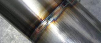
Welding methods (square 4)
The standardization requirements also describe welding methods. The most common of them are:
- A – automatic. It is carried out using flux, but without gaskets and pillows;
- AF is also automatic. But in this case, on the pillow;
- IN – performed in an inert environment using a tungsten electrode without additives;
- INp is the same method as the previous one with the only difference being that additives are used;
- IP – metal connection is carried out in an inert environment using a consumable electrode;
- UP is the same as IP, only carbon dioxide is used instead of an inert medium.
In this case, the fourth square contains the UP symbols. This means that welding was performed in a carbon dioxide environment with consumable electrodes.
Adding views to a drawing.
We add the “Front” view as the main view, and add the “Top” view as the projection view.
We also add auxiliary views using “Local View” and “Section” and Trimetry.
Drawing Views in SolidWorks
Next, add welds to the drawing.
Types of welding seams
First of all, we need to define another important abbreviation - ESDC. This is a Unified System of Design Documentation, which includes a full range of different standards. They regulate the procedure for the execution of technical drawings, including documentation for welding work.
The system also includes the standards that interest us:
- GOST 2.312-72 . Conventional display options and designations of welding seams in the drawings are prescribed.
- GOST 5264-80 . Comprehensive information is provided on all types of welded joints and seams made by manual arc welding.
- GOST 14771-76 . Detailed information about welding in an inert environment; types of seams and joints obtained under such conditions.
Before studying in detail the examples of designations in the drawings, you need to work out information about their types. This is best done in practice. Let the following image be displayed on the drawing:
A jumble of numbers and incomprehensible symbols does not add optimism in any way. But in reality, not everything is so sad. In fact, such a long line contains a logical chain that is not at all difficult to understand. First you need to break the expression into its component blocks:
It's time to look at all the components, divided into squares:
- an auxiliary symbol that informs a specialist about the type of joint: a closed line or an installation connection;
- number of the standard according to which the symbols are given here;
- letter or number designation of the type of connection with all structural elements;
- method of performing welding work in accordance with the standard;
- type of structural element and its dimensions;
- length of continuous section;
- symbol characterizing the type of connection;
- description of the connection using auxiliary symbols.
Next, we will consider each of the elements of the symbol separately. the first square shows an oval, which symbolizes a circular connection. Its alternative is a checkbox that informs about the installation type of the joint. A one-way arrow indicates the suture line. A specific feature is associated with it, which is expressed in the presence of a shelf. Often on graphic drawings you can see the following sign:
Visually, it is similar to the square root symbol from the field of mathematics. The shelf visible in the figure is a field for placing various symbols about the characteristics of the suture line.
If the information is located under the so-called “shelf”, then this indicates that the weld is located on the back side and is invisible from the front. How do you determine which side is considered front and which side is considered back? With a one-way connection, this is easy to do. The front side will be the side you need to work with. But in a double-sided connection with unequal edges, the front side is considered to be the side on which the main welding joint is located. With identical edges, either side can be front or back.
Below is a table with the most commonly used symbols in drawings and their meanings:
Dimensions for a weldment assembly in SolidWorks
We won’t dwell on the sizes separately; I put them as in the picture below. All dimensions are in the main view and top view.
Dimensions on an assembly drawing of a welded structure in SolidWorks
Next, we just need to add part numbers and specifications. Let's start with the numbers.
Examples of symbols
To make it clearer for you and you can quickly understand all the notations, we will give several simple and illustrative examples. So, let's begin.
Example No. 1
In the picture above you see a butt seam in which one edge has a curved bevel. The connection itself is double-sided, made by manual arc welding. There is no gain on either side. On the front side the seam roughness is Rz 20 µm, and on the back side it is Rz 80 µm.
Example No. 2
Here you can see that the seam is corner and double-sided, it has no bevels or edges. This connection is made by automatic welding and using flux.
Example No. 3
Here we have a butt seam again, but without bevels or edges. The connection is one-sided, with a lining. The seam is made using heated gas and welding wire.
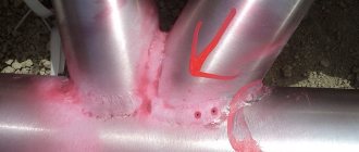
Example No. 4
In the fourth example, the seam is a T-joint and has no bevels or edges. It is intermittent and performed using a bilateral method. The seam seems to be in a checkerboard pattern. The work was performed using RDS in a gas environment and using a non-consumable metal rod. The leg of the seam is 6 millimeters, and the length of the seam is 50 millimeters, in increments of 100 millimeters (indicated by the letter “Z”). t w is the length of the seam, and t pr is the length of the step of the intermittent connection.
Example No. 5
In our last example, the seam is overlapped and has no bevels or edges. It is also single-sided and is performed by manual gas-shielded arc welding using a consumable rod. The welded connection is made along an open line. The leg of the seam is 5 millimeters.
Position numbers on an assembly drawing in SolidWorks
We will put all position numbers on the main view.
Positions on the main view of a weldment structure in SolidWorks
More details about the positions of adding specifications in the lesson: Assembly drawing of a crank-rocker mechanism in SolidWorks, part 2.
9.1. The concept of types of products and design documents
A product is any item or set of production items to be manufactured at an enterprise.
GOST 2.101-88* establishes the following types of products:
- Details;
- Assembly units;
- Complexes;
- Kits.
When studying the Engineering Graphics course, two types of products are offered for consideration: parts and assembly units.
A part is a product made from a material that is homogeneous by name and brand, without the use of assembly operations.
For example: a bushing, a cast body, a rubber cuff (unreinforced), a piece of cable or wire of a given length. Parts also include products that have been coated (protective or decorative), or manufactured using local welding, soldering, and gluing. For example: a body covered with enamel; chrome-plated steel screw; a box glued together from one sheet of cardboard, etc.
Assembly unit is a product consisting of two or more component parts connected to each other at the manufacturer by assembly operations (screwing, welding, soldering, riveting, flaring, gluing, etc.). For example: machine tool, gearbox, welded body, etc.
Complexes are two or more specified products not connected at the manufacturing plant by assembly operations, but intended to perform interrelated operational functions, for example, an automatic telephone exchange, an anti-aircraft complex, etc.
Kits are two or more specified products that are not connected at the manufacturing plant by assembly operations and represent a set of products that have a general operational purpose of an auxiliary nature, for example, a set of spare parts, a set of tools and accessories, a set of measuring equipment, etc.
The production of any product begins with the development of design documentation. Based on the technical specifications, the design organization develops a preliminary design containing the necessary drawings of the future product, an explanatory note, and analyzes the novelty of the product, taking into account the technical capabilities of the enterprise and the economic feasibility of its implementation.
The preliminary design serves as the basis for the development of working design documentation. A complete set of design documentation determines the composition of the product, its structure, the interaction of its components, the design and material of all its parts and other data necessary for the assembly, manufacture and control of the product as a whole.
Assembly drawing is a document containing an image of an assembly unit and the data necessary for its assembly and control.
A general drawing is a document that defines the design of a product, the interaction of its components and the principle of operation of the product.
Specification is a document defining the composition of an assembly unit.
The general drawing has the assembly unit number and SB code.
For example: assembly unit code (Figure 9.1) TM.0004ХХ.100 SB the same number, but without a code, has a specification (Figure 9.2) of this assembly unit. Each product included in the assembly unit has its own position number indicated on the general view drawing. By the position number in the drawing you can find in the specification the name, designation of this part, as well as the quantity. In addition, the note may indicate the material from which the part is made.
9.9. Making a gear drawing
A gear is an important component of many designs of devices and mechanisms designed to transmit or transform motion.
The main elements of a gear wheel: hub, disk, ring gear (Figure 9.16).
Figure 9.16 — Gear elements
The tooth profiles are normalized by the relevant standards.
The main parameters of the gear are (Figure 9.17): m=P t
/ π [
mm
] – module;
d a
=
m st
(
Z
+2) – diameter of the circle of the tops of the teeth;
d
=
m st Z
– pitch diameter;
d f
=
m st
(
Z
– 2.5) – diameter of the circle of the depressions;
S t
= 0.5 m
st
π – tooth width; ha – height of the tooth head; hf – height of the tooth stem; h = ha+hf – tooth height; Pt – dividing circumferential step.
Figure 9.17 — Gear parameters
The main characteristic of the ring gear is the modulus - a coefficient that relates the circumferential pitch to the number π.
The module is standardized (GOST 9563-80). m = Pt / π [mm] Table 9.1 - Basic norms of interchangeability. Gear wheels. Modules, mm
| 0,25 | (0,7) | (1,75) | 3 | (5,5) | 10 | (18) | 32 |
| 0,3 | 0,8; (0,9) | 2 | (3,5) | 6 | (11) | 20 | (36) |
| 0,4 | 1; (1,125) | (2,25) | 4 | (7) | 12 | (22) | 40 |
| 0,5 | 1,25 | 2,5 | (4,5) | 8 | (14) | 25 | (45) |
| 0,6 | 1,5 | (2,75) | 5 | (9) | 16 | (28) | 50 |
On educational drawings of gears: Height of the tooth head – ha = m; Height of the tooth stem – hf = 1.25m; Roughness of tooth working surfaces – Ra 0.8 [µm];
At the top right of the sheet, a table of parameters is drawn up, the dimensions of which are shown in Figure 9.18; often only the modulus value, the number of teeth and the pitch diameter are filled in.
Figure 9.18 — Parameter table
Wheel teeth are depicted conventionally, according to GOST 2.402-68 (Figure 9.19). The dashed line is the dividing circle of the wheel.
In the section the tooth is shown uncut.
| A | b | V |
Figure 9.19 - Image of a gear wheel a - in section, b - in front view and c - in left view
The roughness on the lateral working surface of the tooth in the drawing is indicated on the pitch circle. An example of a gear drawing is shown in Figure 9.20.
Figure 9.20 — An example of a training drawing of a gear
9.5. Making a drawing of a part that has the shape of a body of revolution
Parts that have the shape of a body of rotation are found in the vast majority (50-55% of the original parts) in mechanical engineering, because rotational movement is the most common type of movement of elements of existing mechanisms. In addition, such parts are technologically advanced. These include shafts, bushings, disks, etc. processing of such parts is carried out on lathes, where the axis of rotation is located horizontally.
Therefore, parts having the shape of a body of rotation are placed on the drawings so that the axis of rotation is parallel to the main inscription of the drawing (stamp). It is advisable to place the end of the part, taken as the technological base for processing, on the right, i.e. the way it will be positioned during processing on the machine. The working drawing of the bushing (Figure 9.9) shows the execution of a part that is a surface of rotation. The outer and inner surfaces of the part are limited by surfaces of rotation and planes. Another example could be the “Shaft” part (Figure 9.10), limited by coaxial surfaces of rotation. The center line is parallel to the title block. Dimensions are given in a combined way.
Figure 9.9 - Working drawing of a part of the surface of rotation
Figure 9.10 — Working drawing of the “Shaft” part