Here you will learn:
- Where is it installed in the heating system?
- Operating principle of a check valve
- Types of check valve
- Direct and indirect acting valve
- Check valve connection diagrams
- Installation recommendations
One of the mandatory elements of any system is a check valve for heating, which is used in the circuit to regulate the direction of circulation of the coolant. Buyers have access to various models on the market, which differ in method of use and design features. Although most ordinary people have a general understanding of the purpose of a valve in a heating system, this type of fittings performs important functions and helps prevent serious accidents caused by changes in water flow due to pressure surges or airy batteries
.
Where is it installed in the heating system?
The general purpose of a check valve is to allow coolant flow in one direction and prevent it from moving back. They do not require power or any other conditions to operate; they operate from the movement of liquids. A check valve for heating is installed in all positions where backflow and parasitic circuits may occur.
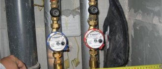
In a heating system with several branches, a check valve is placed on the return pipeline. This prevents the pump from “pushing” the flow in the opposite direction.
The same devices are installed in cold and hot water supply. Those intended for heating are distinguished by the fact that materials are used that can withstand prolonged exposure to elevated temperatures. If there are rubber gaskets, then heat-resistant rubber is used. The same applies to plastic parts.
If we talk specifically about heating systems (HC), then a check valve is installed:
- To a bypass with a circulation pump in the piping of a solid fuel boiler - to ensure operation of the system in gravity mode (with natural circulation). In this case, models with the least resistance are installed, which operate easily and quickly - immediately when a flow from natural circulation appears. The function of the valve, in this case, is not to bypass the coolant when the pump is running.
- On the return pipeline when installing an indirect heating boiler. Why install a check valve in this case? To prevent the flow of coolant in the opposite direction when the circulation pump is operating.
- With a branched heating system (for example, on several floors), on each branch. These check valves prevent the coolant from being “pulled” if one of the branches is turned off (when using one circulation pump).
- On the system's cold water make-up line. Here, in addition to the shut-off valve, a return valve is also needed. Since sometimes the pressure in the water supply is lower than in the heating system. Then, when opening the tap to refuel the system, without a check valve, the coolant will “go” into the water supply system.
Symbol of a check valve in the diagram
In the diagrams, the check valve is designated as two triangles with their vertices directed towards each other. One of the triangles is shaded. The installation location in the branch is almost any. The main thing is that it exists. The direction of flow is indicated by an arrow on the housing. The coolant flows in this direction. In the opposite case, it overlaps. When installing, carefully follow the arrow (you can also focus on the locking element).
Warm floor
You should not trust sources that claim that a heated floor can be laid together with a radiator system and nothing will happen to it. For heated floors, the maximum temperature should be no more than 55C. Therefore, for such a heating circuit, it is best to install a Maybes and Buderus pump group with temperature control (for floor-standing boilers), or a Termex group from Maybes for wall-mounted boilers. These groups are installed on the circuit of heated floors. Installation location - near the boiler, where the decoupling of the heating circuits begins.
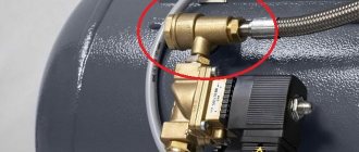
Boiler connection
Connecting a boiler (storage water heater) does not require superpowers. The main thing in this matter is to make connections according to the diagram and to properly seal all connections. Modern automatic boilers have a special connector for connecting and monitoring the operation of the boiler.
Wall-mounted boiler and boiler.
Boiler connection diagram.
Connecting the boiler to a floor-standing boiler.
Operating principle of a check valve
First of all, it should be noted that check valves are not installed “just in case,” but only if necessary, if there is no other technical solution. This is due to the fact that the elements often have considerable hydraulic resistance, depending on the design. This introduces some restrictions when using check valves for heating with natural circulation. The reason is too low coolant pressure in the system.
An exception is gravity valves with a rotary damper; some of their models are capable of opening the path of coolant at a minimum pressure of 0.001 Bar.
Despite the differences in design, most products are equipped with one key part - a spring. It is an actuator that closes the valve when normal conditions change; this is the principle of operation of the check valve. The force expended to overcome the elasticity of the spring determines the magnitude of the hydraulic resistance of the mechanism. For circuits with different operating parameters, products are selected that have the appropriate elasticity and massiveness of the spring.
What does the spring act on? Its task is to keep the locking device closed; this is its normal state. Then the fluid flow flowing from one side can overcome the elastic force of the spring, open the obstacle and move further along the pipe. An attempt to change the direction of the flow and flow in the other direction will lead to nothing - the shut-off device will slam shut, relying on the tide in the body. In this place there is a sealing element that makes the check valve in the heating system completely sealed.
Shut-off valves intended for use in heating circuits are made from the following materials:
- gray cast iron;
- steel;
- brass;
- stainless steel.
CLAIM
1. Ball check valve, comprising a hollow steel cylindrical body with an internal annular protrusion, a valve pair installed in the body, made in the form of an annular seat and a ball locking element, a travel limiter of the locking element in the form of a cage with through holes for liquid flow, fixed in the body cavity using a retaining ring, with the seat installed on one side of the annular protrusion at the valve inlet, and the cage on the other side of the annular protrusion, the seat is secured with a nut and a threaded bushing, characterized in that the internal diameter of the cage exceeds the diameter of the ball by no more than 1.5%, and the depth of the cage ensures the ball moves by no more than one ball diameter, while in the entrance part of the cage its internal diameter is expanded to prevent the ball from jamming when the valve is unlocked.
2. The valve according to claim 1, characterized in that the through holes of the cage are made in steps, so that the diameter of the holes in the bottom part of the cage is smaller than the diameters of the channels connected to them, formed by grooves in the side walls of the cage.
3. The valve according to claim 1, characterized in that the thickness of the inner annular protrusion of the body separating the valve seat and the cage ranges from 0.15 to 2 diameters of the shut-off element ball.
4. The valve according to claim 1, characterized in that the nut and threaded bushing are made with blind key grooves.
5. The valve according to claim 4, characterized in that the nut and threaded bushing are made with at least two key slots, preferably with four key slots.
6. The valve according to claim 1, characterized in that the nut and threaded bushing are made with key holes located at the end of the nut and at the end of the threaded bushing.
7. The valve according to claim 1, characterized in that on the outer side of the threaded bushing there is a protective collar and an annular groove under it to accommodate a seal or O-ring.
8. The valve according to claim 7, characterized in that a seal, preferably an O-ring made of rubber or silicone, is installed in the groove between the threaded bushing and the body.
9. The valve according to claim 1, characterized in that the groove for placing the sealing ring is made on the inside of the neck of the body.
10. The valve according to claim 1, characterized in that the nut, threaded bushing and cage are made of stainless steel.
11. The valve according to claim 1, characterized in that the expansion in the leading part of the cage is made in the form of a groove to a depth approximately equal to half the radius of the ball with an end chamfer, preferably at an angle of 45° and an end chamfer, preferably at an angle of 11°.
12. Ball check valve, comprising a hollow steel cylindrical body with an internal annular protrusion, a valve pair installed in the body, made in the form of an annular seat and a ball locking element, a travel limiter of the locking element in the form of a cage with through holes for the flow of liquid, fixed in the body cavity using a retaining ring, with the seat installed on one side of the annular protrusion at the valve inlet, and the cage on the other side of the annular protrusion, the seat is secured with a nut and a threaded bushing equipped with an O-ring on the outside, characterized in that the inner diameter of the cage exceeds the diameter of the ball by no more than 1.5%, while the depth of the cage ensures that the ball moves by no more than one ball diameter, and in the entrance part of the cage there is an expansion, the diameter of which exceeds the internal diameter of the cage by 5 to 30%, and the nut and threaded bushing are made with blind key grooves without a through groove on their outer side wall or with key holes located at the end of the nut and at the end of the threaded bushing.
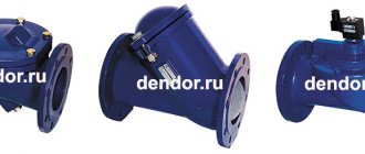
Types of check valve
Despite the fact that all devices of this type perform the same task, they have structural and, therefore, operational differences. Let's take a closer look at each of these types.
Disc valve
A distinctive feature of the product is the presence of a disc valve. This is a plastic or metal element, the dimensions of which allow it to completely block the flow of coolant if it begins to move in the opposite direction.
The disk is connected to a steel spring. When a liquid moves forward, it is in a compressed state. When changing direction, it straightens and moves the disk from its place, thereby blocking the pipe.
The valve design also includes a sealing gasket, which allows the valve mechanism to sit as tightly as possible in the seat. Therefore, leakage is excluded in serviceable devices.
Disc devices are widely used in the design of household heating systems, as they have significant advantages:
- Compactness. The dimensions of the products and their weight are small, which makes it possible to install them on any system.
- The device does not require regular maintenance.
- The cost of the device is low.
Among the significant shortcomings, it is worth noting that it is unsuitable for repair. Therefore, failed valves are immediately replaced with new ones.
A significant disadvantage of disk devices is significant hydraulic resistance. The diagram clearly shows how it arises. The liquid has to overcome an obstacle in the form of a locking disc
And one more minus is the significant hydraulic resistance created by the device. For some systems, such as a geothermal heat pump, this can be critical. Over time, the butterfly valve becomes covered with a layer of mineral deposits, which leads to failure of the device.
Standard butterfly valves create some shock loads when closing. This does not affect their performance and technical condition in any way, but water hammer occurs in the system. Which is not desirable for her.
Disk devices with an additional mechanism that allows closing the hole as smoothly as possible do not have this drawback. Their cost is higher than that of standard analogues.
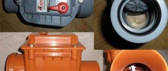
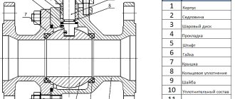
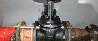
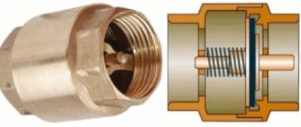
Ball or gravitational
In a gravity check valve for heating systems, the main working element that blocks the flow of water is a metal ball. To improve the fit, the ball is covered with a thin layer of elastic plastic or rubber. When the fluid flows through the device in a given direction, it lifts the ball above the seat with the force of its pressure and opens the lumen.
If the flow pressure drops or the direction of movement of the fluid flow is reversed, the ball, under the influence of gravity, falls onto the saddle, presses against it and blocks the lumen. The more the liquid tries to flow in the opposite direction, the stronger the pressure and the more reliable the overlap.
The advantages of this design are as follows:
- Low flow resistance in open position.
- Maximum reliability. The device does not contain rubbing elements and practically does not wear out in the open position.
- High maintainability. The removable cover makes it easy to clean the chamber and working elements of the device and replace the ball if necessary.
The disadvantages include factors such as:
- Large diameter.
- High operating pressure.
- The need to strictly adhere to the orientation of the device during installation. Otherwise, the ball will not rise and open the gap.
High requirements for installation and operating pressure limit the use of such fittings in home heating systems.
Reed valve
The shutter for this type of valve is a thin steel plate. It is attached to a hinged structure that allows it to move.
The double-leaf type reed check valve is very reliable and can withstand high pressure. But at the same time it exhibits serious hydraulic resistance, since the rotary axis of the valves is located directly in the center of the passage opening
There are two types of petal devices. Single-leaf or rotary are equipped with one plate that can rotate around an axis.
When the coolant moves in a given direction, it lifts the sash, thereby opening the passage hole. When the flow direction changes, the plate lowers. This can be done either with or without a spring.
Butterfly valves are designed slightly differently. They have two locking plates mounted on a rotating axis and located in the center of the passage opening.
The coolant moving along the heating circuit opens both flaps of the double-leaf check valve, and when the direction of its movement changes, the springs slam the plates
The advantages of using these valves are:
- some models of gravity valves can operate without springs, which allows them to be used in gravity systems;
- relatively low cost of devices.
Among the disadvantages, it is worth noting the rather high hydraulic resistance. This is especially true for double-leaf models - the rotary axis is located directly in the center of the passage opening, which is a significant obstacle to moving liquid.
For this reason, butterfly valves are used exclusively in high pressure systems.
Lifting equipment
Lift valves are equipped with a spool that can move freely relative to a vertical axis. On the through hole there is a seat where the spool is located.
When liquid is supplied, the force of its pressure lifts the valve, and it moves along the axis, opening a hole for the movement of coolant. As soon as the flow pressure weakens or it changes its direction, the spool will lower into the seat.
The lift check valve can only be installed vertically. Otherwise, the pressure of the coolant liquid will not be enough to lift the locking mechanism
The advantages of these devices are:
- Reliability. The equipment has a fairly simple design, which allows it to operate with minimal risk of breakdown.
- Low sensitivity to coolant quality.
- Possibility of repairs. For this purpose, a removable cover is located in the upper part of the device body.
Among the disadvantages, installation limitations should be noted. Due to the design features, they can only be mounted in a strictly vertical position.
Rules for choosing a locking device
Choosing a check valve intended for a heating system is a responsible undertaking. If knowledge in this area is minimal, it is best to seek help from specialists. This will ensure that your new heating system is functional and safe.
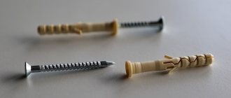
You need to know that, regardless of their type, all check valves differ in the way they are connected to the pipeline.
Sleeve check valves are very easy to install. However, the threaded connection cannot withstand high pressure, so they have limitations in use
Coupling devices are equipped with a connecting threaded unit, which greatly facilitates their connection to the main line. Most often, such a unit is equipped with disc valves intended for installation in autonomous heating systems of an apartment or private house. Their distinguishing feature is their small diameter. Most often it is no larger than DU-50.
Flange products are a structure assembled on the basis of a part that has holes for fastenings. Using the latter, it is connected to the main pipeline. A flange connection is much stronger than a threaded connection.
For this reason, flanged valves are widely used in the construction of large-diameter pipelines. Ball type devices are most in demand.
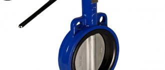
Wafer devices are designed for installation between two pipe flanges. They are lightweight and compact. Very often, both types of reed-type valves are produced in wafer design.
On sale you can find check valves that are installed by welding. This option can be used, for example, when installing heating from polypropylene pipes.
Flanged type check valves are securely attached to the pipe. This connection can withstand high pressure, which allows the devices to be used in centralized pipelines
Another important selection criterion is the material from which the device is made. It could be stainless steel. This option is considered optimal for highways with a diameter of less than 0.04 m.
The metal is practically not subject to corrosion processes and can withstand loads of up to 10 atm. This allows the valve to operate in the system trouble-free and for a very long time, but its cost is quite high. Brass valves have a lower price. They are subject to corrosion, but this process occurs very slowly, which significantly increases their service life.
However, their mechanical strength is much lower than that of stainless steel. Nevertheless, they can withstand the loads that arise in a household network quite easily. The most durable valves are made of cast iron - they successfully cope with critical pressure values, have significant dimensions and impressive weight.
Due to the nature of production, only body parts with a diameter greater than 40 mm can be made of cast iron. For this reason, they are used extremely rarely for the installation of autonomous heating systems.
It is desirable that not only the body, but also all internal elements of the check valve are made of metal. Plastic usually has less strength, which can lead to premature failure of the part.
When choosing a check valve, you need to remember one more rule - its diameter must exactly match the parameters of the passage hole. It is very important that the operating pressure of the system does not exceed the maximum permissible values for operation established by the manufacturer of the selected model.
Direct and indirect acting valve
Pressure control valves are divided into direct and indirect acting devices.
- The first type of valve has a simple design: a spring is driven by a shutter, which is directly pressed by the coolant. Such devices are inexpensive, easy to operate, reliable, insensitive to dirt, but not very accurate in settings.
- Indirect-acting devices, also called pulse devices, have a piston-actuated main valve, a smaller pulse valve, and a pressure transducer. When the pressure changes, the small valve presses on the piston, which moves the main valve, which regulates the throughput of the device. Thus, flow control occurs indirectly, in an indirect way. Valves of this type are less reliable due to the larger number of parts and are expensive, but they can be adjusted more accurately.
Thermal valve
The thermal control valve for a heating radiator is one of the most effective types of fittings. The valve allows you to increase the functionality of the circuit and make the heating process simple, comfortable and rational.
It can be automatic or mechanical. A mechanical thermal valve for heating consists of two main parts. This is a thermal head and valve. The automatic analogue has a more complex design.
An automatic thermal valve is characterized by the presence of the following elements:
- temperature sensor of built-in or remote format; programmer; automatic control system.
An automatic thermal valve regulates the temperature in the circuit according to the settings previously specified by the user. This device has a fairly high cost and allows you to optimize the operation of the system as much as possible.
Check valve connection diagrams
Before using shut-off valves of a certain type in a heating system, you need to understand what function it will perform. To be more specific, there are several possible options for where to install a check valve for heating.
The valves can be mounted on certain circuits in a closed heating system where there are circulation pumps. The main task is to prevent the formation of unpredictable flows of water in unnecessary directions. They can significantly deteriorate the condition of highways and their functionality.
A valve installed on the bypass helps the pump switch to natural circulation mode during a power outage, while being parallel to it. If you install the device in the make-up pipeline, this will avoid emptying the heating network in some situations.
There are common myths that when installing the device in front of the only pump in a single-circuit heating system, you can protect it from water hammer. This is not true, since the direct purpose of the valve is different.
An example is a diagram of the joint connection of a solid fuel and electric boiler. If one pump turns off, the second one will pump water in a small circle, and in this case, shut-off valves are indispensable. The same situation may arise when an indirect heating boiler without a water gun or distribution comb is additionally installed in the radiator connection diagram.
If we are talking about installation on a bypass, then, as a rule, this is typical for gravity systems with natural circulation of water. All of them are converted to work with a pump. If the power goes out, the bypass unit will stop and the natural flow of water will resume.
Installing shut-off valves on the make-up system is not necessary, but can save you from many problems.
Installation recommendations
A check valve is installed to prevent changes in the direction of fluid flow in pipes. It is a mandatory element in heating systems with forced circulation and gravity heating. Installation on the pipe is required before connecting to the boiler pipe. It is mounted after the circulation pump.
In addition, a protective device is installed in the pump piping - on the reserve pipe. This is necessary in case of a power outage or pump failure. In this case, the forced circulation circuit is closed using taps, and the liquid flow is directed into a pipe with a check valve.
Another application option is the arrangement of a heating make-up unit. It is necessary to automatically add water to the main line when its volume or pressure critically decreases. The check valve for this circuit performs protective functions - it prevents the movement of coolant into the water supply system when the pressure in it critically decreases.
The protective device can be used to install underfloor heating systems and mixing units. In some cases, it is recommended to install it in the radiator piping on the bypass. The main thing is that it should not destabilize the operation of the heat supply. To do this, it is necessary to periodically check it, and if its performance deteriorates, repair or replace it.