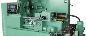
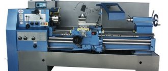
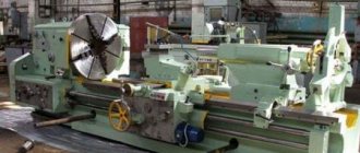
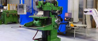
The group of machines for universal use includes horizontal boring machines, models with a vertically or horizontally located spindle, which has at least one axis of freedom. The spindle usually contains:
- mount for cutting tools;
- chuck (drill, countersink, milling cutter, tap, die);
- laser head;
- special fastening, etc.
Horizontal boring machine
The main working surface of a universal machine is the table on which the workpiece or workpiece is fixed. As a general rule, a boring machine is oriented towards single and serial production. But it can be used as a unique tool for fine handwork and as a universal tool for mass production. For each horizontal boring machine, the passport and general description of the model determine:
- what kinematic scheme is used;
- how the electrical circuit is built;
- spindle and work table device;
- pre-processing of the workpiece;
- who are the tool manufacturers?
A review of the original models, as well as cases where the modernization of horizontal boring machines was carried out for the purposes of mass production, does not provide grounds for asserting that even the most complex of them has or can have the required versatility. However, the achieved level of technology meets consumer requirements. For some positions, versatility is achievable across a wide range of parts:
- edge processing;
- drilling holes;
- grinding the treated surface;
- boring the cavity;
- surface milling
The operating principle of this equipment allows automation and versatility of the model in terms of a variety of workpiece options.
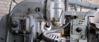
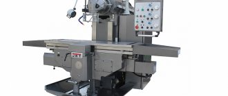
Appearance of horizontal boring machine
Horizontal boring machine W100
Some types of equipment, for example, a horizontal drilling and boring machine, are limited in the functionality of the spindle and work table in the options of actions performed and workpieces, but not all of them are completely deprived of the possibility of external control, that is, use on a conveyor, line serviced by automatic machines (robots), or use in a workshop with general automation of the full production cycle of a specific product.
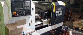
In all cases, especially when a CNC horizontal boring machine is involved, full-scale serial or mass production can be designed.
As a general rule, every universal machine has a multifunctional set of fasteners on its desktop and the maximum possible freedom of the spindle and its modifications (different models, different purposes), attachments, etc.
A machine that processes or manufactures products according to a special program may have two spindles and a multi-purpose work table that moves in three-dimensional space rather than in one plane. There may be several options for installing a working tool, and they may not always have an “official” origin from the manufacturer.
In production, in which processing on horizontal boring machines is the basis of production at the operational site, especially in the serial version, modification of the functionality is a common practice.
If we talk about serious, functionally complete and powerful equipment, then a horizontal boring machine with a rotary table is, first of all, the working surface on which both the spindle of the machine itself and its additional mechanisms, modified mechanisms (cutting, drilling, milling devices...) are oriented. ) or hands (working tools) of nearby robots or other equipment.
Manufacturers imagine a boring machine in different ways. Some make products with a fixed spindle but a movable work table, others give freedom to the front and rear posts, or just the front post, but in two directions. On particularly heavy machines, the work table is a monolithic slab, and the spindle does all the work.
A universal boring machine is a forming machine due to the movement of the spindle and the movement of the work table. The supply of motion can be carried out in various ways, according to various kinematic schemes. In particular, horizontal boring machines, types, models, manufacturers can differ dramatically not only in the method of supplying rotational or translational motion, but also in the production experience and preferences of the manufacturer.
Purpose of the machines
Devices can be used when:
- There is a need for thread cutting (both internal and external);
- Drill blind and through holes;
- Countersinking is carried out;
- The ends of the workpieces are trimmed;
- It is necessary to do face and cylindrical milling.
In most cases, such equipment is used for finishing or semi-finishing. Part bodies are processed extremely rarely, but sometimes such manipulation is carried out. Boring machines are repaired in approximately the same way as lathes. This also applies to operating conditions and rules, because the machines have a similar design.
Like other numerous special types of equipment, the boring machine was designed on the basis of a lathe.
Processing of workpieces on horizontal boring machines
Horizontal boring machines are among the most common; the designs of other universal and special boring machines are based on them.
Rice. 68. Horizontal boring machine
In Fig. 68 shows a horizontal boring machine. On the frame 1 there is a rack 2, on the vertical guides of which a spindle headstock 3 is mounted. The spindle headstock contains a gearbox and a feedbox. The gearbox spindle is hollow; a faceplate 4 with a radial support 5 is attached to it. A boring spindle 6 is mounted inside the hollow spindle. The rear stand with a steady rest 8 is designed to support long boring bars. The rest 8 moves along the rear rack 7 synchronously with the spindle head 3, maintaining alignment with the spindle.
The workpiece is mounted on a rotary table 11, consisting of two parts: a slide 9 moving along the frame, and a carriage 10 having transverse movement. The eye movement is the rotation of the boring spindle or faceplate. The feed movement, depending on the nature of the surfaces being processed, is received by the table (workpiece) or tool due to the axial movement of the boring spindle 6, the radial movement of the support 5 or the vertical movement of the spindle head 3 along the guides of the rack 2.
Boring machines machine holes, external cylindrical and flat surfaces, ledges, grooves, and less often conical holes and cut internal and external threads with cutters. The most common type of processing on boring machines is boring holes.
Boring of cylindrical holes is performed with cutters mounted on a cantilever or two-support mandrel. The use of a cantilever mandrel is advisable in cases where the length of the hole being machined is , since as the length of the mandrel increases, its rigidity decreases.
In Fig. 69, and shows a diagram of boring a small-length hole with a two-edged plate cutter mounted in a cantilever mandrel. The workpiece is given a longitudinal feed. With a short hole length, when it is possible to work with a short rigid mandrel, they are bored with the axial feed of the boring spindle. By boring with longitudinal feed of the workpiece, a more correct hole is obtained due to the constant overhang of the spindle.
Holes with a ratio l/d > 5 and coaxial holes are bored with cutters fixed in a double mandrel.
Rice. 69. Schemes for processing workpieces on horizontal boring machines
In Fig. 69. shows the simultaneous boring of two coaxial holes. The mandrel with cutters receives the main rotational movement, and the workpiece receives longitudinal feed in the direction from the rear stack to the spindle head.
Holes of large diameter, but short length, are bored with a cutter fixed in the radial support of the faceplate (Fig. 69 c). The faceplate with the cutter is given the main rotational movement, and the table with the workpiece is given the longitudinal feed. Holes with a diameter of more than 130 mm are processed with boring blocks and heads.
Boring of parallel and mutually perpendicular holes is performed from one installation of the workpiece. After boring the first hole, move the table in the transverse direction or the spindle head in the vertical direction by an amount equal to the center-to-center distance, then bore the second and other holes. If you need to bore mutually perpendicular holes, then after boring the first hole, turn the table 90° and bore the second hole.
Boring of conical holes is carried out with boring heads mounted in a boring spindle, which is given an axial feed. Conical holes with a diameter of more than 80 mm are bored with a cutter using a universal device mounted on the radial support of the faceplate (Fig. 69, d).
Drilling, countersinking, reaming, counterbore, countersinking and tapping are performed on boring machines in the same way as on vertical drilling machines. The tool is fixed in the boring spindle and the main rotational movement and axial feed are imparted to it. The workpiece placed on the machine table remains motionless.
Cutting the ends is performed in two ways: with the cutter fed in a direction perpendicular or parallel to the spindle axis.
In Fig. 69, d shows cutting the end with a pass-through cutter mounted on the radial support of the faceplate. The cutter, rotating together with the faceplate, is given a radial feed by moving the caliper along the faceplate guides. Small planes are trimmed with a plate cutter (Fig. 69, e), which is given an axial feed by moving the boring spindle. Machining end surfaces with radial feed ensures greater accuracy.
Surface milling is shown in Fig. 69, f. When milling a vertical plane with a face milling head mounted in a boring spindle, the main rotational movement and vertical feed are imparted to the cutter by moving the spindle head.
When using special devices on horizontal boring machines, it is possible to process shaped surfaces and cut threads with cutters.
Equipment types
As a rule, there are three main types used in production:
- Horizontal boring machines;
- Coordinate boring;
- Diamond boring.
The first two types are the most common.
Horizontal boring machines
The main feature of such equipment is the horizontal position of the spindle, which allows it to extend. Thus, it is possible to make a hole even in inaccessible places of large parts (booms, frames, metal structures).
The main movement of the unit is rotational-translational, performed through a spindle. Not only the tools move, but also the workpieces themselves. If the need arises, you can change the feed and speed during operation. Sometimes a special substrate is used when feeding.
Depending on the configuration, there may be additional auxiliary movements:
- The spindle head moves along a vertical axis;
- The table moves along previously specified coordinates.
In some models, the design provides that the rest and rear pillar can move. They can be used for processing products made of cast iron or cast steel.
Boring machines are used to work with complex parts that contain numerous holes, grooves, and ledges. According to their layout they are divided into:
- Models with a spindle no more than 125 mm. Designed for processing small workpieces. The table is movable along two axes, the boring heads move in the vertical direction.
- Models with spindle 100−200 mm. Allows you to work with medium and large parts. The table moves only along one axis.
- Models with spindle 125−320 mm. With their help you can process very large parts. The table is motionless.
Jig boring machines
Such machines are designed for drilling holes according to certain parameters. Perform operations on various workpieces. High-precision processing is obtained due to the presence of special devices: electronic, mechanical and optical. In addition, rotary tables also help to achieve the desired results: the hole can be made without moving the part. The models are not too large and take up little usable space.
Diamond boring type models
They allow fine boring of cylindrical surfaces. If there are additional components, then conical surfaces and ends with rotation grooves can be processed. It is permissible to drill a pair of holes that have parallel axes. Machines of this type can be:
- Vertical;
- Sloping;
- Combined;
- Horizontal, the table is movable.
Jig boring machines
The main feature of jig boring machines (Fig. 3) is the high precision of processing parts.
Figure 3. Jig boring machine.
Figure 3. Jig boring machine.
Increased processing accuracy is achieved through the use of various high-precision mechanisms for calculating the coordinates along which the cutter moves. There are several main methods for calculating coordinates implemented on jig boring machines:
- inductive;
- mechanical;
- optical-mechanical;
- electronic.
The spindle on the machines of this subgroup is located vertically. But sometimes there are models with a horizontal spindle. The spindle head, in addition to changing the speed and direction of rotation, also carries out a working feed, increasing or decreasing the depth of penetration of the cutter into the part.
The table has two degrees of freedom. A part fixed on a table can move in the longitudinal and transverse directions. Moreover, the magnitude of these movements is controlled with high accuracy by the coordinate system.
Also, on jig boring machines, in addition to performing the entire range of operations characteristic of boring group machines, marking operations are performed.
What to pay attention to
Before making a purchase, pay attention to a number of parameters, in particular:
- Spindle dimensions;
- Maximum permissible weight and dimensions of workpieces;
- Desktop diameter;
- The maximum possible level of movement along the axes;
- Speed range;
- Feed interval;
- Engine power.
Engine power is one of the important indicators on which the processing speed of parts will depend.
Boring machines belong to special and sought-after equipment; they are indispensable in many cases, especially when it is necessary to achieve jewelry precision and maximum productivity. If an enterprise is in dire need of mechanisms of this type, it will be able to find suitable options on the domestic market without much effort.
Technical characteristics of the machine 2431
The technical characteristics of the machine 2431 are the main indicator of the machine’s suitability for performing certain jobs. For jig boring machines, the main characteristics are:
- table working surface size
- largest drilling diameter
- largest boring diameter
- spindle overhang
- distance from the end of the spindle to the working surface of the table
- spindle revolutions per minute
Below is a table with the technical characteristics of the jig boring machine 2431. More detailed technical characteristics of the jig boring machine can be found in the passport of the machine 2431
| Quantities | ||
| Accuracy class according to GOST 8-71 | WITH | |
| Table working surface width | mm | 320 |
| Table working surface length | mm | 560 |
| Number of T-slots | 5 | |
| Distance between grooves | mm | 63 |
| Groove width | mm | 12 |
| Maximum longitudinal movement of the table | mm | 400 |
| Maximum lateral movement of the table | mm | 250 |
| Adjusting the table feed | steps | 16 |
| Table feed limits | mm/min | 22…600 |
| Table speed value | mm/min | 1600 |
| Distance from spindle axis to column | mm | 375 |
| The shortest distance from the end of the spindle to the working surface of the table | mm | 120 |
| The greatest distance from the end of the spindle to the working surface of the table | mm | 500 |
| Maximum spindle sleeve stroke | mm | 150 |
| Maximum movement of the spindle head | mm | 230 |
| Number of spindle speed steps | 17 | |
| Spindle speed limits | mm | 75-3000 |
| Number of spindle feed rates | 6 | |
| Spindle feed | mm/rev | 0,02;0,03;0,06;0,08;0,12;0,2 |
| Spindle inner taper | Morse 3 | |
| Outer cone diameter | 60 | |
| Outer cone taper | 7:24 | |
| Largest drilling diameter for steel in solid material | mm | 18 |
| Largest boring diameter | mm | 125 |
| The largest mass of the workpiece | kg | 250 |
| Overall dimensions of the machine (LxWxH) | mm | 2120x1250x2430 |
| Total weight of the machine | kg | 3735 |
Attention! The technical specifications given in the above table are for reference only. Machines produced by different manufacturers and in different years may have characteristics that differ from those given in the table.
