01.07.2020
Today, one of the most popular equipment options is under the spotlight. Let's look at what a dividing head for a milling machine is, the main features of the unit, what types there are, where it is used, how to operate it correctly, and so on. We will try to provide as many facts as possible so that you understand whether to install it to perform operations that are relevant to you or not.
Note that it can also be an important component of slotting, boring, drilling, planing equipment models. With its help, teeth, splines and grooves are cut, markings are made, the table is positioned, polyhedra and interdental cavities are machined, and rotation is coordinated with axial feed.
Now the definition: a simple or universal dividing head (UDG) is an equipment, that is, an additional machine tool, horizontally oriented, that serves to securely secure the workpiece, as well as to rotate it to the desired angle and/or divide it into the required number of parts equal to or not.
It expands the technological capabilities of the equipment and opens up new options and positions for processing parts. This determines the breadth of its modern use in mass and individual production, along with ease of installation, ease of commissioning, and reliable operation even under significant workload.
9) Set of replacement gears for guitar tuning:
25, 30, 35, 40, 50, 55, 60, 70, 80, 90, 100
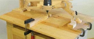
DIVISION HEAD DEVICE
The universal dividing head (Fig. 1) consists of a worm pair and a number of gears. The housing 1 is mounted on the base 2 with its axles and is secured to it with cap clamps 3 to prevent rotation. A spindle 4 rotates in the bearings of the housing, on which a winding disk 5 is attached for direct counting of the rotation of the spindle, a worm wheel 6 and a locking wheel 7.
At the front end of the spindle, next to the front disk, chucks are installed to secure the workpieces.
Rotation of the workpiece at a certain angle is carried out by rotating the handle 8 with a spring lock 9, which fixes the handle relative to the dividing disk 10. From the handle 8, rotation through the roller 11 is transmitted by gears 12 and 13. The latter is connected to a shaft 14, made integral with the falling worm 15 The worm 15 is engaged with the worm wheel 6 by rotating the eccentric 16, which lifts the worm box 17.
Rice. 1 Dividing head device
Features of the design and device of the dividing head
- • The angle when turning can be either fixed (same) or variable (different) - at the choice of the operator, for optimal positioning accuracy.
- • The workpiece is secured in the chuck. If it is too long, a tailstock should be used to ensure proper contact, but not deviate from the original base.
- • Putting this device into operation is advisable only in cases where it is more difficult or impossible to carry out any work without it.
- • It is permissible to orient the device to sequentially solve several problems - cutting grooves, cavities and teeth, boring polyhedra, and so on.
Procedure for setting up and using
How to use the dividing head on a milling machine and make transitions? This depends on the model purchased, the scale division price and other characteristics. Current standards are also important: for parts of accuracy class VIII you should be guided by the data of GOST 1.758, for IX - 1.643.
In general, preliminary debugging and preparation for operation comes down to choosing a sector based on the diameter of the circle and the required number of parts. You need to do the following:
- • convert a full cycle (360 degrees) into the required number of steps;
- • calculate the appropriate sine of the angle;
- • rotate the disk by the just found radial value;
- • fix the body with a clamp (or the handle of the unit) and place the main tool in this position.
Typically, manufacturers in their instructions indicate the formula by which the angle of the dividing head is calculated, so let’s see how to work with UDG further, let’s not dwell only on calculations, let’s move on to practice.
So, it is necessary to install the workpiece in the machine’s mandrel and, with longitudinal feed, carry out the desired operation. There is a step to consider, which depends on what kind of task is being performed. For example, when creating teeth, the discrete movement must be equal to the distance between the cavities of adjacent elements.
Productivity can be increased without compromising quality by returning the table to its original position in an accelerated manner. The most reliable way to fix it in the disk hole is with a spring.
Purpose
The dividing head allows you to transform the workpiece into the desired configuration by displacing the part relative to the axis of the machine equipment.
The UDG is fixed on the unit frame using various types of fastenings, depending on the type of attachment. The working position is adjusted using movable handles and a disk, which is equipped with holes for attaching the dividing unit.
Features of the tool in question:
- Milling of surface grooves. This process does not require perfect precision, subject to proper control of the depth and width of the workpiece being processed.
- Ability to create edges on parts. This operation is advisable when manufacturing nuts with non-standard parameters, as well as working tools and workpiece shanks. Such manipulations require high precision.
- Carrying out milling work on processing grooves and splines. In this case, significant movement of the workpiece may be required.
Types of dividing milling heads
There are 3 options that can be used to complement a wide variety of equipment - horizontally oriented, vertical, combined. Let's look at each in order.
Regular
Relevant in cases where it is necessary to divide the circle into several sectors. This problem is solved by means of a notched disk – a dial, mounted on the spindle of the equipment and having slots with holes ranging from 12 to 30 (a latch can be fixed in each of them).
Thus, within one cycle (rotation of the workpiece around its axis), it turns out to perform 2, 3, 4, 5, 6, 12, 15, 24 or even 30 equal elements, and this is in the most standard situation. And the characteristics of the UDG dividing heads, equipped with non-standard disks, even allow sections to be made unequal in size.
The rotation of the spindle is carried out by a worm mechanism: the wheel here acts as a three-phase positioning device. The position can be changed by hand by rotating the valve located on the shaft. Thanks to this, it is quite possible to increase the movement gradually (and not in jerks), which allows you to get into even a relatively small hole.
It is convenient that for the success of the operation no additional components or devices are required - only a disk operating by a direct (immediate) method is sufficient.
Multifunctional
The use of a dividing head of this type is justified in cases where the workpiece needs to be positioned at the desired angle relative to the table, and at the same time rotated around its axis. In practice, this is required, for example, when cutting screw channels.
Although in general it is used to produce the following rolled metal products:
- • flat rectangles, including large ones;
- • teeth with a cyclic arrangement;
- • polygons with equal sides;
- • parts of more complex shapes (the parameters of which can coincide with the notches on the limb).
In addition, equipment with multifunctional equipment can also provide continuous rotation of a selected part of an object (and around its own axis too) and regular turns (in accordance with a given algorithm, by certain fractions of a circle), which only expands the boundaries of operation.
Visual (optical)
This is a dividing head, the operating principle of which is aimed at ensuring high precision results for milling large parts.
It has its own marking (the rules for applying which we will discuss below), which provide information about its main parameters. It also differs in the division value on the disk, which is 15 degrees. It can be universal, then the cycle of complete rotation of the spindle is completed in 40 steps. This is suitable for those items whose maximum radius does not exceed 250 mm.
The main niche is performing precision operations, including where it is necessary to improve the results of individual equipment.
In its design, the visual (often also called visual) DG is practically no different from the design of a universal milling head. There are only three original elements:
- • glass mounted on a spindle;
- • microscope eyepiece in the upper part;
- • immobilized graduation is implemented.
Due to such solutions, the number of steps during a full cycle is increased to 60, which corresponds to formula 1. Moreover, all notches are clearly visible, so it is not a problem to set one turn in 15 seconds or another suitable mode. The rotation angle is calculated in the same way as in the case of conventional or multifunctional equipment (more on that below).
Setting up UDG: division table on the dividing head
Contains all the initial data for precise positioning
| Number of parts into which the part is divided | Full turns of the handle | Number of holes counted by sector on the disk | Number on a circle |
| 2 | 20 | – | |
| 3 | 13 | 11 | 33 |
| 4 | 13 | 10 | 30 |
| 5 | 13 | 13 | 39 |
| 6 | 10 | – | |
| 7 | 8 | – | |
| 8 | 6 | 22 | 33 |
| 9 | 6 | 20 | 30 |
| 10 | 6 | 26 | 39 |
| 11 | 5 | 35 | 49 |
| 12 | 5 | 15 | 21 |
| 13 | 5 | – | |
| 14 | 4 | 24 | 54 |
| 15 | 4/3/3 | –/21/13 | –/33/39 |
| 16 | 3 | 10 | 30 |
| 17 | 3 | 3 | 39 |
| 18 | 2 | 42 | 49 |
| 19 | 18 | 21 | |
| 20 | 22 | 33 | |
| 21 | 20 | 30 | |
| 22 | 25 | 39 | |
| 23 | 1 | 17 | 23 |
| 24 | 22 | 33 | |
| 25 | 20 | 30 | |
| 26 | 26 | 39 | |
| 27 | 18 | 30 | |
| 28 | 21 | 39 | |
| 29 | 26 | 54 | |
| 30 | 21 | 49 | |
| 31 | 9 | 21 | |
| 32 | 11 | 29 | |
| 33 | 11 | 33 | |
| 34 | 10 | 30 | |
| 35 | 13 | 39 | |
| 36 | 9 | 31 | |
| 37 | 4 | 16 | |
| 38 | 7 | 33 | |
| 39 | 3 | 17 | |
| 40 | 7 | 49 | |
| 41 | 3 | 21 | |
| 42 | 6 | 54 | |
It gives all the values for the direct method, when the workpiece is rotated without connecting any additional mechanisms.
Advantages
Working with the dividing head of a milling machine allows you to:
- • Increase the range of actions performed several times (compared to its absence).
- Ensure the most accurate and current position of the workpiece in relation to the table, both horizontal and vertical.
- • Simplify all operations related to metal objects of various sizes.
In addition, it should be noted the practical advantages characteristic of the equipment itself. So, it is quite reliable and can withstand even intensive use, and therefore is suitable for high-performance facilities. Plus, it is quite easy to learn - with a little practice, it will not be difficult to maintain, especially for an experienced craftsman. Thanks to these advantages, it pays for itself relatively quickly. In modern conditions, this is definitely an important and necessary equipment.
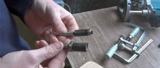
Can I do it myself?
The cost of the industrial design device in question is quite high, which is associated with the use of expensive materials and modern equipment in production. You can make a dividing head with your own hands, for which several points should be taken into account. To perform simple work, many people decide to make a turning mechanism with their own hands.
https://youtube.com/watch?v=tjVJyk-wEQg
To create the element in question, the following components are needed:
First you need a worm gearbox. Often it is taken from old technical equipment, and it can also be turned out independently. The worm gearbox is an important design element
Therefore, you need to pay attention to the quality of the design. The presence of even the slightest defects is unacceptable; you will also need a lathe chuck and a dial
The optimal diameter of the lathe chuck is 65 millimeters. They can be taken from a drawing board; In order to limit the processing progress, a locking screw is installed.
The design itself has many features that should be taken into account when making it yourself.
Disc cutters
The most convenient for cutting deep grooves of different widths are three-sided disk ones. A tool equipped with adjustable plates is more often used as a groove tool. The feature of changing the angle of the cutting elements allows you to cut a groove or groove.
Disc grooves are designed to create shallow grooves. Their teeth are located on a cylindrical body. An angle widening towards the outside helps reduce friction when cutting grooves or grooves. The peculiarity of this cutter is that it is narrower at the hub than in outer diameter.
2 and 3 sided have teeth on the end sides. Their lateral cutting edges are auxiliary, the main ones are located on the cylinder itself. Teeth located around a circle can have positive and negative angle inclination values. Negative corners at the end are cut off.
If you find an error, please select a piece of text and press Ctrl+Enter
Milling cutters are bladed metal-cutting tools, the working stroke of which represents a rotational cutting movement with a simultaneous feed movement in a direction that does not coincide with the axis of rotation. A distinctive feature of this tool is the inability to change the radius of the trajectory of the main cutting movement (GOST 25751-83).
Milling is one of the most popular methods of processing metal products. With a linear feed movement and the use of special cutting elements, cylindrical parts with a smooth surface are processed, as well as models with grooves and grooves. To carry out this kind of work, you need to buy a metal cutter that guarantees high-quality processing of various shaped elements, without reducing their strength.
Professionally manufactured cutters are distinguished by versatility and the ability to effectively process products from a wide range of materials:
- aluminum;
- various types of steel;
- alloys that differ in the percentage of non-ferrous and ferrous metals;
- copper, etc.
Each of the listed materials is characterized by an individual level of hardness, density, etc. To take these characteristics into account, a variety of metal cutters are available on the specialized market. They differ in their type of design, size, frequency and direction of teeth, type of installation and a number of other characteristics.
Metal cutters are characterized by maximum blade strength and a precisely set, constant trajectory of movement. The feed is carried out in a direction other than axial rotation. These features of the cutting surface fully comply with the requirements of GOST 25751-83.