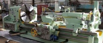
16K20F3 is a chuck-center lathe, its main purpose is turning parts such as rotating bodies in a closed semi-automatic cycle. The 16K20F3 lathe was made on the basis of the 16K20 screw-cutting lathe. It is also designed for processing parts with a curved or stepped profile in the axial section.
Lathe 16A20F3
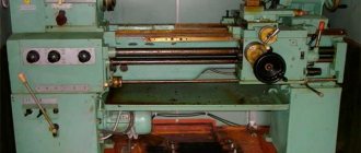
The 16A20F machine is designed for turning external (diameter up to 400 mm) and internal surfaces of parts (length up to 1000 mm) with a stepped and curved profile in the axial section in a closed semi-automatic cycle.
The 16A20F3 lathe is designed on the basis of the 16K20F3 screw-cutting lathe, so the layout, components and movements of these machines are the same. The design of the machines has been largely unified.
The CNC device of the machine (the machine can be equipped with various types of CNC systems: open, closed, CNC) provides shaping movement (the number of simultaneously controlled coordinates is two), changing feed values, switching spindle speeds, indexing the cutting head and threading according to the program.
Machine tools can be produced with various CNC devices, designed for integration into flexible production modules (GPM), as well as in special and specialized versions when equipped with adjustments in agreement with the customer.
16A20F3 machines can be equipped with removable tool heads with 6, 8 and 12 position tool holders with a horizontal axis of rotation.
Design Features:
- high-strength bed
made of cast iron grade SCh20 with heat-treated ground guides ensure long service life and increased processing accuracy - main motion drive
including 11 kW main motor and spindle head provides the highest torque of up to 800 Nm - high-precision spindle
with a bore of 55 mm (optional 64 mm), allowing the processing of parts made of bar material; the processing zone can be equipped with both a linear adjustment and a turret - reliable protection of ball screw pairs
ensures durability of the movement mechanisms along the X and Z coordinates; the machine is equipped with CNC systems and electric drives, both domestically produced and manufactured by foreign companies
Main movement mechanism of the machine
The machine is equipped with a 16A20F3.025 spindle head. having three ranges with a ratio of 1.25:1; 1:2; 1:5.8; manually switchable.
The machine spindle is mounted in double-row and single-row conical bearings. Bearings are adjusted at the machine manufacturer's factory and do not require adjustment during operation.
The position of the spindle head axis on the frame is adjusted using two screws. The spindle head is lubricated from a lubrication station mounted on the base of the machine. To ensure the possibility of threading, a threading sensor is installed on the spindle head.
A frequency-controlled asynchronous electric motor with a control range with a constant power of 1500...4500 rpm (1000...3500 with DC motors made in Bulgaria) is used as the main movement drive.
The transmission of rotation from the electric motor to the first shaft of the spindle head is carried out by a 2240L20 poly V-belt with a gear ratio of 115:257 (160:257 in the case of using a DC electric motor manufactured by NRB).
The base of the machine is a rigid casting. The base, the electric motor of the main movement, lubrication stations for the guides of the carriage and the spindle head are installed on the base. Two types of bases are used:
- with a window for chip collection and an opening for installing a chip removal conveyor, which is inserted from the right side;
- without a window, divided vertically in the middle part by a solid partition, in this case the middle part of the base serves as a collector for chips and coolant, the compartment in the lower right part of the base serves as a coolant reservoir, and a coolant pump is installed at the rear on the right side of the base.
| The largest diameter of the product installed above the frame, mm | 500 |
| The largest diameter of the workpiece above the bed, mm | 320 |
| The largest diameter of the workpiece above the support, mm | 200 |
| Maximum length of the installed product in centers, mm | 900 |
| Diameter of cylindrical hole in spindle, mm | 55 |
| Maximum transverse travel of the caliper, mm | 210 |
| Maximum longitudinal stroke of the caliper, mm | 905 |
| Number of controlled coordinates | 2 |
| Number of simultaneously controlled coordinates | 2 |
| Spindle speed range, min-1 | 20…2500 |
| Maximum speed of fast movements - longitudinal, mm/min - transverse, mm/min | 7500 4000 |
| Number of tool head positions | 8 |
| Main drive drive power, kW | 11 |
| Total power consumption, kW | 13 |
| Overall dimensions of the machine, mm | 3700x2260x1650 |
| Machine weight, kg | 4050 |
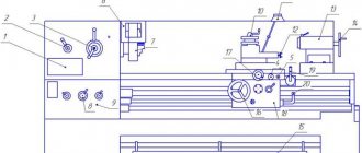
What does it consist of?
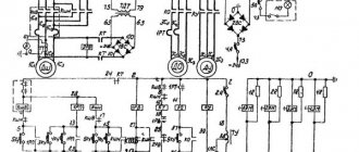
The technical characteristics of 16K20F3 are determined by the design and kinematic diagram of the machine. The unit is made in a traditional layout that meets universal standards and also allows for a wide range of operations.
Equipment components:
- Frame (frame).
- Frame.
- Caliper carriage.
- Rotary type tool holder.
- Tailstock and spindle headstock.
- Automatic transfer box.
- Guide elements.
- Electromagnetic couplings.
- Transverse and longitudinal drives.
- Hydraulic booster.
Features of design and functionality
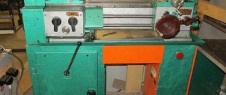
Appearance
This machine is designed for various types of turning of workpieces. The diameter limit is 40 cm for external turning. When internal turning, the length of the workpiece should not exceed 100 cm.
The main advantage is the ability to install various types of CNC – closed, open and STS. For this purpose, the design provides contact connectors. The number of controlled coordinates when performing shaping is limited to two.
Additionally, the presence of automatic control allows you to perform the following operations on the 16K20F3 lathe, specified in the passport:
- automatic control over the feed value;
- changing the number of spindle revolutions;
- the ability to form threads according to the drawn up program.
To these qualities it is worth adding high precision of the work performed and good performance characteristics. According to the GOST 8-82 classification, the 16K20F3 machine has an accuracy rating of “P”. To adapt to the specific type of operations performed, turning equipment of this type can be equipped with additional modules and an expanded range of settings.
This is interesting: Turret lathes - design, operating principle
Technical characteristics, description and passport 16K20
16K20 Screw-cutting lathe is a universal equipment for precise processing of metal products in full compliance with international quality standards. The objective advantages of machines of this type include convenient operation, wide functionality and excellent performance indicators, which guarantee high results and maximum efficiency when used correctly in repair, production and other metalworking enterprises. As a rule, screw-cutting lathes are used to perform technological operations of varying complexity with the external and internal surfaces of parts, including rotating bodies that have a varied axis profile. In addition, the 16K20 lathe is very often used for quick and convenient cutting of left-hand and right-hand threads (metric, inch, modular and pitch), fully meeting the needs of enterprises in all sectors of modern industry. The screw-cutting lathe 16K20 has an expanded package that includes all the necessary equipment to ensure successful operation:
- gearbox
- electrical cabinet
- feed box
- headstock
- chuck guard
- bed
- carriage and support
- apron
- caliper guard
- tailstock
Technical characteristics of the lathe 16K20
| Accuracy class according to GOST 8-82 | N |
| The largest diameter of the workpiece installed above the bed, mm | 400 |
| Height of the center axis above the flat guides of the frame, mm | 215 |
| The largest diameter of the workpiece processed above the support, mm | 220 |
| Maximum length of the part installed in the centers (RMC), mm | 710, 1000, 1400, 2000 |
| The greatest distance from the axis of the centers to the edge of the tool holder, mm | 225 |
| The largest diameter of the drill when drilling steel parts, mm | 25 |
| The largest mass of the part processed in the centers, kg | 460..1300 |
| Maximum mass of the part processed in the chuck, kg | 200 |
| Spindle | |
| Spindle hole diameter, mm | 52 |
| The largest diameter of the rod passing through the hole in the spindle, mm | 50 |
| Spindle rotation speed in forward direction, rpm | 12,5..1600 |
| Spindle rotation speed in reverse direction, rpm | 19..1900 |
| Number of forward spindle speeds | 22 |
| Number of spindle reverse speeds | 11 |
| Spindle end according to GOST 12593-72 | 6K |
| Tapered spindle bore according to GOST 2847-67 | Morse 6 |
| Spindle flange diameter, mm | 170 |
| Maximum torque on the spindle, Nm | 1000 |
| Caliper. Submissions | |
| Maximum length of longitudinal movement, mm | 645, 935, 1335, 1935 |
| Maximum length of transverse movement, mm | 300 |
| Speed of fast longitudinal movements, mm/min | 3800 |
| Speed of fast transverse movements, mm/min | 1900 |
| Maximum permissible speed of movement when working on stops, mm/min | 250 |
| Minimum permissible speed of movement of the carriage (support), mm/min | 10 |
| Price for dividing the longitudinal movement dial, mm | 1 |
| Transverse movement dial division price, mm | 0,05 |
| Longitudinal feed range, mm/rev | 0,05..2,8 |
| Transverse feed range, mm/rev | 0,025..1,4 |
| Number of longitudinal feeds | 42 |
| Number of cross feeds | 42 |
| Number of threads to be cut - metric | |
| Number of threads to be cut – modular | |
| Number of threads cut - inch | |
| Number of threads to be cut - pitch | |
| Limits of metric thread pitches, mm | 0,5..112 |
| Limits of pitches of inch threads, threads/inch | 56..0,5 |
| Limits of modular thread pitches, module | 0,5..112 |
| Limits of pitch thread pitches, diametric pitch | 56..0,5 |
| The greatest force allowed by the feed mechanism on the cutter is longitudinal, N | 5884 |
| The greatest force allowed by the feed mechanism on the cutter is transverse, N | 3530 |
| Cutting slide | |
| Maximum length of movement of the cutting slide, mm | 150 |
| Movement of the cutting slide by one division of the dial, mm | 0,05 |
| Scale of rotation angle of the cutting slide, deg | ±90° |
| Scale division of the tool slide rotation scale, deg | 1° |
| The largest cross-section of the cutter holder, mm | 25 x 25 |
| Height from the supporting surface of the cutter to the axis of the centers (cutter height), mm | 25 |
| Number of cutters in the cutting head | 4 |
| Tailstock | |
| Quill diameter, mm | |
| Tailstock quill hole cone according to GOST 2847-67 | Morse 5 |
| Maximum movement of the quill, mm | 150 |
| Movement of the quill by one division of the dial, mm | 0,1 |
| The amount of lateral displacement of the headstock body, mm | ±15 |
| Electrical equipment | |
| Main drive electric motor, kW | 11 |
| Electric motor for fast movement drive, kW | 0,12 |
| Coolant pump electric motor, kW | 0,125 |
| Dimensions and weight of the machine | |
| Machine dimensions (length width height) RMC=1000, mm | 2795 x 1190 x 1500 |
| Machine weight, kg | 3010 |
Series TS16k20f3 (Russia)
- Review
- The lineup
- Photo gallery
- Documentation
When choosing a CNC lathe, it is recommended to pay attention to the following factors: main characteristics - possible range of processing diameters and processing lengths of workpieces.
A small machine will not process large workpieces, a large machine takes up a lot of space and consumes more electricity - the number of toolholder positions, the type of mandrel and the cross-section of the cutter. Auxiliary characteristics all other characteristics of the machine
- the diameter of the chuck, the presence of a passage hole in it and the diameter of the hole. The diameter of the hole determines the maximum size of the bar workpiece that can fit in the spindle - the power of the spindle, the torque on the spindle, the spindle speed range and the torque on the ball screw of the feed axes - determine the technological modes (and possibilities) material removal. The design of the machine is a one-piece cast frame with horizontal sliding guides, on which a headstock with a main spindle, a support with a turret and a tailstock are installed. The spindle has a main movement in forward and reverse directions. The support with the turret head moves in the longitudinal and transverse directions.
stankomach.com
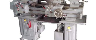
Machine design
The basis of the device is a durable U-shaped frame with 2 hardened, ground guides on top. It is installed on pedestals in a cast metal support, which is used as a trough for emulsion and collecting chips. The main electric drive is located in the cabinet on the headstock side of the product.
Dimensions of screw-cutting lathe 16K20
Machine dimensions: length 2505, 2795, 3195 or 3795 mm; width 1190 mm; height 1500 mm. The weight of the machine depends on its length and can be 2.835; 3.005; 3.225 or 3.685 per 103 kg.
Spindle
The spindle shaft is steel with a through longitudinal hole through which a rod is passed, used as a workpiece, or a drift when knocking out the front center. To rotate the spindle in this machine, specialized precision rolling bearings are used. They are distinguished by high manufacturing precision and wear resistance, so they do not require periodic adjustments during maintenance during the operational period.
The shaft supports are lubricated by oil supplied to them under pump pressure. The front end of the spindle shaft is made in accordance with GOST 12593 - with a short centering cone 1:4.
Headstock
The headstock or headstock of the workpiece serves to fix one end of the workpiece and transmit torque to it. It houses the spindle, bulkhead box and other components. On the outside there are switching levers for the bulkhead box.
The output shaft of the headstock of the product is connected through gears to the feed reducer. The latter allows the slide to carry out the feed movement using the drive shaft during turning. Or by means of a lead screw for thread cutting. Which can be connected to the feed box without intermediate links.
Apron
This unit is necessary to move the caliper with the tool holder both along and across the axis of rotation of the part. It converts the rotary motion of the screw into linear displacement of the caliper. You can move the latter not only manually, but also by taking away part of the rotational torque from the spindle. The apron of this machine is equipped with a high-precision feed cut-off device on a stop, a design that has not been seen before.
Caliper
Designed to hold the tool holder with the cutter fixed in it near the workpiece. Possessing several degrees of freedom, it can move under the influence of the apron to form the desired surface character of the part with a cutter. To control the amount of movement, the unit is equipped with scale rulers with sighting devices that increase the accuracy and ease of reading readings.
Tailstock
She's a stubborn grandma. It is installed on guides that allow it to move along the machine. It has a tapered hole coaxial with the headstock output shaft. Which allows you to set a center to support the second end of the blank. Or a reamer, tap, drill and other similar ones for performing operations from the open end of the workpiece.
Headstock of lathe 16k20
The headstock contains the gearbox and spindle assembly. The spindle transmits torque to the workpiece through devices. For installation and centering of devices, a flange is used, a conical neck is used for installing cartridges, and a conical hole is used for installing centers. In lathes, this hole is made using a Morse taper. The front ends of the spindles are standardized (for lathes with flanged front ends of the spindles GOST 12593-81).
The guitar is used to adjust the feed chain using the selection of replaceable gears for cutting metric, inch, modular, pitch threads, as well as for adjusting the pitch (stroke) of the thread when cutting non-standard threads. In double-pair guitars, the distance L between the shaft I; shaft II is constant. A slope is freely mounted on shaft II, which is attached to the wall of the spindle head using a bolt.
Lathe apron 16k20
An apron is a mechanism for converting the rotation of a lead screw or lead shaft into translational movement of a caliper. The caliper receives translational movement from the lead screw through a split nut, and from the drive shaft through a series of gears through a rack and pinion gear.
This is interesting: TV-6 lathe - device, technical characteristics
Principle of operation
The 16K20F3 machine, the technical characteristics of which allow you to select up to 9 shaft rotation speeds, operates as follows:
- The metal part is mounted in a spindle driven by a V-belt drive from an electric motor.
- The processing speed is adjusted using an automatic transmission and spindle assembly.
- The automatic transmission is equipped with six electromagnetic clutches, the combined activation of which allows you to select the required speed.
- To increase or decrease speed, spindle head gears are used. They are manually controlled and adjust up to 12 positions.
- The installation carriage is adapted for longitudinal movement using an electromagnetic drive.
- The transverse movement of the caliper and tool holder is carried out through the drive, gear wheel and lead screw.
- The rotary tool holder can be mounted in six positions with changing processing angles and the horizontal axis of rotation of the plane. In addition, the fastening of the transverse caliper is involved in these manipulations.
- A tool head is positioned on the tool holder, designed to use no more than six cutters processing the workpiece according to a given program.
Technical characteristics of the machine 16B20
| Parameter name | 16В20 | 1V62G | 1V625M |
| Main settings | |||
| Accuracy class according to GOST 8-82 | N | N | N |
| The largest diameter of the workpiece above the bed, mm | 445 | 445 | 500 |
| The largest diameter of the workpiece above the support, mm | 220 | 220 | 290 |
| The largest diameter of the workpiece above the frame recess, mm | – | 620 | 690 |
| Maximum workpiece length (RMC), mm | 750,1000,1500 | 750,1000,1500 | 1000,1500,2000 |
| Maximum turning length, mm | 650,900,1400 | 650,900,1400 | 900,1400,1900 |
| Maximum mass of the workpiece in the chuck, kg | |||
| The largest mass of the workpiece in the centers, kg | |||
| Spindle | |||
| Diameter of through hole in spindle, mm | 54 | 54 | 60 |
| Maximum rod diameter, mm | |||
| Number of speed steps for direct spindle rotation | 24 | 24 | 24 |
| Spindle direct rotation frequency, rpm | 10…1400 | 10…1400 | 10…1400 |
| Number of spindle reverse rotation frequency steps | 12 | 12 | 12 |
| Spindle reverse rotation frequency, rpm | |||
| Size of the inner cone in the spindle | M5 | M5 | M5 |
| Spindle end according to GOST 12593-72 | 6K | 6K | 6K |
| Submissions | |||
| Maximum longitudinal movement of the caliper carriage, mm | 900 | 900 | 900 |
| Maximum lateral movement of the caliper, mm | 280 | 280 | 302 |
| Maximum lateral movement of the upper support (slide), mm | 130 | 130 | 130 |
| Number of longitudinal/transverse feed stages | 50/ 50 | 50/ 50 | 50/ 50 |
| Limits of longitudinal feed speed, mm/rev | 0,018..22,4 | 0,018..22,4 | 0,036..22,4 |
| Transverse feed speed limits, mm/rev | 0,009..11,2 | 0,009..11,2 | 0,018..11,2 |
| Speed of fast movements of the caliper, longitudinal/transverse, m/min | 4/ 2 | 4/ 2 | 4/ 2 |
| Longitudinal movement per dial division, mm | 1 | 1 | 1 |
| Longitudinal movement per vernier division, mm | 0,1 | 0,1 | 0,1 |
| Transverse movement of the caliper per dial division, mm | 0,05 | 0,05 | 0,05 |
| Movement of the slide by one division of the dial, mm | 0,05 | 0,05 | 0,05 |
| Number of metric threads to be cut | 36 | 36 | 36 |
| Limits of pitches of cut metric threads, mm | 0,5..224 | 0,5..224 | 0,5..224 |
| Number of inch threads to be cut | 45 | 45 | 45 |
| Limits of pitches of cut inch threads | 77..0,125 | 77..0,125 | 77..0,125 |
| Number of modular threads to be cut | 36 | 36 | 36 |
| Limits of pitches of cut modular threads | 0,5..224 | 0,5..224 | 0,5..224 |
| Number of cut pitch threads | 45 | 45 | 45 |
| Limits of pitches of cut pitch threads | 77..0,125 | 77..0,125 | 77..0,125 |
| Overload fuse | There is | There is | There is |
| Blocking longitudinal and transverse feeds | There is | There is | There is |
| Switching longitudinal stops | There is | There is | There is |
| Surface roughness of a workpiece made of structural steel during finishing turning, microns, no more | Ra 2.0 | Ra 2.0 | |
| Tailstock | |||
| Maximum length of movement of the tailstock quill, mm | 150 | 150 | 150 |
| Maximum movement of the tailstock, mm | ±15 | ±15 | ±15 |
| Electrical equipment | |||
| Number of electric motors on the machine | 3 | 3 | 3 |
| Main drive electric motor, kW | 7,5 | 7,5 | 7,5 |
| Accelerated motion drive, kW | 0,75 | 0,75 | 0,37 |
| Cooling pump electric motor, kW | 0,12 | 0,12 | 0,12 |
| Total power, kW | 8,37 | 8,37 | |
| Dimensions and weight of the machine | |||
| Machine dimensions (length width height) (RMC 1000), mm | 2800 1190 1450 | 2800 1190 1450 | 2800 1370 1700 |
| Machine weight (RMC 1000), kg | 2450 | 2430 | 2430 |
Bibliography:
Screw-cutting lathes 16V20, 16V20A, 1V62G, 1V62GA, 1V625. Operating manual, 2004 Screw-cutting lathes 16V20, 1V62G, 1V625M. Operating manual 16В20.00.000 РЭ Screw-cutting lathes 16В20, 1В62Г. Operating manual 1V62G.00.000 RE3, 1993
Acherkan N.S. Metal-cutting machines, Volume 1, 1965
Batov V.P. Lathes., 1978
Beletsky D.G. Handbook of a universal turner, 1987
Denezhny P.M., Stiskin G.M., Thor I.E. Turning, 1972. (1k62)
Denezhny P.M., Stiskin G.M., Thor I.E. Turning, 1979. (16k20)
Modzelevsky A. A., Muschinkin A. A., Kedrov S. S., Sobol A. M., Zavgorodniy Yu. P., Lathes, 1973
Pikus M.Yu. A mechanic's guide to machine repair, 1987
Skhirtladze A.G., Novikov V.Yu. Technological equipment for machine-building industries, 1980
Tepinkichiev V.K. Metal cutting machines, 1973
Chernov N.N. Metal cutting machines, 1988
Related Links. Additional Information
Home About the company News Articles Price list Contacts Reference information Download passport Interesting video KPO woodworking machines Manufacturers
CNC system
The 16K20F3 lathe is equipped with various CNC systems. Machine modifications, depending on the configuration of the CNC device, have different indices (for example, 16K20F3S32). The contour CNC system ensures the movement of shaping, changing the feed rates and spindle speeds in the processing cycle, indexing the rotary tool holder, and cutting threads according to the program. The number of simultaneously controlled coordinates is 2, the total controlled coordinates are 2. The discreteness of specifying transverse feed movements (along the X axis) is 0.005 mm, longitudinal movements (along the Z axis) is 0.01 mm. The 16K20F3 machine with a 2P22 CNC device is equipped with a KEMRON main drive and a KEMTOK feed drive along the Z and X axis.
The alphanumeric index of the machine 16K20F3 means the following: number 1 is a lathe; number 6 - designates a screw-cutting lathe, letter K - generation of the machine, number 20 - height of the centers (200 mm). The presence of “F3” at the end of the index indicates the presence of CNC - numerical program control.
| Specifications | Options |
| Machining diameter above the bed, mm | 500 |
| Machining diameter above the support, mm | 200 |
| Maximum processing length, 6-position head, mm | 900 |
| Maximum processing length, 8-position head, mm | 750 |
| Maximum processing length, 12-position head, mm | 850 |
| Maximum processing length in centers, mm | 1000 |
| Diameter of cylindrical hole in spindle, mm | 55 |
| Maximum lateral stroke of the caliper, mm | 210 |
| Maximum longitudinal stroke of the caliper, mm | 905 |
| Maximum recommended speed of longitudinal working feed, mm | 2000 |
| Maximum recommended speed of transverse working feed, mm | 1000 |
| Number of controlled coordinates, pcs. | 2 |
| Number of simultaneously controlled coordinates, pcs. | 2 |
| Discreteness of movement task, mm | 0,001 |
| Spindle speed limits, min-1 | 20 — 2500 |
| Speed of fast movements of the caliper - transverse, mm/min | 2 400 |
| Maximum speed of fast longitudinal movements, mm/min | 15000 |
| Maximum speed of fast transverse movements, mm/min | 7500 |
| Number of tool head positions | 8 |
| Power of the electric motor of the main movement, kW | 11 |
| Accuracy class according to GOST 8-82 | P |
| Overall dimensions of the machine (L x W x H), mm | 3700 × 2260 × 1650 |
| Machine weight, kg | 4000 |
The high-strength machine bed 16K20F3 is made of cast iron SCh20 with heat-treated ground guides, ensuring long service life and increased processing accuracy. The main movement drive, which includes a 11 kW main motor and a spindle head, provides the highest torque of up to 800 Nm. High-precision spindle with a 55 mm bore (64 mm on request), allowing the processing of parts made of bar material. The processing area can be equipped with either a linear adjustment or a turret, depending on the customer's requirements. Reliable protection of ball screw pairs ensures the durability of the movement mechanisms along the X and Z coordinates. The 16K20F3 machine is equipped with CNC systems and electric drives, both domestically produced and manufactured by foreign companies. Feedback and threading sensors model VTM-1M.
The tool movement program, main drive control and auxiliary commands are entered into the control system memory from the operator console keyboard, as well as from an external memory cassette and can be adjusted from the CNC operator console with visualization on the digital display panel.
Automatic tool head
The 16K20F3 CNC lathe is equipped with a 6-, 8- or 12-position automatic universal head (UG9321, UG9324, UG9325) with a horizontal rotation axis. The head has a tool disk for 6 radial and 3 axial tools (6-position) or 8 blocks for radial and axial tools (8-position) or 12 blocks for radial and axial tools, combined when setting up a part (12-position).
Full set price
Today, many businesses are selling off their equipment to install modern and innovative production lines. A fully equipped CNC lathe 16K20F3 can be purchased for a price starting from 300 thousand rubles. The market offers different prices, the average size is 500 thousand rubles. If you buy modernized models, then the cost will be from 800 - 1 million rubles.
To this day, the 16K20F3 CNC lathe is considered one of the most successful equipment models, on the basis of which domestic and foreign engineers have developed and are creating analogues that successfully operate in large and small-scale production of a variety of products with excellent quality characteristics.
In addition to the machine itself, you can buy various components and spare parts: the model is considered universal and many elements produced for other series of turning equipment are suitable for it.