Moskovsky was the first to produce such machines. Since 1950, the manufacturer of DIP-500 has been the Ryazan Machine Tool Plant.
The machine is used for all types of turning and processing of workpieces made of materials such as steel, cast iron, wood, composite, fluoroplastic. You can do the following operations on it:
- thread cutting;
- trimming ends;
- manufacture long and short cones;
- high speed cutting work;
- processing of pipes with a diameter of up to 100 mm;
- boring holes.
In the marking of the screw-cutting lathe DIP-500: DIP means the above slogan, and 500 is the value of the height of the centers above the bed - 500 millimeters.
Download the passport of the lathe 1M65 (DIP-500)
In the marking of ENIMS (Experimental Research Institute of Metal-Cutting Machine Tools), model 1M65 stands for:
1 is the designation of the group number of lathes;
M is a designation for the modernization of the base model;
6 is the designation of the machine type;
5 is a designation of the main characteristic of the machine model - the height of the centers above the bed is 500 millimeters.
Purpose and scope of application
The machine is used for all types of turning and processing of workpieces made of materials such as steel, cast iron, wood, composite, fluoroplastic. You can do the following operations on it:
- thread cutting;
- trimming ends;
- manufacture long and short cones;
- high speed cutting work;
- processing of pipes with a diameter of up to 100 mm;
- boring holes.
Important!
The machine has been in use for decades and is still widely used in enterprises. Using additional devices, special operations can be performed on it. It is possible to produce both piece parts and serial products.
Order a screw-cutting lathe 1m65, 165, (deep 500)
We supply refurbished metalworking machines. We have all the capabilities to carry out major repairs of metal-working machines, including: Screw-cutting lathe 1M65 The machine is designed to perform a variety of turning operations, including turning cones and cutting threads: metric, inch, modular. The technical characteristics and rigidity of the machine make it possible to fully utilize the capabilities of high-speed and carbide tools when processing ferrous and non-ferrous metals. Technical characteristics of the machine 1M65 Parameters Largest machining diameter above the bed, mm 1,000 Machining diameter above the support, mm 650 Distance between centers 3,000 – 10,000 Headstock spindle end size according to DIN 2-15M Diameter of a cylindrical hole in the spindle, mm 128 Number of frequency steps spindle rotation 24 Spindle rotation speed limits, rpm 5 – 500 Accelerated longitudinal movement of the support, m/min 3 Accelerated transverse movement of the support, m/min 1 Electric motor power of the main drive 22 kW Maximum weight of the workpiece in the centers, kg 8,000 (10 000) Overall dimensions of the machine (L x W x H), mm 6,140 – … x 2,200 x 1,770 Weight of the machine, kg 12,800 – …
Screw-cutting lathe (1N65, 1M65, 165, DIP500) RMC 5000mm.
Screw-cutting lathe (1N65, 1M65, 165, DIP500) RMC 5000mm. designed for performing a variety of turning operations, including turning cones and cutting threads: metric, inch, modular, pitch. High drive power and rigidity with…
Screw-cutting lathe 1N65 (1M65) is designed to perform
The screw-cutting lathe 1N65 (1M65) is designed to perform a variety of turning operations, including turning cones and cutting threads: metric, inch, modular, pitch. High drive power and machine rigidity, wide h...
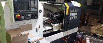
Screw-cutting lathe STALEX CM6241/1500
• Automatic longitudinal and transverse feed • Siemens electrical components • Massive frame design made of high-quality cast iron, as well as ground guides, guarantee vibration-free operation. • Automatic feed along two axes X/Y. • Installed…
Screw-cutting lathe STALEX CM6241/1000
• Automatic longitudinal and transverse feed • Siemens electrical components • Massive frame design made of high-quality cast iron, as well as ground guides, guarantee vibration-free operation. • Automatic feed along two axes X/Y. • Installed…
Technical characteristics and operating principle
Lathe Features:
- normal accuracy of turning parts;
- the presence of additional supports allows you to sharpen long parts;
- the largest size of the workpiece is 100 cm, above the support – 60 cm;
- maximum workpiece weight – 5000 kg;
- the equipment operates using 4 electric motors of different power;
- cooling and lubrication are carried out using two pumps;
- the caliper can move both along and across in accelerated mode;
- Changing gears allows you to precisely adjust the size of thread pitches.
The main working moment is cutting the part while it is rotating in the chuck or centers. The cutting tool can be moved using the auxiliary feed motion.
Cross feed regulates the processing depth. The cutter configuration determines the shape of the part.
Related Posts via Categories
- Characteristics of 1K62 - features of the machine in numbers
- 1M63 - a solid tool for a turner and carving master
- School lathe - why is it popular not only in labor lessons?
- Mini lathe - indispensable equipment for miniature machining
- DIP-500 – screw-cutting lathe for single jobs
- JET BD-7 lathe – desktop unit for home use
- Accessories for a lathe - how to make the unit more functional?
- IZH-250 - the legendary lathe of Izhmash
- Corvette 403 – a functional lathe for amateurs and professionals
- TRENS SE 320 and other machines from a famous European manufacturer
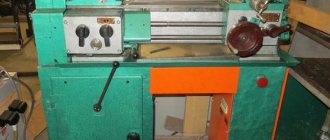
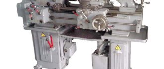
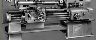
Design features of the machine
The DIP-500 machine has a conventional design for machines of its class. It is resistant to vibrations and heavy loads. The parts are made of cast iron.
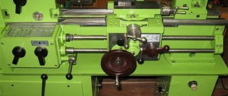
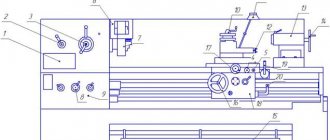
Location of controls
On the front panel there are controls - five handles, above which there is a special plate describing the positions of the handles and their modes.
They control turning the engine on and off, setting the thread pitch and direction, and regulating the rotation speed.
Headstock
It is used to secure the part, give it rotation, and with its help all processing parameters are regulated. The headstock is located to the left of the turner.
Caliper
The caliper moves along the frame between the headstocks and feeds the cutter to the part, determining the speed and pitch of the thread. It can operate in two modes: manual and mechanical.
Apron
Used to move the carriage. Can work both mechanically and manually. There is another trigger mechanism on the apron, which can also turn on the machine and change the rotation of the part.
The front apron cover is removed, inside it there is an overrunning clutch.
Gearbox
The box is located on the headstock and is responsible for controlling the transmission mechanism. With its help, you can turn on the motion shafts and set thread parameters. It provides cutting of metric, inch and modular threads.
Replacement gears
The replacement gears are located in an assembly called the "guitar". They transmit rotation to the feed box.
Tailstock
Located to the right of the worker. Can be moved around the frame by rotating the handle and gearbox. Tools for carving, making holes are attached to it, and parts are precisely fixed.
History of the model
He was the first in the USSR to begin producing universal screw-cutting lathes in the thirties of the twentieth century. In its markings of machine tools, the plant had the slogan of the USSR machine tool industry - DIP. This abbreviation stands for “catch up and overtake.” Subsequently, DIP-500 began to be produced by the Ryazan Machine Tool Plant in the fifties of the twentieth century, and it received the marking 1M65.
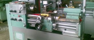
Headstock
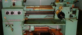
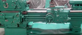
Side view
Tailstock and bed
Operating instructions, passport
For proper operation of the machine, you must follow the operating instructions.
- The machine weighs more than 10 tons; together with the workpiece, its weight can increase significantly. Therefore, it is necessary to prepare a separate foundation and a flat, stable platform.
- The device has four electric motors. For them to work, you need to correctly calculate the electrical load. The equipment operates from a three-phase 380 V network.
- During installation, it is necessary to check the reliability of all fasteners. Be sure to monitor the oil level and timely lubrication of mechanisms.
- The bed must be installed strictly horizontally both lengthwise and crosswise. Check the level.
The passport of the DIP-500 machine is similar to its new model 1M65. It can be viewed here.
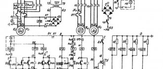
Electrical circuit diagram of the screw-cutting lathe DIP-500
Electrical diagram of the DIP-500 lathe
Electric motors of the screw-cutting lathe DIP-500
The machine is equipped with a three-phase electric motor of normal design with a squirrel-cage rotor. Electric motor type MA202-2/4 with a power of 17 kW, 1500 rpm. Power factor - cosφ = 0.875; the rated current when connecting its windings with a star and when connected to a 380 V network will be 33.3 A, and when connecting the windings with a triangle and connecting to a 220 V network it will be 57.5 A. The electric motor is installed on a skid and connected to the machine by a belt drive .
The coolant is supplied by an electric pump of the ENTS-3 type, mounted on a bracket on the rear side of the machine support carriage. An electric pump consists of an electric motor and a pump mounted on one common shaft. Electric motor with a power of 0.37 kW 2800 rpm, power factor - cosφ = 0.74 kW, efficiency = 0.82, voltage 220/380 V, current 1.9/1.1 A.
Electrical equipment of the screw-cutting lathe DIP-500
1) Magnetic starter. The main motor is controlled by a reversible magnetic starter of the PM-52 type, consisting of two contactors from 3 main contacts and one normally open contact block. The contactors are driven by electromagnets on which a coil is installed for a voltage of 220 or 380 V, depending on the network voltage.
The contactors have a mechanical interlock. To protect the electric motor from overloads, the magnetic starter contains a maximum thermal relay installed on two phases. These relays are equipped with heating elements of type NE105/45 at 220 V and type NE105/38 at 380 V mains voltage.
A thermal relay cannot protect an electric motor from short circuits, since it does not act instantly, but with a certain time delay, which is inversely related to the magnitude of the overload. The electric motor must be protected from short circuits by fuses installed outside the machine by the customer.
2) Push-button stations. Turning on, off and reversing the main engine is done by pressing the corresponding “Forward”, “Stop” or “Back” buttons on the push-button stations.
Two push-button stations of the KU-430 type are installed on the machine. One of them is located at the headstock, and the second is installed on the carriage.
3) Three-pole switches. To control the electric pump, a three-pole packet switch of the PKZ-6/500 type is installed on the apron of the machine carriage in the same box with the push-button station.
The batch switch can be replaced by a three-pole switch of the EL-1 type.
4) Fuses. To protect the electric pump from short circuit currents, type H fuses with normal Edison threads are placed in the same box in which the push-button station and package switch are installed.
5) Wiring on the machine is carried out in gas pipes, as well as in flexible metal hoses. To supply wires, a flexible connection is arranged in the carriage in the form of a bundle of wires stretched into a flexible rubber tube and suspended in a spiral on two steel cables at the back of the machine; Thus, when the carriage moves while working along the machine bed, the spiral either stretches or contracts, providing an unbreakable connection in the electrical circuit.