Coming to a cop and finding problems with the metal detector is sad... You stand in the middle of a field, waving the detector like a fool, listening to wild songs. When traveling by car over 100 km, I keep at least 2 detectors in the trunk. If you are a travel companion, you always have a second coil in your backpack. My spare coil has already helped the comrades continue their digging several times.
Let's look at a step-by-step list of what to do if the metal detector coil is faulty.
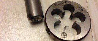
An example of how this happens (not mine):
What is a metal detector and how does it work?
A modern electronic device detects the presence of metal objects at a distance. The principle of operation is based on the fact that it picks up its own radio wave reflected from the metal.
When the power is turned on, an electromagnetic field appears in the search device, which is emitted deep into the area under study. It can be earth, rock, water, wood or an array of any dielectric. The electromagnetic field is emitted by the search coil.
Eddy currents appear on the upper part of the desired metal. They rush towards you, suppressing the electromagnetic field emitted by the metal detector. A sharp drop in the field power of the device is recorded by its electronic unit. Electronics analyzes new parameters of the electromagnetic flux and signals the presence of metal.
Gold, silver and copper, unlike iron and nickel, have higher electrical conductivity. Determining the nature of the metal in the survey area is based on obtaining data on the electrical conductivity of the material.
The difference between simple designs and devices with more sophisticated electronics is that expensive devices are determined not only by the type of metal, but also by the depth of its location, and also have a discrimination option.
Coil problems
Problems The metal detector coil is conventionally divided into 4 zones: connector, cable, cable outlet from the coil, and the coil itself.
Sometimes the problem is on the surface and easy to detect. You pull the connector, bend the cable, move the cable lead out of the reel. But there are worse cases...
Sudden loss of depth . The coil sees targets only at point blank range. For example, a nickel E2 up to 5 centimeters. One circuit is torn off. Look where (connector, cable, output from the coil).
The coil does not see silver or large copper. The coil is not tuned (defective). Please note this may be the case on certain settings. For example, frequency shift when detuning from interference.
Phantoms when shaken in the air. There may be either a cable or loss of circuit attachment points inside. In this case, I would try to tap the coil, while trying to keep the wire still. If there is a wire, the repair is easier. If the circuit is not fastened inside (for example, it breaks off from a side impact, or softens in the heat), you cannot do without opening the filling.
Operating principles of metal detectors
The composition of the device circuits directly depends on the operating principle of the metal detector electronics. The following types of schemes are distinguished:
- beating method;
- transmitter-receiver;
- radio frequency;
- pulse-induction;
- resonant-stalling.
Beating method
This method of action is abbreviated BFO (beat frequency oscillation). The design of the device is based on an LC generator. Generators of this type have high frequency stability of emitted waves.
The LC device receives the actual beat frequency through the search circle coil and compares it with the reference data. The resulting difference is accompanied by a sound signal through the built-in speaker. The frequency used is between 40 and 500 kHz.
BFO devices are characterized by low sensitivity and low level of rejection from wet and mineral soil. The use of this method is most often found in cheap domestically produced models.
Transmitter-receiver
The low-frequency transmitter-receiver of the TR/VLF format (transmitter-receiver/very low frequency) has a detection system consisting of 2 coils. They are in the same plane. One of them consists of an LC oscillator circuit. When it receives a signal, a low-power signal is reflected at the output of the receiving coil. The amplitude at the receiving turns and the phase shift between the received and transmitted signal are assessed.
The VLF method provides high sensitivity of the device. The metal detector is good at determining the nature of objects, which occurs by assessing the characteristics of the phases. The schematic diagram of the device has a rather complex configuration. The coils must undergo preliminary precision balancing.
Detuning from the array of the studied environment and discrimination of metal objects is performed by phase-shifting circuits. The TR/VLF modification analyzes the phase characteristics of electromagnetic fields, which makes it possible to distinguish ferrous metals from their non-ferrous “brothers”, to differentiate from the mass of the earth and various foreign inclusions in its environment.
Metal detectors of this type are characterized by high sensitivity. The resolution quality of the device largely depends on the diameter of the search head. The larger this size, the better the process of detecting metal products deep in the array. Based on this principle, the bulk of serial metal detectors are manufactured.
Radio frequency
The high frequency format of the RF (radio frequency) device has 2 coils. They are spaced a certain distance from each other. The emitting coil sends a signal to the outer surface of the desired metal. The receiving element detects the reflected signal. The frequency of radio signals used ranges from 70 to 500 kHz.
A device built on this principle does not distinguish the nature of metal bodies and does not “see” small objects. It should be noted that it perfectly recognizes large metal objects at a great distance - in the depths of the array of the studied environment.
Pulse-induction
The generator of a pulse-induction device of the PL (pulse induction) format supplies a pulse signal to the oscillatory circuit of the search device. The estimated data is the time of the transition period - the position of the trailing edge of the voltage pulse. The operating frequency is in the low range - from 50 to 4000 Hz.
Resonance-disruptive
Resonance failure – OR (off resonance) format. The operating principle of the MI device is based on a method for estimating the signal amplitude in the coil. The circuit is tuned close to resonance with the emitted signal.
The appearance of a metal object in the search area causes resonance or its complete exclusion. This is marked by an increase or decrease in amplitude in the oscillatory circuit.
The method is not used in factory-made metal detectors. Mainly used in the development of homemade amateur radio designs.
Making a DD coil “for gold”
I decided to wind the reel “on gold”. According to my estimates, it should be a small DD coil operating at double the frequency. If the native coil on the ACE 250 gives approximately 6.5 kHz, then I will try to develop 11-12 kHz on a “homemade” one.
Let's try to see at what frequency the ACE 250 is working now:
I did this. I wound a test probe coil. This is said loudly, because winding took... 10 seconds. Here it is:
There are only 5 turns in the test coil (I took one core from the so-called “twisted pair”). The picture also shows a connecting cable (“twisted pair” 2 m long) and a connector (“jack” in green electrical tape) - it is needed to connect the test coil to the computer sound card. The connector/jack/plug contains two limiting diodes KD103, connected back-to-back, they are designed to protect the microphone input of the sound card from interference and overvoltage (based on the results of the first application, it turned out that diodes do not need to be installed, see below).
Next, I needed to temporarily turn my computer into a virtual laboratory. I went to this site and picked up an oscilloscope and a frequency meter - they are listed first on the site, I’ll show you what they look like below.
I turned on the ACE 250 with its original 6.5x9″ coil and placed the coil on a test coil-probe, which, in turn, connected to the computer’s sound card at the microphone input (i.e., I pulled out the audio cable coming from the webcam and plugged in my own). On the screen of the virtual oscilloscope, I saw that the probe, despite its simplicity, picks up the signal emitted by ACEY. You can calculate in milliseconds exactly what frequency is generated by the ASI coil, but it’s better to install
virtual frequency meter and look at it.
The virtual frequency meter showed a frequency of 6700 Hz.
conclusions
: the test coil-probe is working, the virtual instruments also coped with their task. Judging by the shape of the signal on the oscilloscope, the probe has sufficient sensitivity, in addition, we can conclude that protective diodes (KD103) are not needed: no signal overload is observed on the oscillogram, although the probe was located close to the emitting coil. The probe shown works either from the microphone input of the sound card or from the linear one (I have it integrated into the motherboard).
We have the devices. (I recently noticed that the virtual frequency meter shown could not work with WINDOWS7 (x64), so to measure frequency I advise you to use the virtual spectrum analyzer Simple Audio Spectrum Analyzer specan22 from this site, the program also works under WINDOWS-10). Now you can move on to the practical part, namely: wind a small coil (one half of the future DD coil) and connect it to the generator part of the ASI circuit, reaching a resonance of 12 kHz. I wound this coil from twisted pair wires.
There are 9 turns of this cable, devoid of an outer sheath, i.e. 9 x 8 = 72 turns, respectively, soldered end-to-end. I connect the coil output through a 1.1 Ohm safety resistor to contacts 1.4 of the connector (bought for 5 UAH). In order to prevent the ASI input from being excited, I temporarily solder a 10 Ohm resistor to pins 2.3 (to which the Rx coil will be connected). Here is the diagram:
I plug in the connector and turn on the ACE 250 - it beeps twice and turns on as usual, without noticing the change. The oscilloscope showed the presence of generation of the “newly appeared” Tx coil (the signal was recorded with a test coil-probe):
And the frequency meter showed the expected frequency:
The sound card was a little capricious - it didn’t want to recognize the test probe coil as a microphone, so I had to trick it by soldering a 10 kOhm resistor and a 0.47 µF capacitor to the coil, see pictures:
I made the receiving coil with 11 x 8 = 88 turns (I found a “twisted pair” of a slightly thinner diameter, so the coils seem the same, although the Rx has 22% more turns).
Now we have both halves of the DD coil, let’s check the possibility of “combining” the coils.
I connected the Tx coil to the ACE 250 (see the previous message for the diagram for starting the Tx coil from the ACE 250 generator), and connected a multimeter to the output of the Rx coil in the alternating voltage measurement mode. By moving one coil relative to the other, you can easily get three zeros after the decimal point in alternating voltage on the receiving coil, i.e. “Mixing” the coils is done without problems. I outlined the relative position on the underlying piece of paper in order to roughly transfer the configuration to the future “bed”.
The coils turned out to be “plump” - when they are round, they have a diameter of exactly 10 cm from edge to edge, they can easily be turned into oval ones:
For the sake of beauty, I introduced a multimeter into the frame, but mixing with it does not work. However, if you remove the measuring device by 30 centimeters, then by mutual movement of the coils you can easily achieve “zeros” on the display (i.e., an imbalance of less than 0.001 V). Of course, I will make the DD coil using oval coils: the sensitivity will be lower than on round coils, but judging even from these pictures, the area of “transmission” of the ground with oval coils is 50 percent larger. The main estimates have been made, installation will begin soon.
Don’t think that I’m using waste cheap materials, in fact, it’s the other way around - these are the best materials. The coils are made of wire in thick polyethylene insulation with a twist, which helps to reduce the interturn capacitance and, ultimately, gives a high quality factor Q, which means a well-pronounced inductive effect and a large circulating current in the generator coil Tx, high quality factor is also useful for the receiving coil Rx . The coils are “loose”, i.e. there is no mechanical tension in the wire - this gives increased thermal stability. (When heated, the polyethylene will “move”, where outward, where inward, and the total area of the coil will remain unchanged, which means L = const, R will change when heated, you can’t get away from the formulas, but it will change less than with simple coils, since initially there is no mechanical tension). There are other positive effects (for example, the absence of aging of the wire insulation due to magnetostriction - it is because of this that the varnish on conventional winding wires wears out). The coils are wound without any tricks, in one minute, on an ordinary coffee can. It is also important that in the assembled structure, in addition to the wire, there will be no radio components (and remember entire boards with radio components and trimming resistors (!) in coils from “brands”). Even higher parameters can be obtained by using a twisted pair cable for computer networks, in which each core is made of stranded wire - but I did not find this on sale, and this one was just on hand. Very modest expenses had to be incurred for the manufacture of the connecting cable (connector - 5 UAH, 4 pieces of stranded oxygen-free copper wire in fluoroplastic insulation and a silver-plated copper screen - 4 x 2 m. x 1 UAH = 8 UAH. The fifth wire is intended for connecting the static shielding of the coil with the “ground” of the ASI block - also in fluoroplastic insulation, multi-core MGTF - 2 m x 1 UAH = 2 UAH. Heat-shrinkable tubes were only meter long - another 4 UAH). As a result, the cable together with the connector cost 19 UAH. The cable turns out to be the best of all possible (without exaggeration): each coil will be connected to the ACE 250 unit with two shielded cables, the signal will not be transmitted through the screens, the “ground” connecting the “ground” of the ACE 250 unit with the static screen of the DD-coil goes through a separate wire from pin 5 of the connector (see diagram). All wires of the connecting cable are MGTF. (The radio amateur will immediately notice that the “ground” is separated by a “spider” - thus, all interference coming from the environment in different phases and amplitudes will be mutually subtracted at point 5 of the connector). (For reference: all spacecraft cable routing is done only with MGTF wire).
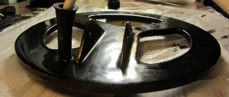
So the dug graphite came in handy))). It weighs about 20 kilograms, apparently from an electrolysis bath, there are 3 holes on top for connecting the cable.
Both coils and the "bed" are shown here. The bed / slipway / substrate is fiberglass, 3 mm thick, mounting the coils on it means that there will be no work on the bottom of the future DD-coil - in fact: put the Rx, Tx coils on the bed, bring them together, fix them with epoxy with fiberglass and EVERYTHING .
In the morning I went to the garden, sawed off a piece of graphite from my “super stash” and took further steps along the coil.
I took a 10 mm drill, drilled a hole and accelerated it
it in a graphite cube, and collected the resulting powder. I wrapped the Rx spool with cotton thread to improve adhesion with PVA glue. I mixed glue with graphite powder in a ratio of 50 to 50 and coated the Rx coil with this mixture. He put the oiled coil on the place designated for it on the “bed” and left it to dry. I won’t coat the Tx coil with antistatic at all.
The Rx coil, coated yesterday with “antistatic”, has dried out. I checked the resistance of the graphite screen:
I cut the screen (you can see the red stripe from the insulating tape) and started working on the connecting cable. After I made the connecting cable (stretched 4 shielded wires and one simple wire into a heat-shrinkable tube) and soldered everything (both coils and the shield wire, see diagram above), then connecting the connector to the ACE 250 and making sure that everything works (the frequency dropped to 11 kHz), reduced the coils to an unbalance of 1 mV and tested a DD coil with a golden earring on the table in comparison with the original coil from the ACE 250. Result.
For a buttoned gold earring it became 17 cm, but it was 13, for an unbuttoned one: it became 7 cm, but it was 5. The longitudinal size of the “asa” coil, 6.5x9″, is 22.5 cm, and mine, size 5x5.8″, is only 12 see. It is interesting that the scale of discrimination has shifted greatly in the area of ferrous metals (expanded), and starting from the USSR nickel, it remained the same and in its place, 5 kopecks. USSR and 50 kop. Ukrainian. - they respond with “bellton”, but the nickel is Ukrainian. from stainless steel it moved one cell to the right (scale cell 2). Pinpoint works. I also noticed that for 25 kopecks in Ukrainian, 50 kopecks in Ukrainian and a nickel of the USSR, the sensitivity, in comparison with the native reel, fell, but for gold it increased, i.e. the gold “stuck out” against the background of the walker, as intended.
If you click on the left frame - this is the first step in filling the coil with epoxy with fiberglass - you can see the “ground” drain from the screen. It is a bare copper wire, 10 cm long, fused in places with a soldering iron into a graphite screen.
In the meantime, I repaired the original “Asin” coil, there were nicks, and with the remaining black putty (epoxy with SAMSUNG laser printer powder) I glued a couple of fiberglass patches to the sensor. My baby is moving towards the finish line, I’ll soon take him out for a walk and breathe some sea air, although I didn’t get it right with the epoxy - it dries slowly. Please note that the Rx and Tx coils were not actually impregnated with epoxy before the wires - this is as intended - this also saves weight, but the main thing is maintaining the highest electrical quality factor Q. We get an armored body made of epoxy resin with fiberglass, but the coils themselves are dry, The epoxy didn't reach them.
Below is a comparison of the main parameters of the new homemade “gold reel” and a small native coil from ASI (I show two screenshots of the specan22 program).
The reel was more or less successful, after checking the new reel made on a nearby beach (it showed 10 cm on the primer in the sand, which made me very happy), I immediately wanted to go to the beach and have a real run with it.
The first vacationers appeared on the city beach of Kerch, so I chose a quiet corner outside it. This place was examined a couple of days earlier with two coils (6.5x9″ and NEL Tornado), however, my homemade baby suddenly began to pull out USSR pennies and Ukrainian nickels. It was clear with Ukrainian stainless steel nickels - previously, if you turned off the first square of the discrimination scale, the device saw them, but did not voice them, because it considered them ferrous metal, and the new coil operating at a frequency of 11 kHz “stretched” the left side of the metal scale (like at Ace 350 Euro) and began to squeak “color” on the stainless steel. But the USSR kopecks really became an indicator of the quality of my reel, because some jumped out from a depth of 15 cm and were clearly missed by me earlier when I was using my original and “Tornado” reels. Despite its small size, the reel showed quite a large coverage, similar to the usual one from the native Asevskaya 6.5x9″ reel (along the center line the coverage was 18 cm for a 10 kopeck coin lying on the sand surface), so I did not have to compact steps when searching.
Then I came across an openwork silver chain. I'm not sure that I could find it with the original Acev coil (I'll have to check). Found a silver chain somewhere here. I liked the sharp sound and sharp reaction to the target, probably characteristic of this type of coil. The clouds began to thicken, a cold breeze blew, and in order to avoid getting caught in the downpour, I drove home.
Modest discoveries made during testing. The gold medallion was raised two days earlier using my native ASE reel, I’m showing it because I also tested my “gold reel” on it.
Here is the frequency response of the coil in comparison with other coils (practical screenshots of the specan22 program of some coils for ASI are shown in comparison with this new-made “gold coil”).
I started the article in December 2013, but I carried out the final test of the reel’s reaction to small gold only at the beginning of June 2014, together with a friend.
This is how the coil showed itself on February 23, 2015.
And here you can see this coil in comparison with the factory coils for the ACE 250.
Shown here and here is the reel in action on the beach in 2022.
— — — — — — — — — — — —
In March 2015, I received questions. I in no way think that there are stupid questions, but I think that there are stupid answers.
Let's start with the first question.
1. Connecting the headphone jack to which contacts, or does it matter?
Answer: no difference. Solder the “jack”, plug it into the input of the computer’s sound card and the probe will begin to receive frequencies emitted by the coils of metal detectors, and the computer, turned into an analyzer, will “figure it out” and show the frequency. Here is a slightly different probe diagram and details of working in the specan22 .
2. How are the wires on the coils soldered? 8 in one or in colors with each other? How did you get 2 exits?
Answer:
This is the future Tx radiating coil (the second Rx coil will be made according to the same principle).
In the main text (see above) I write: “There are 9 turns of this cable, devoid of an outer sheath, i.e. 9 x 8 = 72 turns, respectively, soldered end-to-end.
Let's describe it in more detail.
First, I wound 9 turns of cable on a coffee can (the diameter is approximately the same as a liter glass jar), then I removed the coil, grabbed it in four places with white electrical tape and began to unsolder it. Those. Before I started working on turning it into a single coil of 72 turns, I had 8 separate coils of 9 turns each (or 8 “beginnings” and 8 “ends” lying opposite each other - I separated them with a conventional red line), which I had to connect it into one coil.
Let's now look at this particular picture of the coil, although it is not very good for demonstration.
We take the first “start” vein we come across - for me it’s a green vein (it dives into the coil in the upper half of all “starts” and is indicated by a red arrow), now we find this green vein among the “ends” at the bottom of the coil (i.e. our green vein made 9 turns and finally emerged among the “ends” - I also marked it with a red arrow) and we solder this “end” to the “beginning” of any other vein (if you click on the frame and look closely, you can see that the end of the green vein is soldered with the beginning of some next vein and an insulating tube with an asterisk is put on the splice). Then we find the end of the second vein and connect it to the beginning of a third vein. We will have to do such operations, on record, 7 times, i.e. make 7 splices of cable cores until there is only one “end” left, which has nowhere to solder - in the picture it is a white core with a green streak.
As a result, we get a single coil of 72 turns, the “beginning” of which is a green vein and the “end” is a white vein with a green vein.
I recently saw this picture and took it to my website - this is how you need to join the ends together to get a single coil, it is clear that there are different colors for the beginning and end of the coil.
3. There are 2 outputs from the coil. Which one should I solder on the connector? Or does it matter?
Answer: Each coil has 2 outputs; in order to test the future Tx coil for frequency generation and measure it, the coil needs to be connected to pins 1, 4 of the connector, and the connector must be plugged into the AC. The completed coil will have 4 outputs, the wiring to the connector is shown in the text. For a long time it won’t matter how exactly the ends are soldered - you’ll have already completed the coil, you’ll go to the beach to test it (and do the final mixing operation, as I recommend to the most inquisitive designers) and only then will you need to cross the ends on the connector and test the pinpointer in operation with "colored" targets. In the literature, such a finishing operation is called “phasing” the coils. I don’t need any equipment; opponents cannot do without a separate generator, oscilloscope and other instruments. A correctly phased sensor does not move the pin away from the object, but clearly shows that the target lies at the intersection of the windings.
4. Does the resistor remain on the TX coil after checking on the computer and assembly on the substrate?
Answer: No, I installed this 1.1 Ohm resistor only to estimate the frequency and not accidentally burn out the ACE 250. There are no resistors, capacitors or anything at all on the working coil, just the coils themselves.
5. How to properly check the resistance on a graphite screen? And why cut the graphite screen?
Answer:
The picture shows that I simply pressed the probes to the graphite screen at opposite points of the coil, the device showed a resistance between the probes of slightly more than 1 kOhm - this is quite normal resistance. The screen will work perfectly with a resistance of 10 kOhm. It is designed so that colossal static charges of tens of thousands of volts flow down to the “ground” of the MD, so the resistance of the shielding coating of the Rx coil is not of fundamental importance.
The annular cut is needed to prevent the formation of a closed loop (turn) in the form of a graphite screen. Despite the rather large resistance of the screen, it seems to me that such a cut needs to be made. Different authors think differently. I was getting the most out of this coil at every step, so I made a cut in the screen so that the screen would never be a shorted TURN on a given coil.
6. Is it worth covering the TX coil with a graphite screen?
Answer: I left the Tx transmitting coil without a screen. I believe that the screen will at least slightly reduce the signal that will be “pumped” into the ground. Further tests showed a neutral reaction to static electricity - i.e. It is really enough to shield only the Rx receive coil.
7. What are the dimensions of the reel mounting lugs? What were they made of and what were they glued to? What is the cross on the backing and how was it calculated?
Answer: My understanding was that the lugs were supposed to attach directly to the bed/substrate and not be mechanically connected to the coils. I prepared the seats at the ends of the bed and first glued these 2 ears with some kind of glue, and then reinforced them with epoxy and fiberglass in the process of forming the entire coil. The ears are cut from a sheet of textolite, 0.5 cm thick. The distance between them is not standard for the ACE 250. The ears are clearly visible if you click on the corresponding frames above. The lower rod elbow assembly is made from a garden hose "T" splitter and cut to fit frictionally between the tabs. The cross on the backing means almost nothing, it was just clearly visible through the paper sheet on which I did the initial mixing of the coils and outlined their relative positions.
8. Regarding the cable: did you shrink the heat shrink with a hairdryer? What and how did you attach the cable itself to the reel? Well, the main question: HOW was the cable soldered? They just connected the 4 outputs from the coils and soldered them to the connector, and what did they attach the 5th cable to on the finished coil?
Answers: I heated the heat shrink tube over a regular electric kitchen stove.
The cable simply sank into layers of epoxy with fiberglass and was fixed on the reel.
My cable wiring is better than any factory or homemade reel. Now I will gradually explain why, although I will not describe the physics.
First, I will characterize the wire itself, which formed the basis of the connecting cable: I used 4 identical pieces of shielded MGTF wire and one piece of unshielded MGTF wire, all of them have a length of 1.5 m. This is the best existing multi-core wire (in my 24 it is very thin copper wires with a diameter of 0.08 mm, and its insulation can withstand the temperature of a soldering iron, since it is made of fluoroplastic; its shielding braid (sometimes I just write “screen”) is silver-plated copper, in short, it is an excellent “military” wire).
And secondly, let's turn to the wiring of the connecting cable, which is shown in the blue frame. It can be seen that all the shielded wires are prepared in the same way, as shown in the red frame, namely, the left end has no shield lead (only the wire itself), and the right end has a shield lead, and all such shield leads of the four wires are collected at one point, indicated by a circle. For complete clarity of perception, I’ll add that the cylinder in the red frame is the wire screen, and the signal wire itself runs inside the cylinder, as is usually indicated on most circuits in the world and, of course, the wire is isolated from the shielding braid (screen), the insulator is fluoroplastic film .
All that remains is to deal with the fifth wire, which does not have a screen (but has insulation). Its left end is shown as such a “chicken foot” - in this place the wire has contact with the graphite coating of the Rx coil - the wire there is bare and glued (more precisely, fused with a soldering iron tip) at several points to the graphite screen. No matter how tempting it may be to run this contact through any of the shields of the four wires (and many factory coils sin with this to save copper), I do this with a separate wire (and also of the highest quality).
What do we get as a result of unsoldering the connecting cable? - all ends of all coils are run along shielded wires, each with its own wire, all shielding braids of wires and the wire coming from the shielding shell of the Rx receiving coil are soldered at one point (and then connected through the 5th pin of the connector to the main “ground” on the MD board) .
The resulting homemade cable is wrapped with electrical tape along its entire length and then pulled through a heat-shrinkable tube.
Theoretically, the parameters of the connecting cable can still be improved if you use not just shielded wires, but each of them is additionally insulated along its entire length (my wires had a bare braided shield).
9. Could you tell us in more detail about mixing the coils? Interested in how to connect the tester if the plug and coils are soldered to the cable?
Answer: You need to measure (and reduce to zero) the alternating voltage at the output of the Rx receiving coil and it is advisable to do this in the field. But first you need to test everything on the table in order to make a drawing of the relative position of the coils, and make a bed/substrate based on the drawing. The pins of connector 1, 4 now go to the ASI block and the Tx coil starts generating from it. The induction voltage is induced in the receiving coil Rx and when tuning/mixing the coils should be reduced to a minimum (to all zeros on the tester). In practice, do this: do not touch pins 1, 4, and completely unsolder the Rx coil pins from the pins 2, 3 of the connector and connect the tester to these wires (solder the probes) in the AC voltage measurement mode. After obtaining “zero” voltage at the output of the Rx coil, sketch the relative position of the coils and cut out the bed/substrate based on the drawing. Then glue the Rx coil to it (it should already be in the graphite screen, and the screen is connected by wire to pin 5 of the connector), now you can go to the beach to set the “zero” as accurately as possible, taking into account the influence of the ground. (In the ACE 250 there is no ground detuning, it is set only once “to the average” at the factory, so by making a coil with pre-compensated ground influence, you will significantly improve the MD parameters set by the factory. “Ground roar”, by the way, is tens of times higher than the useful signal ). In the field, you need to first find the abs. a place that is clear of metal debris (your original coil will help you here), then place a new coil on the sand and carry out the “mixing” as at home, on the table, i.e. connect the coil according to the method described above, “reduce” to four zeros on the device, and after “reconciling the coils,” fix their position on the substrate with glue. The tester should be kept away from the coil. To fix the final position of the coils, you should use non-plastic glue (it can “float” when using the coil in the heat), but preferably the “droplet” type, which is sold in small tubes. Upon arrival home, you can already apply the first layer of epoxy with fiberglass.
The lower leg of the rod was made from suitable polyethylene tubing. This friction elbow fits onto an aluminum rod and does not have any other fastening elements. The ends of the knee are reinforced with epoxy and fiberglass.
And one last thing. If I started making this coil now, I would give a much larger allowance for the “bed”. What’s wrong with the fact that it would be the one that would encounter all sorts of obstacles in the way of the coil’s movement? - then with the coil (the protruding edge of the bed/substrate) you could literally dig the sand.
All pictures are clickable.
What is metal discrimination?
Those who are interested in the structure and operating principle of metal detectors often come across the expression “discrimination of metals” when searching for the necessary information. The metal detector's discrimination function determines the direction of the search for a particular group of metal objects. Installing a metal detector to detect non-ferrous metals allows you to ignore iron-containing inclusions in the soil mass.
Units equipped with a display can display a discrimination scale from “0” to “99”. The more the device indicator tends to 0, the lower the electrical conductivity of the found metal object.
In some models, the discrimination line is graduated for types of metals such as iron, nickel, zinc, aluminum, gold, copper and silver. The device can make corrections for the inclusion of ligature in the main composition of the material. The type and amount of alloy in the metal changes its electrical conductivity.
Metals are practically never found in their pure form, so in complex high-level devices there are options that allow you to “ignore” metals such as iron, nickel and aluminum. The metal detector will respond to the detection of gold, silver and copper.
Selective discrimination of metals allows you to reduce the time spent on detecting unnecessary objects and not waste energy on digging unnecessary holes.
Assemble the PIRATE metal detector with your own hands
Members of military historical societies, local historians and treasure hunters are often concerned about finding cheap models of metal detectors.
The desire to assemble a metal detector with your own hands is primarily caused by economic factors. A factory-made finished product is quite expensive. There are models costing up to several tens of thousands of rubles. The media publishes a lot of “recipes” for making homemade devices.
To detect metal-containing objects in the soil, you can make a metal detector with the Pirate circuit.
Pirate is an impulsive metal detector with a simple electronic circuit. The name has nothing to do with sea robbers. The Latin abbreviation consists of two abbreviations: PI (impulse principle) and RAT (name of the author’s website).
Assembly instructions for MI PIRATE
To make a homemade metal detector, you need to prepare several items in advance - a search circle with a coil, an electronic control unit and a holding rod.
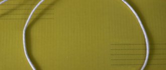
Search Circle
It can be cut from construction plywood, plastic or other dielectric material. The circle is a rim ø 180 – 210 mm with a winding wire (24 – 25 turns) ø 0.5 mm wrapped around it. To increase the detection distance, the search circuit is made ø 260 - 270 mm and wrapped with the same conductor in the amount of 21 - 22 turns.
The recommended search circle sizes and wire parameters are shown in the following table.
| Sensor diameter (circle), mm | Number of turns, pcs. | Ø wire cross-section, mm |
| 120 | 36 | 0,40 |
| 150 | 31 | 0,40 |
| 175 | 28 | 0,40 |
| 200 | 26 | 0,40 |
| 250 | 22 | 0,40 |
| 300 | 20 | 0,50 |
| 400 | 17 | 0,50 |
| 500 | 15 | 0,50 |
Rod holder
Any dielectric length is used as this part. This could be a wooden holder for garden tools, mops, or a polymer tube. A search circle is attached to the lower end of the rod. The housing of the electronic control unit is often mounted at the top. The length of the rod is determined by the owner of the equipment himself - according to his height.
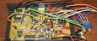
Control block
Various box-shaped plastic products are used for the housing of the electronic unit. The main thing is that the device circuit and batteries can fit freely, but at the same time compactly, in the case. The filling of electronics is assembled on the basis of transistors and microcircuits.
Types of PIRATE metal detector microcircuits
Of all the known circuits of homemade metal detectors, designs are known that are assembled on the following elements:
Ne 555
The main control component of the circuit is the Ne 555 microcircuit. A domestically produced KR1006VI1 microcircuit can be used as an analogue.
PCB option for Ne 555
On transistors
Instead of the Ne 555 microcircuit, some authors propose assembling an electronic control circuit for a metal detector using transistors.
Transistor metal detector printed circuit board option
Tl 0722 and Ne 555
The electronic unit of the Pirate metal detector is assembled on two microcircuits. This greatly simplifies the circuit design of the device.
K561la7
The basis of the MI circuit is the K561la7 chip. The microprocessor consists of 4 sectors. The first two emit a background of a certain frequency, the 3rd element detects the reflected signal from the desired metal object, and the 4th sector compares the level of the output and receiving frequencies.
Different values of these parameters cause a signal to be sent through the amplifier to the speaker of the device. The electronic unit is powered by a Krona battery. Its capacity is enough to use the device for a long time.
Components for assembling the electronic circuit of the Pirate metal detector on K561la7
- Used capacitors are often used, but their capacity must be checked. Ceramic elements work well. To make the circuit you will need the following parts: 100 uF – 1 pc.; 1000 pF – 3 pcs.; 22 pF – 2 pcs.; 300 pF – 1 pc.
- Used fixed resistors are also used by removing them from old circuits. They retain their quality characteristics for many years. 22 Ohm – 1 pc.; 1 kOhm – 1 pc.; 4.7 kOhm – 1 pc.; 10 kOhm – 1 pc.; 470 kOhm – 1 pc.
- It is better to buy variable resistors in an electrical supermarket or at a radio market: 1.5 kOhm - 1 pc., 20 kOhm - 1 pc.
- The K561la7 chip is housed in a protective DIP format housing. The legs are numbered from the notch on the chip body, starting counterclockwise.
- The KT-315 transistor can be replaced with KT3102, BC546, or similar low-frequency elements with similar characteristics. Looking at the front part of the transistor, the terminals are distinguished, from right to left - emitter, collector and base.
- The diode can be selected from such radio components as: kd522B, kd105, kd106. Before soldering, the diode must be ringed in order to accurately distinguish the anode from the cathode.
- You can use headphones from an mp3 player or something similar as a signaling device.
- Power supply: 9 V Krona battery. and contact group.
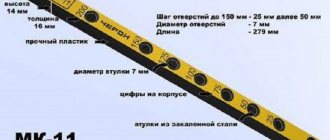
Ways to improve a shovel for a garden: to the sharpness of a knife
The shovel must be well sharpened (or riveted and sharpened). We sharpen (klep) almost from shoulder to shoulder only on the upper, concave side.
Our advice:
If the shovel has been overheated, it cannot be riveted. In this case, we sharpen it on a sharpening machine along the front surface, periodically cooling it in water, and then use a velvet file to bring it to the sharpness of the knife.
As a result, a cutting plane 9-12 mm wide is formed along the edge of the blade. We remove possible burrs.
DIY underwater metal detector
A factory-made model of this type costs a lot of money. Making it yourself is a tempting prospect. With its help, on the seabed among boulders and pebbles, it is quite possible to find dropped valuable objects - rings, chains of gold and silver, etc. With the help of such devices, many artifacts of considerable value have been found.
The structural diagrams of electronic components are the same as for their land-based counterparts, but with some features. This requires ensuring complete sealing of the device. The coil is covered with sealed insulating materials, including the use of epoxy resin.
Small diameter PVC pipes are used as the body. The pipes perform two functions simultaneously - the housing of the electronic unit and the holder rod.
An electronic circuit with connectors for connecting power and the batteries themselves are placed in the pipe. A variable resistor is attached to the head of the connectors to change the sensitivity
It is very important to seal the end hole of the pipe so that the screw of the plug fits into the connection with the head of the variable resistor.
Light indicators – LEDs – are used as metal detection indicators. They have to be powered from the built-in speaker inside the case. When the desired metal enters the field of the coil, the light indicators react with their glow.
Some craftsmen make models with external control of the device using a magnet. By moving a magnet along the body of the metal detector, the operating mode of the device is changed.
Description
Building an underwater metal detector with your own hands is not only easy, but also financially profitable. Using a ready-made device, you can find various objects at the bottom of a river, sea or lake. The unit functions perfectly even in conditions of poor visibility and loud noise. Experts highlight the following features of the metal detector:
- The product compares favorably with the classic unit due to the duration of its stay under water. Some experts prefer to go up to the neck with a metal detector, which is why it is necessary to take into account the optimal immersion depth of the device. It is necessary to provide for all the nuances in advance.
- To make a high-quality underwater metal detector with your own hands, you need to configure the product to search for non-ferrous metals.
- Accurate recognition of tiny objects: rings, earrings, chains. These products are the main prey of underwater seekers.
These three criteria must be taken into account by the master during equipment assembly.