Why was the Volksturm named the best metal detector? The main thing is that the scheme is really simple and really working. Of the many metal detector circuits that I have personally made, this is the one where everything is simple, thorough and reliable! Moreover, despite its simplicity, the metal detector has a good discrimination scheme - determining whether iron or non-ferrous metal is in the ground. Assembling the metal detector consists of error-free soldering of the board and setting the coils to resonance and to zero at the output of the input stage on the LF353. There is nothing super complicated here, all you need is desire and brains. Let's look at the design of the metal detector and the new improved Volksturm circuit with a description.
Since questions arise during the assembly process, in order to save you time and not force you to flip through hundreds of forum pages, here are the answers to the 10 most popular questions. The article is in the process of being written, so some points will be added later.
1. The operating principle and target detection of this metal detector? 2. How to check if the metal detector board is working? 3. Which resonance should I choose? 4. Which capacitors are better? 5. How to adjust resonance? 6. How to reset the coils to zero? 7. Which wire is better for coils? 8. What parts can be replaced and with what? 9. What determines the depth of target search? 10. Volksturm metal detector power supply?
How the Volksturm metal detector works
I will try to briefly describe the principle of operation: transmission, reception and induction balance. The search sensor of the metal detector contains 2 coils – transmitting and receiving. The presence of metal changes the inductive coupling between them (including the phase), which affects the received signal, which is then processed by the display unit. Between the first and second microcircuits there is a switch controlled by pulses of a generator phase-shifted relative to the transmitting channel (i.e. when the transmitter is working, the receiver is turned off and vice versa, if the receiver is turned on, the transmitter is resting, and the receiver calmly catches the reflected signal in this pause).
So, you turned on the metal detector and it beeps. Great, if it beeps, it means many nodes are working. Let's figure out why exactly it beeps. The generator on the u6B constantly generates a tone signal. Next, it goes to an amplifier with two transistors, but the amplifier will not open (it will not let a tone pass) until the voltage at the output u2B (7th pin) allows it to do so. This voltage is set by changing the mode using this same thrash resistor. They need to set the voltage so that the amplifier almost opens and passes the signal from the generator. And the input couple of millivolts from the metal detector coil, having passed through the amplification stages, will exceed this threshold and it will finally open and the speaker will beep.
Now let's trace the passage of the signal, or rather the response signal. At the first stage (1-у1а) there will be a couple of millivolts, up to 50. At the second stage (7-у1B) this deviation will increase, at the third (1-у2А) there will already be a couple of volts. But there is no response everywhere at the outputs.
Video on the topic
Once upon a time, having built several metal detectors of varying degrees of performance with my own hands, I wanted to study how the Arduino circuit works in this direction.
There are several good examples of how to assemble a metal detector with your own hands. However, they usually either require quite a lot of external components to process the analog signal, or the output sensitivity is quite weak.
When we think about pulsed metal detectors, the main topic is how to detect small voltage changes in the signals associated with the search coil. These changes are usually very small. The most obvious approach is to use the ATmega328 analog inputs. But looking at the specs, there are two main problems: they are mostly slow, and the resolution is (in most cases) low.
On the other hand, a microcontroller-based metal detector operates at 16 MHz and has pretty good timing capabilities, namely a resolution of 0.0625 µs when using the clock frequency. So, rather than using an analog input for readout, the simplest way to sense small dynamic voltage changes is to compare the change in voltage drop over time at a fixed reference voltage.
For this purpose, ATmega328 has suitable internal comparator features between D6 and D7. This comparator is capable of triggering an interrupt, allowing events to be processed accurately. Using this along with neatly coded timing routines like millis() and micos(), and using the ATmega328's much higher resolution internal timer, the Arduino is an excellent basis for this kind of metal detector.
So, speaking of the source code - a good start would be to program the internal comparator to "flip" the polarity of the inputs and use the internal counter as fast as possible to change the frequency of the changes.
The final code for Arduino:
Of course, this idea is not entirely new. The bulk of this code may be different. Try searching other sources, such as TPIMD.
How to check if the metal detector board is working
In general, the amplifier and switch (CD 4066) are checked with a finger at the RX input contact at maximum sensor resistance and maximum background on the speaker. If there is a change in the background when you press your finger for a second, then the key and opamps work, then we connect the RX coils with the circuit capacitor in parallel, the capacitor on the TX coil in series, put one coil on top of the other and begin to reduce to 0 according to the minimum reading of the alternating current on the first leg of the amplifier U1A. Next, we take something large and iron and check whether there is a reaction to metal in the dynamics or not. Let's check the voltage at y2B (7th pin), it should change with a thrash regulator + a couple of volts. If not, the problem is in this op-amp stage. To start checking the board, turn off the coils and turn on the power.
1. There should be a sound when the sense regulator is set to maximum resistance, touch the RX with your finger - if there is a reaction, all op-amps work, if not, check with your finger starting from u2 and change (inspect the wiring) of the non-working op-amp.
2. The operation of the generator is checked by the frequency meter program. Solder the headphone plug to pin 12 of the CD4013 (561TM2), carefully removing p23 (so as not to burn the sound card). Use In-lane on the sound card. We look at the generation frequency and its stability at 8192 Hz. If it is strongly shifted, then it is necessary to unsolder the capacitor c9, if even after it is not clearly identified and/or there are many frequency bursts nearby, we replace the quartz.
3. Checked the amplifiers and generator. If everything is in order, but still does not work, change the key (CD 4066).
Which coil resonance to choose?
When connecting the coil into series resonance, the current in the coil and the overall consumption of the circuit increases. The target detection distance increases, but this is only on the table. On real ground, the ground will be felt the more strongly, the greater the pump current in the coil. It is better to turn on parallel resonance, and increase the sense of input stages. And the batteries will last much longer. Despite the fact that sequential resonance is used in all branded expensive metal detectors, in Sturm it is parallel that is needed. In imported, expensive devices, there is a good detuning circuitry from the ground, so in these devices it is possible to allow sequential.
How to adjust the resonance of metal detector coils
The coil, as the best option, is made from plaster floats, glued with epoxy resin from the ends to the size you need. Moreover, its central part contains a piece of the handle of this very grater, which is processed down to one wide ear. On the bar, on the contrary, there is a fork with two mounting ears. This solution allows us to solve the problem of coil deformation when tightening the plastic bolt. The grooves for the windings are made with a regular burner, then zero is set and filled. From the cold end of the TX, leave 50 cm of wire, which should not be filled initially, but make a small coil from it (3 cm in diameter) and place it inside the RX, moving and deforming it within small limits, you can achieve an exact zero, but do this It’s better outside, placing the coil near the ground (as when searching) with GEB turned off, if any, then finally fill it with resin. Then the detuning from the ground works more or less tolerably (with the exception of highly mineralized soil).
Such a reel turns out to be light, durable, little subject to thermal deformation, and when processed and painted it is very attractive. And one more observation: if the metal detector is assembled with ground detuning (GEB) and with the resistor slider located centrally, set zero with a very small washer, the GEB adjustment range is + - 80-100 mV. If you set zero with a large object - a coin of 10-50 kopecks. the adjustment range increases to +- 500-600 mV. Do not chase the voltage when setting up the resonance - with a 12V supply, I have about 40V with a series resonance. In order for discrimination to appear, we connect the capacitors in the coils in parallel (series connection is necessary only at the stage of selecting capacitors for resonance) - for ferrous metals there will be a drawn-out sound, for non-ferrous metals - a short one.
Or even simpler. We connect the coils one by one to the transmitting TX output. We tune one into resonance, and after tuning it, the other. Step by step: Connected, poked a multimeter in parallel with the coil with a multimeter at the alternating volts limit, also soldered a 0.07-0.08 uF capacitor parallel to the coil, look at the readings. Let's say 4 V - very weak, not in resonance with the frequency. We poked a second small capacitor in parallel with the first capacitor - 0.01 microfarads (0.07+0.01=0.08). Let's look - the voltmeter has already shown 7 V. Great, let's increase the capacitance further, connect it to 0.02 µF - look at the voltmeter, and there is 20 V. Great, let's move on - we'll add a couple thousand more peak capacitance. Yeah. It has already started to fall, let's roll back. And so achieve maximum voltmeter readings on the metal detector coil. Then do the same with the other (receiving) coil. Adjust to maximum and connect back to the receiving socket.
The so-called "butterfly"
This nickname was received due to the characteristic shape of the platform on which the inductors are located.
The arrangement of the elements is related to the operating principle. The circuit is made in the form of two generators operating at the same frequency. When identical coils are connected to them, an induction balance is created. As soon as a foreign object with electrical conductivity gets into the electromagnetic field, the balance of the field is destroyed.
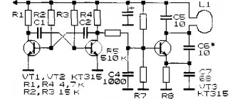
Generators are implemented on NE555 chips. The illustration shows a typical diagram of such a device.
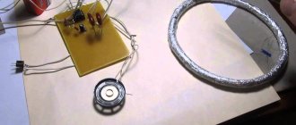
The coil for the metal detector (there are two of them, in the diagram: L1 and L2) is made by hand from wire with a cross section of 0.5–0.7 mm². The ideal option is a transformer winding copper core in varnish insulation (removed from any unnecessary transformer). The characteristics do not have to be maintained with pinpoint precision, under one condition: the coils must be identical.
Approximate parameters: diameter 190 mm, each coil has exactly 30 turns. The assembled product must be monolithic. To do this, the turns are grabbed with a mounting thread and filled with transformer varnish. If this is not done, vibration of the turns will throw the circuit off balance.
Electrical diagram
There are two manufacturing options:
- given the small number of elements, you can assemble it on a breadboard by connecting the legs of the parts using conductors;
- For accuracy and reliability, it is better to etch the board according to the proposed drawing.
Any “snot-based” soldering can fail in the field, and you will be offended for wasting your time.
Just like a transistor metal detector, the NE555 device needs fine tuning before use. The diagram shows three variable resistors:
- R1 is designed to adjust the frequency of the generator and achieve that same balance;
- R2 coarsely adjusts sensitivity;
- Using resistor R3, you can set the sensitivity with an accuracy of 1 cm.
Information: This scheme cannot discriminate against metals. The seeker only makes it clear that the object exists. And by the tone of the signal (based on your experience) you can determine the approximate volume and depth of the deposit.
The power supply is quite universal: 9–12 volts. You can select a battery from an uninterruptible power supply, or assemble a power supply from AAA batteries. A good option is 18650 batteries (they are also used for vaping).
Butterfly setting
The principle of operation is described above, so let’s just look at the technology. We set all resistors to the middle position, and ensure that the synchronization of the generators is disrupted. To do this, we fold the coils in a figure eight and move them relative to each other until the squeaking turns into crackling. This is a synchronization failure.
Read also: Machine for sharpening knives of hair clippers
We fix the rings and rotate the resistor R1 until a steady crackling sound appears at even intervals.
By bringing metal objects to the place where the coils overlap (this is the search point), achieve a steady squeak. The sensitivity is adjusted by resistor R2.
All that remains is adjustment with resistor R3, which is used rather to correct the voltage drop in the power source.
Mechanical part
A do-it-yourself metal detector rod is made from a lightweight plastic pipe or wood. The use of aluminum is undesirable as it will interfere with operation. The circuit and controls can be hidden in a sealed housing (for example, a junction box for wiring).
The butterfly finder is ready to go.
How to zero metal detector coils
To adjust the zero, we connect the tester to the first leg of the LF353 and gradually begin to compress and stretch the coil. After filling with epoxy, the zero will definitely run away. Therefore, it is necessary not to fill the entire coil, but to leave places for adjustment, and after drying, bring it to zero and fill it completely. Take a piece of twine and tie half of the spool with one turn to the middle (to the central part, the junction of the two spools), insert a piece of stick into the loop of the twine and then twist it (pull the twine) - the spool will shrink, catching the zero, soak the twine in glue, after almost complete drying adjust the zero again by turning the stick a little more and fill the twine completely.
Or simpler: The transmitting one is fixed in plastic, and the receiving one is placed 1 cm over the first one, like wedding rings. There will be an 8 kHz squeak at the first pin of U1A - you can monitor it with an AC voltmeter, but it’s better to just use high-impedance headphones. So, the receiving coil of the metal detector must be moved or shifted from the transmitting coil until the squeak at the output of the op-amp subsides to a minimum (or the voltmeter readings drop to several millivolts). That's it, the coil is closed, we fix it.
Which wire is better for search coils?
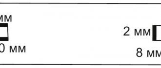
The wire for winding the coils does not matter. Anything from 0.3 to 0.8 will do; you still have to slightly select the capacitance to tune the circuits to resonance and at a frequency of 8.192 kHz. Of course, a thinner wire is quite suitable, it’s just that the thicker it is, the better the quality factor and, as a result, the instinct. But if you wind it 1 mm, it will be quite heavy to carry. On a sheet of paper, draw a rectangle 15 by 23 cm. From the upper and lower left corners, set aside 2.5 cm and connect them with a line. We do the same with the upper right and lower corners, but set aside 3 cm each. We put a dot in the middle of the lower part and a dot on the left and right at a distance of 1 cm.
We take plywood, apply this sketch and drive nails into all the points indicated. We take a PEV 0.3 wire and wind 80 turns of wire. But honestly, it doesn’t matter how many turns. Anyway, we will set the frequency of 8 kHz to resonance with a capacitor. As much as they reeled in, so much they reeled in. I wound 80 turns and a capacitor of 0.1 microfarads, if you wind it, say 50, you will have to put a capacitance of about 0.13 microfarads. Next, without removing it from the template, we wrap the coil with a thick thread - like how wire harnesses are wrapped. Afterwards we coat the coil with varnish. When dry, remove the spool from the template. Then the coil is wrapped with insulation - fum tape or electrical tape. Next - winding the receiving coil with foil, you can take a tape from electrolytic capacitors. The TX coil does not need to be shielded.
Remember to leave a 10mm GAP in the screen, down the middle of the reel. Next comes winding the foil with tinned wire. This wire, together with the initial contact of the coil, will be our ground. And finally, wrap the coil with electrical tape. The inductance of the coils is about 3.5 mH. The capacitance turns out to be about 0.1 microfarads. As for filling the coil with epoxy, I didn’t fill it at all. I just wrapped it tightly with electrical tape. And nothing, I spent two seasons with this metal detector without changing the settings. Pay attention to the moisture insulation of the circuit and search coils, because you will have to mow on wet grass. Everything must be sealed - otherwise moisture will get in and the setting will float. Sensitivity will worsen.
Simple metal detectors from ready-made electrical appliances
A metal detector can be easily built from a radio receiver and equipped with a high-frequency transmitter. The coil consists of 16 turns with a diameter of 12 cm, wire cross-section 0.5 mm². When metal is detected, the signal height changes.
A homemade metal detector made according to a circuit diagram can be no less reliable than a factory-made device. The simplest metal detector can be made without specialized equipment, even without having any experience in working with radio electronics.
What parts can be replaced and with what?
Transistors : BC546 – 3 pcs or KT315. BC556 – 1 piece or KT361 Op amps :
LF353 – 1 piece or exchange for the more common TL072. LM358N – 2 pcs Digital chips: CD4011 – 1 pc CD4066 – 1 pc CD4013 – 1 pc Fixed resistors, power 0.125-0.25 W: 5.6K – 1 pc 430K – 1 pc 22K – 3 pcs 10K – 1 pc 390K – 1 pc 1K – 2 pcs 1.5K – 1pc 100K – 8pcs 220K – 1pc 130K – 2pcs 56K – 1pc 8.2K – 1pc Variable resistors: 100K – 1pc 330K – 1pc Non-polar capacitors: 1nF – 1pc 22nF – 3pcs (22000pF = 22nF = 0.022uF) 22 0nF – 1 piece 1uF – 2 pieces 47nF – 1 piece 10nF – 1 piece Electrolytic capacitors: 220 µF at 16V – 2 pieces
The speaker is miniature. Quartz resonator at 32768 Hz. Two ultra-bright LEDs of different colors.
If you cannot get imported microcircuits, here are domestic analogs: CD 4066 - K561KT3, CD4013 - 561TM2, CD4011 - 561LA7, LM358N - KR1040UD1. The LF353 microcircuit has no direct analogue, but feel free to install LM358N or better TL072, TL062. It is not at all necessary to install an operational amplifier - LF353, I simply increased the gain to U1A by replacing the resistor in the negative feedback circuit of 390 kOhm with 1 mOhm - the sensitivity increased significantly by 50 percent, although after this replacement the zero went away, I had to glue it to the coil in a certain place tape a piece of aluminum plate.
Soviet three kopecks can be sensed through the air at a distance of 25 centimeters, and this is with a 6-volt power supply, the current consumption without indication is 10 mA. And don’t forget about the sockets - the convenience and ease of setup will increase significantly. Transistors KT814, Kt815 - in the transmitting part of the metal detector, KT315 in the ULF. It is advisable to select transistors - 816 and 817 with the same gain. Replaceable with any corresponding structure and power. The metal detector generator has a special clock quartz at a frequency of 32768 Hz. This is the standard for absolutely all quartz resonators found in any electronic and electromechanical watches. Including wrist and cheap Chinese wall/table ones. Archives with a printed circuit board for the Volksturm SMD version and for the Volksturm+GEB (version with manual ground detuning).
What determines the depth of target search?
The larger the diameter of the metal detector coil, the deeper the instinct. In general, the depth of target detection by a given coil depends primarily on the size of the target itself. But as the diameter of the coil increases, there is a decrease in the accuracy of object detection and sometimes even the loss of small targets. For objects the size of a coin, this effect is observed when the coil size increases above 40 cm. Overall: a large search coil has a greater detection depth and greater capture, but detects the target less accurately than a small one. The large coil is ideal for searching for deep and large targets such as treasure and large objects.
According to their shape, coils are divided into round and elliptical (rectangular). An elliptical metal detector coil has better selectivity compared to a round one, because the width of its magnetic field is smaller and fewer foreign objects fall into its field of action. But the round one has a greater detection depth and better sensitivity to the target. Especially on weakly mineralized soils. The round coil is most often used when searching with a metal detector.
Coils with a diameter of less than 15 cm are called small, coils with a diameter of 15-30 cm are called medium, and coils over 30 cm are called large. A large coil generates a larger electromagnetic field, so it has a greater detection depth than a small one. Large coils generate a large electromagnetic field and, accordingly, have greater detection depth and search coverage. Such coils are used to view large areas, but when using them, a problem may arise in heavily littered areas because several targets may be caught in the field of action of large coils at once and the metal detector will react to a larger target.
The electromagnetic field of a small search coil is also small, so with such a coil it is best to search in areas heavily littered with all sorts of small metal objects. The small coil is ideal for detecting small objects, but has a small coverage area and a relatively shallow detection depth.
For universal searching, medium coils are well suited. This search coil size combines sufficient search depth and sensitivity to targets of different sizes. I made each coil about 16 cm in diameter and placed both of these coils in a round stand from an old 15″ monitor. In this version, the search depth of this metal detector will be as follows: aluminum plate 50x70 mm - 60 cm, nut M5-5 cm, coin - 30 cm, bucket - about a meter. These values were obtained in air; in the ground it will be 30% less.
Types of metal detectors
There is a wide range of metal detectors on the market, used in many areas. Below is a list that shows some of the varieties of these devices:
Ground modelDeep metal detectorUnderwater vehicleSecurity deviceIndustrial metal detector
- Ground. These devices are designed for searching with your own hands for scrap metal, jewelry, coins, etc.
- Deep. These devices are used to search for the above-mentioned metal products at great depths.
- Underwater. Devices of this type are designed to operate underwater. They can work at different depths.
- Metal detectors for searching for gold. These devices allow you to find gold and gold jewelry in any environment.
- Security devices. These devices are used to detect metal products on the human body and in luggage. Such devices are made in the form of arches and are installed at the entrance to places with large crowds of people, for example, at train stations, shopping centers, etc.
- Industrial. This equipment is part of conveyor lines. Their main task is to detect metal in other substances. For example, in a mined sand-soil mixture.
- Army. The military uses such devices to detect mines, unexploded shells, bombs, etc. with their own hands. The military calls such devices mine detectors.
- Do-it-yourself devices are most often assembled by novice “treasure hunters”.
The use of modern materials allows us to design and manufacture devices with high accuracy in detecting metals in different environments. The use of microelectronics has made it possible to minimize their overall weight parameters. In addition, the simplicity of the electrical circuit allows you to make a metal detector with your own hands at minimal cost.
Metal detector power supply
Separately, the metal detector circuit draws 15-20 mA, with the coil connected + 30-40 mA, totaling up to 60 mA. Of course, depending on the type of speaker and LEDs used, this value may vary. The simplest case is that power was taken from 3 (or even two) lithium-ion batteries connected in series from a 3.7 V mobile phone and when charging discharged batteries, when we connect any 12-13 V power supply, the charging current starts from 0.8 A and drops up to 50 mA per hour and then you don’t need to add anything at all, although a limiting resistor certainly wouldn’t hurt. In general, the simplest option is a 9V crown. But keep in mind that the metal detector will eat it in 2 hours. But for customization, this power option is just right. Under any circumstances, the crown will not produce a large current that could burn something on the board.
Do-it-yourself metal detector “Terminator 3”: detailed diagram and video instructions for assembly
Another modification of a homemade metal detector is the “Terminator”. DIYers are constantly improving the device, and now the third version of the device is popular, working on the principle of induction balance.
Terminator 3 Scheme
We offer you the most detailed description of the assembly of such a device from folk craftsman Viktor Goncharov.
For your information! For DIY assembly, you can choose a butterfly-shaped metal detector with two circuits. It's a little more complicated, but no less effective.