Helpful information
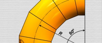
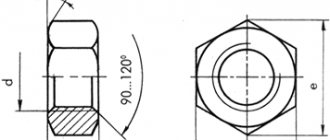
DN - nominal diameter; D – outer diameter at the ends of the outlet; T is the wall thickness of the outlet at the ends of the outer diameter; Tb – wall thickness of bends in non-end sections; C is the size between the centers of the ends of bends with an angle of 180°; B is the size between the plane of the ends and the point of the outer surface of the bends most distant from it with an angle of 180°; F is the size between the plane of one end and the center of the other end of bends with an angle of 90°; H - the size between the end plane and the point of intersection of the tangents to the center line at the points of its intersection with the planes of the ends of the bends with an angle of 45°; R is the radius of curvature of the center line (bending radius) of the bends; W is the size between the end plane and the point of intersection of the tangents to the center line at the points of its intersection with the planes of the ends of bends with an angle of 60°.
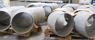
Buy bends, send a request - [email protected] or look at photos of bends according to GOST 17375 in the Catalog.
To calculate transportation costs for transportation of bends:
Weight of 30° bend = weight of 90° bend multiplied by a factor of 0.4.
Weight of 45° bend = weight of 90° bend multiplied by a factor of 0.5.
Weight of 60° bend = weight of 90° bend multiplied by a factor of 0.7.
Weight of 180° bend = weight of 90° bend multiplied by factor 2.
Table 1. Weight and dimensions of bends GOST 17375-01 Version 1 :
| DN | D | T (wall) | F = R | H | WITH | IN | Weight, kg, 1 bend 90° | |||||
| 15 | 21,3 | 2/3,2/4 | 28 | 14 | 56 | 38 | 0,04 | 0,06 | 0,07 | |||
| 20 | 26,9 | 2/3,2/4 | 29 | 14 | 58 | 43 | 0,06 | 0,08 | 0,10 | |||
| 25 | 33,7 | 2,3/3,2/4,5 | 38 | 18 | 76 | 56 | 0,11 | 0,16 | 0,19 | |||
| 32 | 42,4 | 2,6/3,6/5 | 48 | 23 | 96 | 69 | 0,19 | 0,26 | 0,35 | |||
| 40 | 48,3 | 2,6/3,6/5 | 57 | 29 | 114 | 82 | 0,26 | 0,36 | 0,47 | |||
| 50 | 60,3 | 2,9/4/5,6 | 76 | 35 | 152 | 106 | 0,50 | 0,67 | 0,89 | |||
| 65 | 76,1 | 2,9/5/7,1 | 95 | 44 | 190 | 133 | 0,79 | 1,50 | 1,80 | |||
| 80 | 88,9 | 3,2/5,6/8 | 114 | 51 | 228 | 159 | 1,20 | 2,10 | 2,80 | |||
| 100 | 114,3 | 3,6/6,3/8,8 | 152 | 64 | 304 | 210 | 2,40 | 4 | 5,40 | |||
| 125 | 139,7 | 4,0/6,3/10 | 190 | 79 | 380 | 260 | 4,00 | 6,20 | 9,60 | |||
| 150 | 168,3 | 4,5/7,1/11 | 229 | 95 | 457 | 313 | 6,50 | 10 | 15 | |||
| 200 | 219,1 | 6,3/8/12,5 | 305 | 127 | 610 | 414 | 16 | 20 | 31 | |||
| 250 | 273,0 | 6,3/10 | 381 | 159 | 762 | 518 | 25 | 39 | ||||
| 300 | 323,9 | 7,1/10 | 457 | 190 | 914 | 619 | 40 | 56 | ||||
| 350 | 355,6 | 8/11 | 533 | 222 | 1066 | 711 | 57,00 | 78 | ||||
| 400 | 406,4 | 8,8/12,5 | 610 | 254 | 1220 | 813 | 82,00 | 117 | ||||
| 450 | 457,0 | 10,0 | 686 | 286 | 1372 | 914 | 119,00 | |||||
| 500 | 508,0 | 11,0 | 762 | 318 | 1524 | 1016 | 162,00 | |||||
| 600 | 610,0 | 12,5 | 914 | 381 | 1828 | 1219 | 266,00 | |||||
| 700 | 711,0 | — | 1067 | 444 | 2134 | 1422 | — | |||||
| 800 | 813,0 | — | 1219 | 507 | 2238 | — | — | |||||
| 900 | 914,0 | — | 1372 | 570 | 2744 | — | — | |||||
| 1000 | 1016,0 | — | 1524 | 634 | 3048 | — | — | |||||
Table 2. Weight and dimensions of bends GOST 17375-01 Version 2
| DN | D | T (wall) | F = R | W | N | WITH | IN | Weight of 90° bend, kg |
| 25 | 32 | 2 | 38 | 22 | 18 | 76 | 56 | 0,1 |
| 2,5 | 0,2 | |||||||
| 3 | 0,2 | |||||||
| 3,5 | 0,2 | |||||||
| 32 | 38 | 2 | 48 | 28 | 23 | 96 | 69 | 0,2 |
| 2,5 | 0,2 | |||||||
| 3 | 0,2 | |||||||
| 3,5 | 0,3 | |||||||
| 4 | 0,3 | |||||||
| 40 | 45 | 2,5 | 60 | 35 | 25 | 120 | 83 | 0,3 |
| 3 | 0,3 | |||||||
| 3,5 | 0,4 | |||||||
| 4 | 0,4 | |||||||
| 5 | 0,5 | |||||||
| 50 | 57 | 2,5 | 75 | 43 | 80 | 150 | 104 | 0,4 |
| 3 | 0,5 | |||||||
| 3,5 | 0,6 | |||||||
| 4 | 0,7 | |||||||
| 4,5 | 0,7 | |||||||
| 5 | 0,8 | |||||||
| 5,5 | 0,9 | |||||||
| 6 | 1 | |||||||
| 65 | 76 | 3 | 100 | 57 | 41 | 200 | 138 | 0,8 |
| 3,5 | 1 | |||||||
| 4 | 1,1 | |||||||
| 4,5 | 1,3 | |||||||
| 5 | 1,4 | |||||||
| 5,5 | 1,6 | |||||||
| 6 | 1,7 | |||||||
| 7 | 2 | |||||||
| 8 | 2,2 | |||||||
| 80 | 89 | 3 | 120 | 69 | 50 | 240 | 165 | 1,2 |
| 3,5 | 1,4 | |||||||
| 4 | 1,5 | |||||||
| 4,5 | 1,7 | |||||||
| 5 | 1,9 | |||||||
| 5,5 | 2,1 | |||||||
| 6 | 2,3 | |||||||
| 7 | 2,7 | |||||||
| 8 | 3 | |||||||
| 100 | 102 | 3,5 | 150 | 87 | 62 | 300 | 201 | 2,1 |
| 4 | 2,4 | |||||||
| 4,5 | 2,6 | |||||||
| 5 | 2,9 | |||||||
| 6 | 3,4 | |||||||
| 7 | 3,9 | |||||||
| 8 | 4,5 | |||||||
| 9 | 5 | |||||||
| 10 | 5,5 | |||||||
| 108 | 3,5 | 204 | 2,2 | |||||
| 4 | 2,5 | |||||||
| 4,5 | 2,8 | |||||||
| 50 | 3,1 | |||||||
| 6 | 3,6 | |||||||
| 7 | 4,1 | |||||||
| 8 | 4,7 | |||||||
| 9 | 5,3 | |||||||
| 10 | 5,8 | |||||||
| 114 | 3,5 | 207 | 2,2 | |||||
| 4 | 2,6 | |||||||
| 4,5 | 2,9 | |||||||
| 5 | 3,3 | |||||||
| 6 | 3,8 | |||||||
| 7 | 4,4 | |||||||
| 8 | 5 | |||||||
| 9 | 5,7 | |||||||
| 10 | 6,1 | |||||||
| 125 | 133 | 3,5 | 190 | 110 | 79 | 380 | 257 | 3,3 |
| 4 | 3,8 | |||||||
| 4,5 | 4,3 | |||||||
| 5 | 4,8 | |||||||
| 6 | 5,7 | |||||||
| 7 | 6,5 | |||||||
| 8 | 7,4 | |||||||
| 9 | 8,2 | |||||||
| 10 | 9,1 | |||||||
| 11 | 10 | |||||||
| 12 | 11 | |||||||
| 150 | 159 | 4 | 225 | 130 | 93 | 450 | 305 | 5,4 |
| 4,5 | 6,1 | |||||||
| 5 | 6,7 | |||||||
| 6 | 8,1 | |||||||
| 7 | 9,4 | |||||||
| 8 | 11 | |||||||
| 9 | 12 | |||||||
| 10 | 13 | |||||||
| 11 | 14 | |||||||
| 12 | 16 | |||||||
| 13 | 17 | |||||||
| 14 | 18 | |||||||
| 168 | 4 | 5,6 | ||||||
| 4,5 | 6,4 | |||||||
| 5 | 7,1 | |||||||
| 6 | 8,5 | |||||||
| 7 | 9,8 | |||||||
| 8 | 11,2 | |||||||
| 9 | 12,5 | |||||||
| 10 | 14 | |||||||
| 11 | 15 | |||||||
| 12 | 16 | |||||||
| 13 | 17,5 | |||||||
| 14 | 19 | |||||||
| 200 | 219 | 5 | 300 | 173 | 124 | 600 | 410 | 13 |
| 6 | 15 | |||||||
| 7 | 17 | |||||||
| 8 | 20 | |||||||
| 9 | 22 | |||||||
| 10 | 25 | |||||||
| 11 | 27 | |||||||
| 12 | 29 | |||||||
| 13 | 32 | |||||||
| 14 | 34 | |||||||
| 15 | 37 | |||||||
| 16 | 39 | |||||||
| 17 | 42 | |||||||
| 18 | 44 | |||||||
| 250 | 273 | 6 | 375 | 217 | 155 | 750 | 512 | 23 |
| 7 | 27 | |||||||
| 8 | 31 | |||||||
| 9 | 35 | |||||||
| 10 | 39 | |||||||
| 11 | 43 | |||||||
| 12 | 46 | |||||||
| 13 | 50 | |||||||
| 14 | 54 | |||||||
| 15 | 58 | |||||||
| 16 | 61 | |||||||
| 17 | 66 | |||||||
| 18 | 70 | |||||||
| 20 | 78 | |||||||
| 22 | 85 | |||||||
| 300 | 325 | 7 | 450 | 260 | 186 | 900 | 613 | 39 |
| 8 | 45 | |||||||
| 9 | 50 | |||||||
| 10 | 56 | |||||||
| 11 | 61 | |||||||
| 12 | 66 | |||||||
| 13 | 72 | |||||||
| 14 | 77 | |||||||
| 15 | 82 | |||||||
| 16 | 87 | |||||||
| 17 | 92 | |||||||
| 18 | 96 | |||||||
| 20 | 107 | |||||||
| 22 | 118 | |||||||
| 24 | 130 | |||||||
| 26 | 141 | |||||||
| 28 | 150 | |||||||
| 350 | 377 | 9 | 525 | 303 | 217 | 1050 | 714 | 68 |
| 10 | 75 | |||||||
| 11 | 83 | |||||||
| 12 | 90 | |||||||
| 13 | 97 | |||||||
| 14 | 104 | |||||||
| 15 | 112 | |||||||
| 16 | 119 | |||||||
| 18 | 133 | |||||||
| 20 | 147 | |||||||
| 22 | 161 | |||||||
| 24 | 175 | |||||||
| 26 | 188 | |||||||
| 28 | 201 | |||||||
| 30 | 214 | |||||||
| 32 | 228 | |||||||
| 400 | 426 | 8 | 600 | 346 | 248 | 1200 | 813 | 78 |
| 9 | 87 | |||||||
| 10 | 97 | |||||||
| 11 | 107 | |||||||
| 12 | 117 | |||||||
| 13 | 126 | |||||||
| 14 | 135 | |||||||
| 15 | 145 | |||||||
| 16 | 154 | |||||||
| 17 | 164 | |||||||
| 18 | 173 | |||||||
| 20 | 192 | |||||||
| 22 | 210 | |||||||
| 24 | 230 | |||||||
| 26 | 249 | |||||||
| 28 | 268 | |||||||
| 30 | 286 | |||||||
| 32 | 306 | |||||||
| 34 | 324 | |||||||
| 500 | 530 | 9 | 750 | 433 | 310 | 1500 | 1015 | 138 |
| 10 | 153 | |||||||
| 11 | 168 | |||||||
| 12 | 183 | |||||||
| 13 | 198 | |||||||
| 14 | 212 | |||||||
| 15 | 227 | |||||||
| 16 | 242 | |||||||
| 17 | 256 | |||||||
| 18 | 270 | |||||||
| 20 | 298 | |||||||
| 22 | 327 | |||||||
| 24 | 356 | |||||||
| 26 | 385 | |||||||
| 28 | 413 | |||||||
| 30 | 440 | |||||||
| 32 | 467 | |||||||
| 34 | 494 | |||||||
| 36 | 520 | |||||||
| 600 | 630 | 9 | 900 | 519 | 373 | 1800 | 1215 | 198 |
| 10 | 219 | |||||||
| 11 | 245 | |||||||
| 12 | 261 | |||||||
| 13 | 282 | |||||||
| 14 | 302 | |||||||
| 15 | 324 | |||||||
| 16 | 345 | |||||||
| 17 | 366 | |||||||
| 18 | 387 | |||||||
| 20 | 429 | |||||||
| 22 | 471 | |||||||
| 24 | 513 | |||||||
| 26 | 554 | |||||||
| 28 | 595 | |||||||
| 30 | 636 | |||||||
| 32 | 678 | |||||||
| 700 | 720 | 9 | 1000 | 577 | 404 | 2000 | 1360 | 248 |
| 10 | 275 | |||||||
| 11 | 302 | |||||||
| 12 | 329 | |||||||
| 13 | 356 | |||||||
| 14 | 383 | |||||||
| 15 | 410 | |||||||
| 16 | 436 | |||||||
| 17 | 462 | |||||||
| 18 | 489 | |||||||
| 20 | 542 | |||||||
| 22 | 595 | |||||||
| 24 | 647 | |||||||
| 26 | 698 | |||||||
| 28 | 750 | |||||||
| 30 | 801 | |||||||
| 32 | 852 | |||||||
| 800 | 820 | 9 | 1200 | 693 | 485 | 2400 | 1610 | 339 |
| 10 | 376 | |||||||
| 11 | 413 | |||||||
| 12 | 450 | |||||||
| 13 | 487 | |||||||
| 14 | 524 | |||||||
| 15 | 561 | |||||||
| 16 | 598 | |||||||
| 17 | 636 | |||||||
| 18 | 670 | |||||||
| 20 | 743 | |||||||
| 22 | 815 | |||||||
| 24 | 887 | |||||||
| 26 | 959 | |||||||
| 28 | 1030 | |||||||
| 30 | 1101 | |||||||
| 32 | 1171 |
Examples of symbols for bends according to GOST 17375-2001:
Bend 90°, version 2, diameter 219 mm, wall thickness 8 mm, made of steel grade 09G2S: Bend 90-2-219x8-09G2S GOST 17375-2001
Bend 45°, version 1, diameter 60.3 mm, wall thickness 2.9 mm, made of steel grade 20: Bend 45-1-60.3x2.9-20 GOST 17375-2001
Table 3. Weight and dimensions of bends GOST 30753- 01 Version 1
| DN | D | T (wall) | F | WITH | IN | Weight, kg, 1 bend 90° |
| 50 | 60,3 | 4,0 | 51 | 102 | 81 | 0,44 |
| 65 | 76,1 | 5,0 | 63 | 127 | 102 | 0,87 |
| 80 | 88,9 | 5,6 | 76 | 152 | 121 | 1,40 |
| 100 | 114,3 | 6,3 | 102 | 203 | 159 | 2,60 |
| 125 | 139,7 | 6,3 | 127 | 254 | 197 | 4,10 |
| 150 | 168,3 | 7,1 | 152 | 305 | 237 | 6,70 |
| 200 | 219,1 | 8,0 | 203 | 406 | 313 | 13,00 |
| 250 | 273,0 | 10,0 | 254 | 508 | 391 | 26,00 |
| 300 | 323,9 | 10,0 | 305 | 610 | 467 | 37,00 |
| 350 | 355,6 | 11,0 | 356 | 711 | 533 | 52,00 |
| 400 | 406,4 | 12,5 | 406 | 813 | 610 | 77,00 |
| 450 | 457,0 | — | 457 | 914 | 686 | — |
| 500 | 508,0 | — | 508 | 1016 | 762 | — |
| 600 | 610,0 | — | 610 | 1220 | 914 | — |
Table 4. Weight and dimensions of bends GOST 30753-01 Version 2
| DN | D | T | F = R | W | H | WITH | B | Weight of bend θ = 90°, kg |
| 50 | 57 | 4 | 50 | 29 | 21 | 100 | 79 | 0,4 |
| 5 | 0,5 | |||||||
| 6 | 0,6 | |||||||
| 65 | 76 | 5 | 65 | 37 | 27 | 130 | 103 | 0,9 |
| 6 | 1,1 | |||||||
| 7 | 1,2 | |||||||
| 80 | 89 | 5 | 80 | 46 | 33 | 160 | 125 | 1,3 |
| 6 | 1,6 | |||||||
| 7 | 1,8 | |||||||
| 8 | 2,1 | |||||||
| 100 | 102 | 5 | 100 | 58 | 41 | 200 | 151 | 1,9 |
| 6 | 2,3 | |||||||
| 8 | 3,0 | |||||||
| 10 | 3,7 | |||||||
| 108 | 5 | 154 | 2,1 | |||||
| 6 | 2,4 | |||||||
| 8 | 3,1 | |||||||
| 10 | 3,9 | |||||||
| 114 | 5 | 203 | 159 | 2,2 | ||||
| 6 | 2,5 | |||||||
| 8 | 3,3 | |||||||
| 10 | 4,1 | |||||||
| 125 | 133 | 5 | 125 | 72 | 52 | 250 | 192 | 3,0 |
| 6 | 3,6 | |||||||
| 8 | 4,9 | |||||||
| 10 | 6,1 | |||||||
| 12 | 7,3 | |||||||
| 150 | 159 | 5 | 150 | 87 | 62 | 300 | 230 | 4,5 |
| 6 | 5,4 | |||||||
| 8 | 7,1 | |||||||
| 10 | 8,7 | |||||||
| 12 | 11,0 | |||||||
| 14 | 12,0 | |||||||
| 168 | 5 | 234 | 4,7 | |||||
| 6 | 5,6 | |||||||
| 8 | 7,5 | |||||||
| 10 | 9,4 | |||||||
| 12 | 11,0 | |||||||
| 14 | 13,0 | |||||||
| 200 | 219 | 7 | 200 | 115 | 83 | 400 | 310 | 12,0 |
| 8 | 13,0 | |||||||
| 10 | 16,0 | |||||||
| 12 | 19,0 | |||||||
| 16 | 25,0 | |||||||
| 18 | 29,0 | |||||||
| 250 | 273 | 9 | 250 | 158 | 103 | 500 | 387 | 24,0 |
| 10 | 26,0 | |||||||
| 12 | 31,0 | |||||||
| 16 | 42,0 | |||||||
| 18 | 47,0 | |||||||
| 20 | 52,0 | |||||||
| 22 | 57,0 | |||||||
| 24 | 60,0 | |||||||
| 300 | 325 | 9 | 300 | 173 | 124 | 600 | 463 | 34,0 |
| 10 | 37,0 | |||||||
| 12 | 45,0 | |||||||
| 14 | 52,0 | |||||||
| 16 | 59,0 | |||||||
| 18 | 67,0 | |||||||
| 20 | 74,0 | |||||||
| 22 | 81,0 | |||||||
| 24 | 89,0 | |||||||
| 26 | 96,0 | |||||||
| 28 | 102,0 | |||||||
| 350 | 377 | 10 | 350 | 202 | 145 | 700 | 539 | 47,0 |
| 12 | 57,0 | |||||||
| 16 | 76,0 | |||||||
| 18 | 85,0 | |||||||
| 20 | 94,0 | |||||||
| 24 | 113,0 | |||||||
| 26 | 122,0 | |||||||
| 30 | 141,0 | |||||||
| 400 | 426 | 10 | 400 | 231 | 166 | 800 | 613 | 64,0 |
| 12 | 77,0 | |||||||
| 16 | 103,0 | |||||||
| 18 | 116,0 | |||||||
| 22 | 142,0 | |||||||
| 24 | 155,0 | |||||||
| 26 | 167,0 | |||||||
| 28 | 180,0 | |||||||
| 32 | 206,0 | |||||||
| 34 | 219,0 | |||||||
| 36 | 130,0 | |||||||
| 500 | 530 | 9 | 500 | 289 | 207 | 1000 | 765 | 92,0 |
| 10 | 102,0 | |||||||
| 12 | 122,0 | |||||||
| 14 | 143,0 | |||||||
| 16 | 161,0 | |||||||
| 18 | 184,0 | |||||||
| 20 | 204,0 | |||||||
| 22 | 223,0 | |||||||
| 24 | 243,0 | |||||||
| 26 | 262,0 | |||||||
| 28 | 282,0 | |||||||
| 30 | 300,0 | |||||||
| 32 | 320,0 | |||||||
| 34 | 340,0 | |||||||
| 36 | 365,0 | |||||||
| 600 | 630 | 9 | 600 | 346 | 248 | 1200 | 915 | 131,0 |
| 10 | 146,0 | |||||||
| 12 | 174,0 | |||||||
| 14 | 200,0 | |||||||
| 16 | 230,0 | |||||||
| 18 | 261,0 | |||||||
| 20 | 290,0 | |||||||
| 22 | 319,0 | |||||||
| 24 | 346,0 | |||||||
| 26 | 371,0 | |||||||
| 28 | 400,0 | |||||||
| 30 | 428,0 | |||||||
| 32 | 460,0 | |||||||
| 34 | 489,0 | |||||||
| 36 | 518,0 | |||||||
| 700 | 720 | 9 | 700 | 405 | 283 | 1400 | 1060 | 174,0 |
| 10 | 193,0 | |||||||
| 12 | 230,0 | |||||||
| 14 | 268,0 | |||||||
| 16 | 306,0 | |||||||
| 18 | 343,0 | |||||||
| 20 | 380,0 | |||||||
| 22 | 416,0 | |||||||
| 24 | 453,0 | |||||||
| 26 | 489,0 | |||||||
| 28 | 525,0 | |||||||
| 30 | 561,0 | |||||||
| 32 | 596,0 | |||||||
| 34 | 632,0 | |||||||
| 36 | 667,0 | |||||||
| 800 | 820 | 9 | 800 | 462 | 324 | 1600 | 1220 | 226,0 |
| 10 | 251,0 | |||||||
| 12 | 301,0 | |||||||
| 14 | 350,0 | |||||||
| 16 | 399,0 | |||||||
| 18 | 447,0 | |||||||
| 20 | 496,0 | |||||||
| 22 | 544,0 | |||||||
| 24 | 592,0 | |||||||
| 26 | 640,0 | |||||||
| 28 | 687,0 | |||||||
| 30 | 734,0 | |||||||
| 32 | 781,0 | |||||||
| 34 | 828,0 | |||||||
| 36 | 874,0 | |||||||
| Notes 1 Weight is for reference only. 2 The mass of bends with θ = 60° and θ = 45° is 1.5 and 2 times less, respectively, and the mass of bends with θ = 180° is 2 times more than indicated. | ||||||||
Source Design, Pipeline
December 16, 2022
Back
GOST 17375-2001 Status
| Designation: | GOST 17375-2001 |
| Status: | active |
| Type: | GOST |
| Russian name: | Seamless welded pipeline parts made of carbon and low-alloy steel. Steeply curved bends, type 3D (R=1.5 DN). Design |
| English name: | Carbon and low-alloy steel butt-welding fittings. Sharply curved bends type 3D (R=1.5 DN). Design |
| Date of text update: | 06.04.2015 |
| Description update date: | 21.04.2018 |
| Publication date: | 14.01.2010 |
| Effective date: | 01.01.2003 |
| Last modified date: | 11.01.2018 |
| Reissue: | reissue with changes 1 |
| Area and conditions of application: | This standard applies to seamless welded elbows |
| Instead: | GOST 17375-83 |
| List of changes: | No. 1 from (reg.) “Validity period extended” |
GOST 17375-01 You can view and download at the following link - GOST 17375-01
Material for making bends
Most often, bends are made of steel, this is largely due to the loads that the part will have to withstand. The steel for making bends can be alloyed, carbon, or stainless.
Steel can withstand large pressure differences, is suitable for unfavorable climatic conditions, and is resistant to corrosion. Different steels for making bends have their own advantages. For example, 12x18n10t has increased resistance to corrosion, and steel 09g2s is suitable for pipelines located in cold or moderately cold climates.
Alloy steel bends can operate at temperatures from -60 to +40 degrees Celsius. Such parts are suitable for use in pipelines located in cold climates.
If the working environment is aggressive, it is better to use GOST 30753-2001 bends made of stainless or alloy steel. Carbon steel is suitable for general purpose piping.
Steel bends work with steam, hot water, chemically active substances, alkaline media and acids. The main important characteristic of parts for such a pipeline is corrosion resistance, and steel bends meet these requirements. In some cases, galvanized steel parts are suitable for the job. Their inner layer is additionally protected from corrosion by a layer of zinc.
Also, for some pipelines, bends are made of low-density polyethylene and polyvinyl chloride.
Polymer elbows are suitable for mild operating conditions. They cannot be used in pipelines with an aggressive working environment or in unfavorable conditions.
Bends GOST 30753-2001 and other similar parts have several advantages. They are versatile and suitable for a wide variety of systems to change the direction of pipes. Steel bends are resistant to climate conditions - temperature changes or precipitation. At the same time, the price of bends is always affordable. And the GOST requirements, according to which parts are manufactured, ensure their safe and efficient use.
|
A program for calculating, constructing and printing life-size bend patterns
To repair pipelines, it is often necessary to replace the branch. To manufacture it in a workshop, you need to know its characteristics:
- D is the diameter of the outlet (equal to the outer diameter of the connected pipes).
- R is the radius of the outlet (determined by a design specialist based on local conditions).
- Y—retraction angle (determined by a design specialist based on local conditions).
- N is the number of tap elements (outer ones inclusive). Determines the smoothness of direction changes.
If only the rotated angle between the pipes α > 90° is known, then Y = 180 - α.
If this data is provided to you, we will make an allotment based on the drawings. If any data is missing, we make a copy of the allotment.
How to make a welded bend according to the drawings?
Welded bends, consisting of links and cups, are made of pipes or sheet material, which are pre-marked in order to determine the mating lines along which the elements are cut, then joined and welded.
The template is made and marked according to it as follows: on a sheet of paper, cardboard, paronite or roofing felt, a scan of the entire element of the shaped part or its end with the mating line is drawn. Then the development is cut with scissors, forming a template, which is applied to the marked pipe and outlined with chalk; The required element or part of it is cut out using chalk.
The Excel table we offer allows you to obtain the dimensions for constructing a template (development) for the manufacture of outlet elements with any !!! characteristics.
Enter the characteristics of the bend and the length of the segments on the X axis into the yellow cells of the table and you will instantly receive the ordinates and abscissas of the construction points.
Transfer these points to paronite or cardboard and smoothly connect them together.
You have received a pattern for the extreme half-link of the bend.
We mirror the scan of the outer half-link relative to the horizontal axis and get the well-known “fish”. With its help, the middle elements of the outlet are marked.
A correctly made pattern, folded into a ring and laid on a plane, has no gaps.
When marking the links, it is necessary to keep in mind the following:
1. The number of links n, neck width b, outlet radius R must correspond to the technical conditions and the place where the fitting is installed. For example, “Technical conditions for the production and acceptance of work on the installation of gas networks in cities, towns and industrial enterprises” SN 117-60, paragraph 159, stipulate that the radii of welded bends must be at least the same diameter. The “Technical conditions for the production and acceptance of work on the installation of heating networks” SN 108-60, paragraph 125c, states that the radii of welded bends must be at least 1.5 diameters. The same TU SN 108-60, paragraph 126, stipulates that the neck width b must be at least 50 mm.
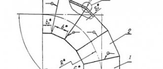
2. When using the proposed marking methods, there should be no waste or unused pipes. When cutting links from sheet material, in order to use it rationally, the links should be marked so that they are located on the sheet, as shown in Fig. 2. In this case, after cutting and welding the links, the welds will be located both on the neck and on the back of the link or cup. In cases where bends are made of thick sheet material (more than 2 mm thick), it is recommended to pre-roll the material and turn it into a pipe, and then mark, cut and weld the necessary elements.
Tip 1
. Never trust the GOST pipe diameter. Before making the template, determine the length of the template. Wrap the selected material tightly around the pipe, make a notch, unfold the future template and measure the circumference. By changing the pipe diameter value when entering the table, ensure that the measured length matches the calculated length of the template. On a pipe intended for making a branch, apply diametrically opposed generatrices with chalk. Markings and welding should be carried out with precise reference to them.
Tip 2.
Very important!!!
Pipe cutting should be done so that the cutter flame (oxygen jet) moves in the plane of the intended section. Imagine cutting sausage with a knife. This should be the cutting plane. But in practice, the cutter is always held perpendicular to the pipe and on the necks of the cut links you get flaws: on the small neck there is an undercut of metal, and on the large neck there is a “bump”. When the sectors are joined with these “bumps”, a void appears in the middle, depending on the thickness of the pipe wall. If the welder decides to leave the “bumps” and weld the voids, then by placing “bump” on “bump” you will inevitably change the length of the large neck and, as a result, the angle of withdrawal. The product will be damaged. “Blow off” the bumps or grind them off, make finishing touches by checking the template and then cut the edges for welding. Place the element on a plane - the gaps should be minimal.
Tip 3.
The links are connected according to Fig. 3, so that the links indicated by numbers are joined into one group, and by letters - into another group; then, with one turn and welding, both groups are connected. This achieves better alignment of the links, especially in cases where the pipes have some, although permissible, deviations from the correct circle in the cross-section.
The attachment contains a table with a macro that can build a product template with the characteristics you specify in full size.
Print it out and use it.
Watch the demo video
(Drawings, descriptions, formulas were taken from the book by I.Kh. Brodyansky “Marking of welded shaped parts of pipelines”, 1963)
Upon successful payment, you will immediately receive a link to download the worksheet.
I guarantee decency! Good luck in job!
Buy bends made of stainless steel according to GOST 17375-2001
The Carbon Group company offers to buy bends in accordance with GOST 17375-01 on favorable terms. Our company has the ability to produce plugs from other steel grades, incl. 15Х5М, 08Х18Н10Т, 12Х18Н10Т, based on operating conditions, according to regulatory and technical documentation approved in the prescribed manner. Terms of purchase and delivery are agreed upon in advance. To find out prices, you can leave a request by filling out the form below or calling tel. ☎ ☎
Bends GOST 30753-2001: areas of application
The main function of bends is to change the direction of flow. Therefore, they are mounted on the pipe in the place where the pipeline must change direction. Installation of bends is possible using welding, flange and threaded connections.
Bends are used for assembling oil pipelines, at metallurgical and energy enterprises. They are also used in the housing and communal services system. These parts are necessary when installing water pipes and heating systems.
The bends are suitable for the operation of pipelines that pump liquid media, as well as for transporting gas, chemicals and steam.
The bends are connected to other parts by welding or threading. This greatly expands their use cases.
For example, seamless steep bends can be used in oil and gas chemical pipelines. Thanks to installation by welding, the entire pipeline system is sealed.
The bends can be operated at temperatures up to 450 degrees Celsius. The lowest operating temperatures are -70 degrees Celsius.
The parts are made in a variety of diameters. For example, DN 15, DN 25, DN 40, DN 45. Also, bends can have a larger diameter - from DN 426 and above.
Thanks to these characteristics and the bending angle (possible from 3 to 90 degrees), bends are used in a wide variety of pipelines. They are suitable for pipes with different wall thicknesses. This expands the possibilities of their use.
Examples of using bends
They are often used when wiring communications for various purposes. Only the types of taps differ. For example, in a pipeline with a large cross-section there will be high pressure for the movement of the working fluid. And in this case, steeply curved seamless bends or bent parts made of stainless steel are suitable.
In the housing and communal services sector and for other household communications, steeply curved and bent bends can also be used.
Bends are installed not only on pipelines that transport gases, oil, water and other working media. The parts are also used in ventilation systems and air purification systems.