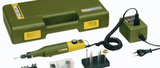
I decided to build my first pulse metal detector, Clone PI-W, and now it comes to making a mono search coil. And since I am currently experiencing some financial difficulties, I was faced with the difficult task of making a reel myself from the cheapest materials possible.
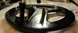
Looking ahead, I’ll say right away that I coped with the task. As a result, I got this sensor:
By the way, the resulting ring coil is perfect not only for Clone, but also for almost any other impulse generator (Koschei, Tracker, Pirate).
Next, I will tell you how to make a search coil for a metal detector with your own hands, spending less than 500 rubles on it.
I will tell you in great detail, since the devil is often in the details. Moreover, there are a dime a dozen short stories about making reels on the Internet (like, take this, then cut it off, wrap it, glue it and you’re done!) But you start doing it yourself and it turns out that the most important things were mentioned in passing, and some things were completely forgotten to say ... And it turns out that everything is more complicated than it seemed at the very beginning.
This won't happen here. Ready? Go!
Idea
The easiest design for me to make on my own seemed to be this: take a disk made of sheet material ~4-6 mm thick. The diameter of this disk is determined by the diameter of the future winding (in my case it should be 21 cm).
Then we glue two disks of slightly larger diameter to this pancake on both sides to make a bobbin for winding wire. Those. such a coil greatly increased in diameter, but flattened in height.
For clarity, I’ll try to depict this in a drawing:
I hope the main idea is clear. Just three disks glued together over the entire area.
Assembling the Pirate metal detector:
First, of course, you need to prepare the board. To do this, open the Sprint-Layout program and print a blank of our future board, then transfer the drawing in any convenient way onto the prepared board, etch it and drill holes for the parts. I use LUT technology, although I don’t have a laser printer, I do it at work.
But when it is not possible to print on a laser printer, you can make a drawing on an inkjet printer, then cut the fiberglass of the desired shape, attach the drawing to the board and mark the holes with a sharp object, then drill and draw the tracks manually with a permanent marker. Well, or translate it using a carbon copy.
Be sure to clean the board with fine sandpaper and degrease it with acetone before applying the design, so the image will transfer well and the etching process will be faster and more reliable. After the board is etched, you need to wipe off the toner or marker again with acetone and rub it a little with sandpaper.
Then we take a soldering iron and tin the tracks with tin. After tinning, be sure to wipe off excess rosin with acetone in order to avoid problems in the future. If desired, you can ring the tracks.
Now you need to solder all the parts onto the board. To do this, we also open the signet in the Sprint-Layout program and look at where the parts are located. I strongly advise you to install sockets for microcircuits, just in case. First of all, solder the jumpers, there are 2 of them in the circuit, and one is located under the NE555 chip, so if you forget about it, it will be difficult to find the fault, since I’m sure you won’t remember these jumpers! Legs from resistors can be used as a jumper.
When all the parts are in place, all that remains is to solder the taps to the variable resistors, coil, speaker and power.
A correctly assembled circuit starts working immediately, without any settings! The coil, as I said above, is wound on a 19-22 cm frame and contains 25 turns. To search for smaller objects, you can wind a coil less than 15 cm - 17 turns or 10 cm - 13 turns. To search for ferrous metal, it is of course better to use a coil with a diameter of 19 cm.
I want to say a few words about the tonality of the sound. He seemed too rude to me. You can change the tonality by selecting capacitor C1, I replaced it with 47nf and the sound became higher.
It is better to take a speaker like 3GDSH TRYD 4070-02 8 Ohm so the sound will be much more powerful, I replaced the old speaker in my metal detector with this one. The speakers from the headphones also perform very well.
A link to the printed circuit board, as well as a list of parts needed to assemble the Pirate, which can be bought very cheaply on AliExpress with free shipping, are at the end of the video article!
And finally, a video of the Pirate metal detector in action:
Material selection
I planned to use plexiglass as the material. It is perfectly processed and glued with dichloroethane. But, unfortunately, I couldn’t find it for free.
All sorts of collective farm materials such as plywood, cardboard, bucket lids, etc. I immediately discarded them as unsuitable. I wanted something strong, durable and preferably waterproof.
And then my gaze turned to fiberglass...
It's no secret that fiberglass (or glass mat, fiberglass) is used to make whatever your heart desires. Even motor boats and car bumpers. The fabric is impregnated with epoxy resin, given the desired shape and left until completely cured. The result is a durable, water-resistant, easy-to-handle material. And this is exactly what we need.
So, we need to make three pancakes and ears for attaching the barbell.
Housing for metal detector
After assembling a metal detector or other radio circuits, the question arises: what kind of housing to come up with for it and where to get it. I found a simple and inexpensive solution to this problem. As a housing, I will use the box for the starter machine and place the Pirate metal detector in it. Below I will provide detailed instructions and a description of how to make a housing for a metal detector.
So, to make a housing for a metal detector, you need to buy, as I said above, boxes and automatic light starters, it is not expensive, around 25-50 rubles.
Since I will be making a housing for the Pirate metal detector, I need to install two variable resistors on it, a power switch and a block for connecting the coil and power source. First, I’ll install the resistors; to do this, we attach them to the body with twisters and mark the marks for the holes with a marker; I decided to install them on the top part.
Then we take a drill to the diameter of the resistor handles and drill holes. Plastic drills very well, so if you don't have the right drill bit, you can use a circular motion to drill out the holes!
Now you need to make a hole for the switch, I decided to install it on the front side of the case, it’s more convenient, and it looks good. To do this, we also take a suitable drill and make a hole.
Next you need to install on the back of the case the power connectors and coils. I took the usual Chinese ones, ordered on Aliexspree, by the way they arrived quickly and of very good quality, I took 50 pieces, there were about 20 left. If anyone is interested, here is a link to the product! And they look like this:
To install the pads, you need to mark 4 points for the legs.
Then take a small drill and drill holes. Then insert the pads there. I took a drill slightly smaller than the diameter of the legs, this is necessary so that the block fits tightly into the holes and stays there without glue. After the block is installed, the legs will stick out inside the case, and I will solder the wires to them. If you don’t have such a block, then there are a lot of other options; by the way, in stores where they sell light bulbs, wires, etc., there are other types of blocks, they can also be used. In general, you need to experiment!
Now you can install all parts of the circuit in their places. Let's start with resistors:
Then we will install the switch, having first soldered to it one wire from the circuit (I took the negative one), the second wire from the switch will go to the block.
And solder the wires to the pads, not forgetting to indicate with a marker on the back side where the plus goes and where the minus goes!
Now we install the speaker. To mount the speaker, I used glue gun, coated the speaker on the front side in four places and glued it inside the case.
Next, we solder the wires for the coil and coat it with hot glue; this must be done in order to avoid the wires touching each other, since the legs are very close to each other.
Now, using hot glue, glue the board to the second part of the case. Well, or you can carefully secure it with screws, and screw the other part of the case into place! I advise you to coat all wire connections with hot glue to avoid short circuits or damage.
Well, that’s all, our body is ready, beautiful and neat! In this case, you can install not only a metal detector board, but also many other radio structures. If your board is too large and does not fit in such a case, then the store has wider boxes, you can also buy a square box for wiring, it also looks quite nice and is larger in size. In general, experiment and write comments! Bye!
Manufacturing of individual parts
Pancakes No. 1 and No. 2
Calculations have shown that to obtain a sheet 5.5 mm thick, you need to take 18 layers of fiberglass. To reduce epoxy consumption, it is better to cut the fiberglass fabric in advance into circles of the required diameter.
For a disk with a diameter of 21 cm, 100 ml of epoxy resin was just enough.
Each layer must be thoroughly coated, and then the entire stack must be placed under the press. The greater the pressure, the better - the excess resin will be squeezed out, the mass of the final product will become a little less, and the strength will be a little greater. I loaded about a hundred kilograms on top and left it until the morning. The next day I ended up with this pancake:
This is the most massive part of the future coil. He weighs - be healthy!
Then I’ll tell you how using this spare part it will be possible to significantly reduce the weight of the finished sensor.
A disk with a diameter of 23 cm and a thickness of 1.5 mm was made in exactly the same way. Its weight is 89 g.
Pancake #3
There was no need to glue the third disk. I had at my disposal a sheet of fiberglass of suitable size and thickness. It was a printed circuit board from some ancient device:
Unfortunately, the board had metallized holes, so I had to spend some time drilling them.
I decided that this would be the top disk, so I made a hole in it for the cable entry.
Ears for barbell
There was just enough leftover textolite for the ears to attach the sensor housing to the rod. I cut out two pieces for each ear (to make it durable!)
You should immediately drill holes in your ears for the plastic bolt, as it will be very inconvenient to do this later.
By the way, this is a mounting bolt for the toilet seat.
So, all the components of our coil are ready. All that remains is to glue it all together into one big sandwich. And don't forget to run the cable inside.
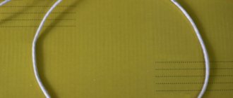
Coil for pulse metal detector made of twisted pair
From a twisted pair of wires it is possible to build a wonderful sensor, which is an indispensable component for a pulse device. Such a coil will have a search depth of more than one and a half meters. This design is distinguished by good sensitivity to various small-sized products, which include gold jewelry, small change, etc. In order to make such a coil, you need to first prepare a twisted pair wire, which can be purchased without any problems wherever radio devices are sold. The wire is made of four twisted pairs without a screen, it is very important that it be copper and not bimetallic
In order to make such a coil, you need to follow these instructions:
· Make a piece of wire, the length of which is 2.7 meters. · Mark exactly half of the section. After this, you should also measure 41 cm from each end. · According to the marks made, you need to make a ring from this wire and fix it using ordinary tape or adhesive tape. · The ends of the future coil should be slightly bent inward.
· Next comes a thorough stripping of the wire insulation, after which you will need to solder these wires in this order:
Assembly into one piece
First, the upper disk made of holey fiberglass was glued to the middle pancake made of 18 layers of fiberglass. This took literally a few milliliters of epoxy - this was enough to coat both surfaces to be glued over the entire area.
Ear mounting
I cut the grooves using a jigsaw. Naturally, I overdid it a little in one place:
To make the ears fit well, I made a small bevel on the edges of the cuts:
Now we had to decide which option is better? Ears can be placed in different ways...
Industrially produced reels are often made according to the right-hand version, but I prefer the left-handed one. In general, I often make leftist decisions...
In theory, the right method is better balanced, because The rod mount is closer to the center of gravity. But it is far from a fact that after lightening the coil, its center of gravity will not shift in one direction or another.
The left mounting method looks more visually pleasing (IMHO), and in this case the total length of the metal detector when folded will be a couple of centimeters shorter. For someone who plans to carry the device in a backpack, this may be important.
In general, I made my choice and started gluing. He generously smeared it with bauxite, securely fixed it in the desired position and left it to harden:
After hardening, I sanded off everything sticking out from the back side with sandpaper:
Cable entry
Then, using a round file, I prepared grooves for the conductors, inserted the connecting cable through the hole and glued it tightly:
To prevent strong kinks, the cable at the entry point needed to be somehow reinforced. For these purposes, I used this little rubber thing that I got from God knows where:
Of course, if I had a normal sealed lead-in, it would be much better, but... it will do.
All that remained was to glue the third pancake (the bottom).
Finishing the frame
To glue the third pancake it took several milliliters of bauxite and a couple of hours for everything to set. Here is the result: Thus, I received a rigid and durable frame, fully prepared for winding wire.
Winding sealing
An enameled copper wire with a diameter of 0.71 mm was used as a winding wire. After winding 27 turns, the sensor became heavier by another 65 grams:
Now the winding had to be caulked somehow. As putty I used a mixture of epoxy resin and finely chopped fiberglass (I learned about this super recipe from this article).
In short, I cut some fiberglass:
and mixed it thoroughly with bauxite with the addition of ballpoint pen paste. The result was a viscous substance similar to wet hair. With this composition you can cover any cracks without problems:
Pieces of fiberglass give the putty the necessary viscosity, and after hardening, provide increased strength to the adhesive joint.
So that the mixture is properly compacted, and the resin saturates the turns of the wire, I wrap it all with electrical tape tightly:
The electrical tape must be green or, at worst, blue.
After everything froze thoroughly, I wondered how strong the structure turned out to be. It turned out that the reel could easily support my weight (about 80 kg).
In fact, we don’t need such a heavy-duty reel; its weight is much more important. Too much mass of the sensor will definitely cause shoulder pain, especially if you plan to conduct a long search.
TEMPLATE FOR METAL DETECTOR SENSORS HOUSINGS
Much has already been said and written about vacuum molding of housings for metal detector sensors. It seems to be nothing complicated. A vacuum cleaner, an oven and a box made from improvised materials with many holes. The main question is where to get the template for the body. And so, when I felt the urge to make another sensor, I decided to write this article. So, let's begin. First of all, you need to make a drawing of the sensor in any graphics editor, I use Visio from Microsoft.
When the drawing is ready, we print it out and move to the manufacturing site. I make templates from 20 mm plywood. For my work, a small circular saw, a jigsaw and a drill are very useful to me.
First, glue the drawing onto the plywood and trim off all excess from the outside. Then, holes with the required radius must be drilled in all internal corners. Particular attention must be paid to the perpendicularity of the holes. Otherwise, difficulties may arise when extracting the template.
Next, using a jigsaw, we cut out all the excess from the inside.
Now that we already have a silhouette dear to our hearts in our hands,
We arm ourselves with sandpaper, all kinds of files and rasps, and patiently level out all the unevenness.
If possible, it is necessary to make a slight narrowing at the top, again to make it easier to remove the template from the finished product. Then, in the place where the pressure seal is attached, it is advisable to glue a boss. It will allow you to hide the sealed lead-in nut, and the latter will not interfere with the placement of the capacitors.
Next, using a circular saw, we make the ears. The distance between them was 24 mm, taking into account the thickness of the plastic.
Glue the ears to the template.
To better retract the plastic, it is advisable to make small through holes in the corners.
It took me less than three hours to make, not counting the preparation of the drawing. It remains to check it in action.
I mostly use white plastic for sensors. It heats up less in the sun, and accordingly the balance floats less. But that is another story. I wish you success. I hope that the article is useful to someone. Attached is a drawing of a butterfly in MSVisio and PDF. Best regards, Slavochny .
Forum for discussing the material TEMPLATE FOR METAL DETECTOR SENSORS CASES
AIMTEC AMSR and AMSRI switching voltage regulators are an excellent replacement for the popular 78xx / 79xx microcircuits. Code button for restricting access to objects, a simple circuit with a relay on the Attiny13 MK. High-compensation volume control with adaptation to the tone control - theory and practice.
Facilitating
To reduce the weight of the coil, it was decided to cut out some sections of the structure:
This manipulation allowed me to lose 168 grams of excess weight. At the same time, the strength of the sensor has practically not decreased, as can be seen in this video:
Now, with hindsight, I understand how the coil could have been made a little lighter. To do this, it was necessary to make large holes in the middle pancake in advance (before gluing everything together). Something like this:
The voids inside the structure would have almost no effect on the strength, but would reduce the total mass by another 20-30 grams. Now, of course, it’s too late to rush around, but I’ll keep it in mind for the future.
Another way to simplify the design of the sensor is to reduce the width of the outer ring (where the wire turns are laid) by 6-7 millimeters. Of course, this can be done now, but there is no such need yet.
Spontaneous signals
But there is another factor that can both darken the search and completely discourage the desire to engage in this hobby in general - this is an incorrectly wound coil cable. Here's the thing. On the one hand, and I already talked about this, if the cable is wound incorrectly, there is every chance that with an unsuccessful swing, when the coil cable catches a little on the grass, the wire will simply fly out of the socket.
Another option is possible, when a search engine identifies a find in a dump, puts its own next to it, and for convenience bends the reel. Moreover, if the cable is wound incorrectly, separation is inevitable. On the other hand, I have had cases when I already thought that my metal detector had gone crazy, since the spontaneous signals were tormented. As it turned out later, the whole point was that the cable was wound incorrectly.
Finish painting
I found an excellent paint for fiberglass and fiberglass products - epoxy resin with the addition of a dye of the desired color. Since the entire structure of my sensor is made on the basis of bauxite, the resin-based paint will have excellent adhesion and will fit like original.
I used alkyd enamel PF-115 as a black dye, adding it until the required hiding power was obtained.
As practice has shown, a layer of such paint holds very firmly, and looks as if the product was dipped in liquid plastic:
In this case, the color can be any depending on the enamel used.
The final weight of the search coil together with the cable after painting is 407 g
The cable separately weighs ~80 grams.
Examination
After our homemade metal detector coil was completely ready, we had to check it for internal breaks. The easiest way to check is to use a tester to measure the winding resistance, which normally should be very low (maximum 2.5 Ohms).
In my case, the resistance of the coil together with two meters of connecting cable turned out to be around 0.9 Ohm.
Unfortunately, this simple method will not be able to detect an interturn short circuit, so you have to rely on your accuracy when winding. A short circuit, if there is one, will immediately manifest itself after starting the circuit - the metal detector will consume increased current and have extremely low sensitivity.
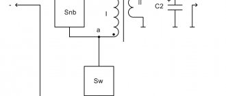
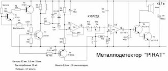
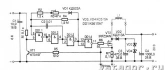
Pirate metal detector circuit
The pirate metal detector consists of transmitting and receiving units. The transmitting unit consists of a pulse generator which is assembled on the NE555 microcircuit and a powerful switch on the IRF740 transistor. The receiving unit consists of a K157UD2 microcircuit and a BC547 transistor.
In fact, the details are quite common, but if you still couldn’t find them, try using analogues. The NE555 timer can be replaced with a domestic analog KR1006VI1. Instead of the IRF740 transistor, you can install any bipolar NPN structure with an NEC of at least 200 volts, you can even remove it from an energy-saving lamp or phone charger; in extreme cases, even a KT817 will do. Transistors BC557 and BC547, for domestic KT3107 and KT3102. The K157UD2 operational amplifier has a complete analogue of the KR1434UD1V, it can also be replaced with an imported TL072, but in this case, you will need to redo the board pinout, since it has 8 legs. I also have a Pirate metal detector on TL072, the circuit diagram and board are in the general archive. By the way, the pulse generator can also be assembled using transistors: