DIY manual hydraulic pump
The hydraulic (manual) pump is quite in demand in the industrial sector. Its main task can be called pumping fuels and lubricants.
At the same time, the models have their own permissible viscosity standards. Additionally, the devices differ in their design. The main element of a hand pump can be called the dispenser pipe.
In some cases, telescopic intakes are used instead.
How is it built?
The standard manual (hydraulic) pump has a simple device. There is a test hose located at the bottom of the housing.
It is attached to the mechanism through a special hole using clamps. There is a valve higher up in the hand pump that controls the pressure.
By turning it clockwise, you can adjust the pumping force.
There is a plug for filling the tank. Below it is a small port, which is designed to connect to the general system. The mechanism also has a separate reservoir with a pipe for liquid.
The hydraulic cylinder is connected to the hand pump using a threaded method. To adjust the valve intensity, manufacturers install special regulators. With their help you can easily change the pressure.
In this case, the pump handle is installed separately, which is secured with a plug.
Diagram of a hand pump for pumping out oil
To pump out large quantities of oil, a durable hydraulic cylinder is required (a diagram of a manual hydraulic pump is shown below).
As a rule, it is reinforced with a small support. As a result, it is possible to secure it more tightly. Additionally, bolts are used for this.
Among other things, the hand pump is equipped with a hydraulic tube. Its main task is to supply pressure to the cylinder. For this purpose, a tee is installed in the device.
It is mounted on a special cushion, which is fixed on a washer. It is also secured with nuts. A rubber band is used for the holder in the hand pump.
In this case, the fitting is located at the very bottom.
Pump repair
In order to repair a hydraulic hand pump, you need to find out as much as possible about the breakdown. First of all, you should look at the pressure gauge readings.
If the pressure deviates from the norm, this is due to the central reservoir, the tightness of which may be compromised. In order to replace it, you will need a standard set of tools.
First of all, unscrew the upper bushing and disconnect the hydraulic pump handle. Next, you need to carefully remove the protective washer.
After this, it is possible to disconnect the plug. Directly below it is a reservoir. If external inspection does not show obvious deformation, the shut-off valve must be unscrewed from it.
After this, experts advise checking the functionality of the valve. If it is quite tight, you need to lubricate it. After this, the mechanism should be folded and checked for functionality.
The second common problem with pumps is considered to be abrasion of the rubber plug. In this case, you can simply replace it. In this case, it is necessary to find out its exact diameter and thickness. After completing the repair work, the entire mechanism also needs lubrication.
How are homemade models created?
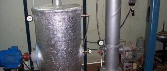
Today, homemade devices of this type are quite rare. However, you can make a hydraulic pump (manual) with your own hands. First of all, a steel tank is used as a body.
It requires a valve to control the pressure. It is secured at the top with a washer. A lever is used to adjust the shut-off valve. In this case, you can use a cast iron pipe.
To control the pressure, a pressure gauge should be installed.
You will need a sleeve with a pipe that will prevent the valve from twisting. As a result, you can fold a device that can withstand a pressure of no more than 4 atm.
Considering all of the above, such devices are considered ineffective and are rarely used in industry.
Hydraulic pumps NRG
HP pumps are reliable pressure sources. Moreover, they can be connected to various hydraulic systems. The manual hydraulic pump NRG-7007 has a nominal tank volume of 0.7 liters.
At the same time, its useful volume is 0.6 liters, and this modification can withstand a pressure of 1.3 MPa. Overall its performance is pretty good.
If we consider high-pressure pumps, then the NRG-7110 device deserves attention.
Its nominal tank volume is 1 liter. In this case, the maximum pressure is maintained at 2.7 MPa, and the force on the handle must be applied at 50 kgf. The dimensions of this modification are as follows: width - 310 mm, height - 320 mm, and length - 750 mm.
The hydraulic pump (manual) NGR-7016 has a nominal tank volume of 16 liters. At the same time, its useful volume is 14 liters. The pressure at the first stage is maintained at 2.7 MPa, and the system capacity is 113 cubic meters. see in one move.
This hydraulic (manual) pump weighs as much as 29 kg.
NRG pumps with distributors
Hand pumps of the NRG series are produced in some cases with distributors. These models have the letter “P” in their names, so anyone can recognize them.
A distinctive feature of these devices is considered to be high maximum pressure. Moreover, their tanks are installed in a variety of diameters.
If we consider the modification NRG-7020R, then the useful volume of the chamber is exactly 2 liters, and the pressure is maintained at around 3 MPa.
The productivity of the device at the second stage is 113 cubic meters. see the move. In this case, the force on the handle should be applied at 55 kgf. This hydraulic (manual) pump weighs 22 kg.
If we consider the NRG-67016R model, then its nominal tank volume is 14 liters, the “maximum” pressure is maintained at 4 MPa. The capacity of the mechanism at the second stage is 115 cubic meters. cm per move.
The assembled device weighs exactly 30 kg.
Single acting system
To connect a manual hydraulic pump to a single-acting system, you will need a special adapter. It is usually let in with a pressure gauge.
The most common modification of the adapter is considered to be the “MA100” model. Additionally, you will need a hose at least three meters long. Its end must connect to the coupling half.
The system must also have an actuator.
A distinctive feature of these devices is a powerful valve that can withstand heavy loads. It is connected to the system, as a rule, through a regular adapter.
Additionally, a BRS class half-coupling is used. To work, you will also need an adapter that will be attached to the tap.
Via an adapter, the pump can be connected to the actuator.
Double acting hydraulic system
A double-acting hydraulic system requires a standard adapter as well as a pump. In this case, the coupling half is used from the BRR series. It should also be noted that the rod can be connected to the system, and this is done to return the stroke.
By default, it is assumed that there is one hydraulic pipe, but several can be connected. In order to connect the pump to the actuator, a special hydraulic lock is used. It is installed on two connectors at once.
In this case, the pressure can jump to 3 MPa.
In this case, you should constantly monitor the pressure gauge readings. After installing the hydraulic lock, you need to tighten all the bolts and check the rod for functionality.
Additionally, it should be noted that protective bushings in this system can only be used of the UGZ class.
This is due to the fact that it is necessary to connect to the actuator with exactly two connectors.
How do hand pumps operate from a station?
The hand pump can only be connected to the station using an adapter of the ШП series. In this case, the standard connection diagram provides for the presence of a drain pipe. It is produced with the “T” marking.
Principle of operation
Hydraulic presses equipped with an electric drive are capable of developing enormous forces, which is explained by the design features of such equipment. The principle by which the electro-hydraulic press works is as follows.
- An electrically powered motor drives a hydraulic pump.
- The hydraulic pump, in turn, maintains the pressure of the working fluid in the first chamber of the press.
- The piston of the first chamber transmits pressure to the second cylinder of the electro-hydraulic press, where it increases significantly.
- The pressure created in the second chamber of the hydraulic cylinder is transmitted directly to the working body of the electrohydraulic press.
Diagram of a frame-type hydraulic press (click to enlarge)
Thus, the amount of working pressure that will be imparted to the working body of an electro-hydraulic press depends on how different the areas of the pistons in its two cylinders are.
The operation of the press, the main working body of which is a hydraulic pump, is based on Pascal's law, which states that the force acting on any area is transmitted throughout the entire volume, and it has equal value in all directions.
Types and scope of application
Both home-made and mass-produced hydraulic presses are classified according to several parameters:
- sizes;
- maximum force produced;
- design features of the equipment (in particular, the height of the rod).
The most powerful are hydraulic presses related to floor-type equipment.
A hydraulic floor-type press, distinguished by significant dimensions, is capable of creating pressure at one point, the value of which can reach tens of megapascals. The scope of use of equipment of this type, which can be equipped with additional devices, is quite wide. Floor hydraulic presses are necessary to solve such technical problems as:
- installation and removal of bushings, shafts, bearings;
- pipe bending;
- pressing of products made from various materials, including metal.
Some models of floor-type electro-hydraulic presses provide the ability to change the height of the work table.
Electro-hydraulic press 2135-1M, force 40 tons
Tabletop hydraulic presses, along with their small size, are characterized by less power.
The pressure created by such equipment installed on a desktop or workbench rarely reaches 20 tons.
The compactness of tabletop electro-hydraulic presses allows them to be used in small automotive and home workshops.
An important parameter of electrohydraulic presses, in addition to the force they are capable of creating, is the height of their rod.
This parameter, in particular, determines what size parts the equipment can work with.
If for tabletop presses this parameter can reach 100 mm, then for floor-standing models it reaches half a meter.
Due to their versatility, electrohydraulic presses are used in many fields of activity.
Such areas of activity, in particular, are mechanical engineering, woodworking and food industries.
However, most often such equipment can be found at vehicle repair stations.
Using it, you can successfully solve not only all of the above technical problems, but also straighten dents and other damage to the car body.
Unlike pneumatic equipment, the use of which requires a rather complex pneumatic system, a hydraulic press with an electric drive can simply be connected to an electrical power supply, and it will function normally.
How to make your own hydraulic press with electric drive
Serial hydraulic presses with electric drive are quite expensive, so it makes sense to think about how to make an electro-hydraulic press with your own hands. To do this you will need the following tools and equipment:
- welding machine;
- lathe;
- drilling machine;
- Bulgarian;
- electric drill.
This press will be able to produce a maximum pressure of 35 tons
The supporting structure of the electro-hydraulic press, which is subjected to the main mechanical loads, is the frame, the strength of which should be given special attention.
A T-beam made of metal of such thickness that it can withstand the loads created by a hydraulic press without bending is well suited for these purposes.
Press frame made of I-beam
Structurally, the frame of a homemade electro-hydraulic press is a U-shaped frame, welded from T-beams and installed on a base, for the manufacture of which thinner channels and angles can be used. In the middle part of such a frame (along its height), a working platform is welded into it, for the manufacture of which thick-walled channels are used.
In order for such fastening to be as reliable as possible, it is better to fix the hydraulic pump on a 20 mm metal plate using a flange.
The metal plate itself, which will absorb all mechanical forces, is mounted on two T-beams.
The rigidity of the structure is ensured by high-quality welding seams
Installation of the hydraulic cylinder on the bed
The process of installing a hydraulic cylinder on the frame of a homemade hydraulic press is carried out in a certain sequence.
1. Adjustment of hydraulic cylinder, flange and plate
The body of the hydraulic cylinder, so that it can be placed in the inner part of the flange, is turned on a lathe.
The flange, which can be made from a car hub, is also processed on a lathe.
20 mm thick plate with a welded boss in the center
After the hole in the slab is bored out, it is welded to the beams of the base frame.
The flange, in which the mounting hole has already been prepared, is put on the hydraulic cylinder and welded in a circle.
Flange welded to hydraulic cylinder
It is very important that the flange and hydraulic cylinder are connected as smoothly as possible; for this, the adjacent surface of the flange must be machined on a lathe. 2. Installation of upper beams and hydraulic cylinder
The plate, which is already connected to the beams, is installed on the frame and connected to it by welding.
Through the holes on the mounting part of the flange, holes are drilled in the plate, which are necessary for placing the mounting bolts.
The installation of the upper beam is carried out strictly perpendicular to the supports
The hydraulic cylinder should not be attached to only one point, so it is necessary to make another flange, put it on the top of the cylinder and weld it to the beams.
Installing the Top Flange
T-beams installed in the upper part of the frame are connected to each other by welding.
3. Installation of the frame and oil station
In order for the hydraulic press you have made to fully function, you need to install an oil station on it and connect it with a hydraulic cylinder using hoses.
Installation of a frame and a two-flow hydraulic station delivering a pressure of 700 bar
Thus, it is not difficult to make a hydraulic press with an electric drive with your own hands. At the same time, you will have at your disposal equipment that can solve many technical problems.
Hydraulic pump: price, device, types
The high pressure hydraulic pump is very widely used in everyday life and industry.
It is especially popular in mechanical engineering, the oil and gas industry and construction, where without it it is impossible to carry out a huge amount of work.
At the same time, the hydraulic pump itself cannot be called a very complex mechanism.
Device and types
Hydraulic equipment always works by moving fluids from one piston to another. In this way, it is possible to convert hydraulic energy into mechanical energy.
The design of a hydraulic pump largely depends on its type. However, many elements in it are similar and work on the same principle.
Special oil in the pump housing is pumped through a specific system.
The resulting energy affects the device to which the pump is connected.
Oil can be pumped in different ways. In mechanical engineering, rotating shafts are used, but in everyday life, electric motors and even manual drives are used. Most pumps can only operate in one direction.
It is very important to understand that different types of hydraulic pumps differ significantly in their design and operating principle. Therefore, all samples can be judged and evaluated only after they have been fully examined.
How are homemade models created?
Today, homemade devices of this type are quite rare. However, you can make a hydraulic pump (manual) with your own hands. First of all, a steel tank is used as a body. It requires a valve to control the pressure. It is secured at the top with a washer. A lever is used to adjust the shut-off valve. In this case, you can use a cast iron pipe. To control the pressure, a pressure gauge should be installed.
You will need a sleeve with a pipe that will prevent the valve from twisting. As a result, you can fold a device that can withstand a pressure of no more than 4 atm. A distinctive feature of homemade hand pumps is their large dimensions. And to bring the lever into operation, great efforts must be made. Considering all of the above, such devices are considered ineffective and are rarely used in industry.
DIY manual hydraulic pump
The hydraulic (manual) pump is quite in demand in the industrial sector. Its main task can be called pumping fuels and lubricants.
At the same time, the models have their own permissible viscosity standards. Additionally, the devices differ in their design. The main element of a hand pump can be called the dispenser pipe.
In some cases, telescopic intakes are used instead.
Design of pumps with half-coupling
A feature of pumps with a half-coupling is considered to be volumetric cylinders. At the same time, they are attached to the camera using special clamps that are fixed with bolts. Additionally, there is a protective washer that locks the central rod. Directly below this is a small tee that connects to the hand pump sleeve.
How is it built?
The standard manual (hydraulic) pump has a simple device. There is a test hose located at the bottom of the housing. It is attached to the mechanism through a special hole using clamps. There is a valve higher up in the hand pump that controls the pressure. By turning it clockwise, you can adjust the pumping force.
There is a plug for filling the tank. Below it is a small port, which is designed to connect to the general system. The mechanism also has a separate reservoir with a pipe for liquid. The hydraulic cylinder is connected to the hand pump using a threaded method. To adjust the valve intensity, manufacturers install special regulators. With their help you can easily change the pressure. In this case, the pump handle is installed separately, which is secured with a plug.
The design of a manual hydraulic pump and its operating principle
The simplest to set up and operate is a manual hydraulic pump. It is based on the principle of fluid displacement. In industry, such units are quite in demand; their main function is pumping fuels and lubricants.
Hydraulic hand pump
Design and diagram of a manual hydraulic pump
Diagram of a hydraulic hand pump
The manual hydraulic pump consists of two main parts, the pumping unit (1) and the hydraulic tank (2). They are connected to each other by a pin (3). You need to fill the liquid through the hole, having first unscrewed the plug that closes it (4).
The handle (6) with the lever (7) drives the plunger (8) of the first and second stages, made as one part. The pumping unit has a two-stage structure. Stage number one, with reduced pressure and higher productivity, serves to accelerate the movement of the hydraulic cylinder plunger.
Stage number two, at high pressure and lower capacity, serves to obtain the operating force of the actuator. Overload protection is provided by a safety valve (9).
Pressure is released and hydraulic fluid is extracted from the cylinder cavity into the tank using a screw (10).
Working principle of a manual hydraulic pump
Before starting to work with any pump, be sure to inspect the tool and if cracks and chips are found on the surface, do not use it. It is important to check whether the high pressure hose is tightly connected to the hand pump.
Work algorithm:
- We connect the pump to the hydraulic system with a quick-release coupling;
- Turn the valve all the way clockwise.
- Using progressive movements, pump the pump handle up and down. As a result, oil is pumped into the system from the pump. At the same time, pressure builds up in the system, and the piston of the hydraulic tool moves, into which we pump oil.
- In a situation where the working piston of the system into which oil is poured reaches its final position, increased pressure will be created in the system, as a result it will be impossible to pump oil. Then it is necessary to stop the pump to avoid failure of the device.
- In order to lower the pressure in the system, you need to slowly turn the valve all the way counterclockwise. As a result, oil from the system will flow back into the pump. This occurs due to the return of the piston to its original position.
- After finishing pumping oil, you should inspect the hydraulic system for oil leaks, and you should also inspect the pump. If leaks are found, they should be corrected immediately.
Malfunctions and their elimination
- The manual hydraulic pump does not supply pressure. The main reasons for this behavior may be the lack of hydraulic fluid in the tank or the drain valve is not closed. In any case, it is worth checking these versions; if the tap is still closed and there is liquid, then perhaps the reason is that the suction or discharge valve is clogged. Then you will have to disassemble and wash the hydraulic pump valves.
- Oil (hydraulic fluid) is leaking in the gap located between the body and the plunger. In this case, it is highly likely that the O-rings are worn out or damaged. It is recommended to replace them immediately to prevent failure.
- Does not produce the performance specified in the data sheet. Most likely the filter element of the manual hydraulic pump is clogged. It is recommended to thoroughly rinse the filter element.
- Does not develop the pressure specified in the technical data sheet. The safety valve is not adjusted correctly. You need to set the safety valve to the pressure indicated in the data sheet.
How to choose the right hydraulic manual pump?
Three main selection factors:
1. The hydraulic pump tank must be larger than the hydraulic cylinder capacity.
2. Manual hydraulic pumps come in two types: single-acting and double-acting, pay attention to this parameter.
3. The pressure level should match what you need for work. Select a hydraulic pump with a pressure equal to or greater than the maximum pressure of the hydraulic cylinder.
Is it worth making a manual hydraulic pump yourself?
At the moment, hand-made pumps are almost never found. Despite this, you can make a hydraulic pump with your own hands. We will need a steel tank. The body will be made from it. To control the pressure in the tank you need a valve. It needs to be secured at the top with a washer.
A lever is installed to control the closing valve. A cast iron pipe may be suitable. Use a pressure gauge to monitor pressure. In the end, you will end up with a device that will not withstand pressure of more than 4 atmospheres.
With all this, a homemade hydraulic pump will take up a lot of space and be inconvenient to carry. The disadvantage of homemade hand pumps is their low efficiency; quite a lot of force will be required to activate the pump. Also, homemade devices are very unreliable.
And if you take into account all the disadvantages, then spending resources on creating a homemade manual hydraulic pump is very ineffective. That is why they are not common.
Manual hydraulic pumps NRG
NRG hydraulic pumps are very reliable devices and are very common here in Russia as they are produced here. The NRG line of pumps contains devices with distributors.
The letter “P” is usually placed at the end of the designation of such instruments. This letter means that the tool can work with double-acting hydraulic devices.
Let's consider several models of NRG manual hydraulic pumps:
- Model nrg-7020R. Creates a maximum pressure of 700 bar. And it has a nominal tank volume of 2 liters. The kit includes a hydraulic distributor that allows you to work with both single- and double-acting devices.
- Model nrg-7007. Also creates a pressure of 700 bar. The nominal tank volume is 0.7 liters. The advantages of this model are the presence of a safety valve, minimal force on the handle, and two stages of oil supply. This tool is designed for single-acting hydraulic tools with a spring return rod.
- Model nrg-67016R. The nominal tank volume is 14 liters. Handle force 55 kg. Pressure maximum 4 MPa. Capacity is 115 cubic cm. Such a device weighs as much as 30 kg and is quite large. Suitable for a small car service.
Summary, pros and cons of hydraulic hand pumps
Pros:
- Easy to use;
- Do not require any additional energy source;
- High maintainability;
- Have high mobility;
Minuses:
- Low performance;
- Muscular strength of the operator is needed, therefore, additional load on the operator;
Bottom line, it is reasonable to use a manual hydraulic pump in small workshops and mobile services, where there is no need to pump in large volumes of oil and build up significant pressure. In general, hand pumps are very convenient, and most importantly, they are mobile since they do not depend on any energy sources.
The design of a manual hydraulic pump and its operating principle Link to the main publication
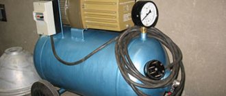
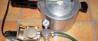
Diagram of the device from the electric petrol drive
In this case, a jack or a puller can act as an actuator. In this case, the station is attached directly to the pump. For this purpose, only rubber clamps are used, which provide high grip. The pressure gauge is installed as standard near the actuator.
The tap should be mentioned. For a hand pump to work properly, it must be a two-way pump. In this case, the air tank will withstand any load. The safety valve in this system is mounted immediately above the high pressure hose.
Do-it-yourself manual high-pressure hydraulic pump
High-pressure hydraulic pumps operating at characteristics of 42-70 MPa or more are widely used to drive small-sized hand tools, special equipment, and are used in test benches and other critical products.
When transmitting the same power from the prime mover to the actuator hydraulic mechanism, an increase in pressure entails a decrease in flow.
As a result, smaller pump sizes, hydraulic motors, valves, piping and other components are required.
Classification
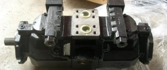
Extensive experience in the creation and operation of various hydraulic drives has shown that only limited types of pumps can develop high pressure. These include piston and plunger types. The hydraulic pump drive comes in three design types:
- manual (muscular);
- mechanical;
- pneumatic.
The use of hydraulic drives with ultra-high pressure (over 70 MPa) makes it possible to significantly reduce the dimensions and weight of equipment and increase its specific performance. The development of high-pressure systems is one of the key factors in the creation of compact, powerful hydraulic drives and mini-equipment for various sectors of the economy.
Muscle driven pumps
A manual (lever) hydraulic pump is driven by human muscle power. Its main component is a piston, which moves inside the cylinder.
The movement of the piston is controlled by a lever. The lever is moved by a person's hand or a foot pedal with a return spring.
The principle of its operation is based on the suction and injection of working fluid during the reciprocating movement of the piston.
Design
Let's look at how a hydraulic pump for a muscle-driven press is designed. A piston is installed in the cylindrical cavity of the pump housing, rigidly connected to the rod. The rod is pivotally connected to the drive lever. An intermediate valve is installed in the piston, connecting the piston and rod cavities of the pump.
The piston cavity is connected to the hydraulic tank through the inlet valve. In such pumps, the hydraulic tank is usually an integral part of their design. A suction filter is often installed in the tank in front of the inlet valve.
The rod cavity is connected through the outlet valve to the outlet port of the pump. Special seals are installed in the pump housing cover, which also serves as a rod guide.
A screw valve located in the bypass channel of the pump serves to return the working fluid to the hydraulic tank. A plug is provided in the housing for oil changes and maintenance.
Characteristics
The working volume of such pumps is small, the drive lever has a relatively short stroke, so the generated flow rate is low.
However, these are the most common units around the world, as they are used in so many industrial areas. The pressure developed by manual systems reaches 70-280 MPa.
Due to the simplicity of the design, repairing manual hydraulic pumps does not cause any difficulties.
Two-stage hand pumps
Their scheme is more complex. They contain two pistons, which are pivotally connected to the rocker arm of the drive arm. When the drive lever is moved to the left, one piston rises and sucks in fluid, and the second one lowers and pumps it into the hydraulic system.
When the drive lever is moved to the right, on the contrary, the first piston pumps liquid, and the second sucks it in. Thus, when identical pistons operate alternately, the working fluid is supplied continuously and more evenly than in single-stage models.
A two-stage hydraulic hand pump is capable of driving two hydraulic system circuits simultaneously. Two-stage versions of hand pumps with coaxial pistons of various sizes are widely used in industry.
At low pressure, both pistons pump out working fluid at a high flow rate. At high loads, only one piston with a small area pumps liquid into the circuit, developing high pressure at low flow rate.
Muscular drive models are used in various mechanisms:
- press;
- jacks;
- static hydraulic tools;
- lifting platforms;
- small-sized cranes;
- in laboratory testing equipment for pressures up to 200 MPa.
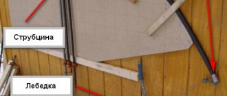
Self-made hydraulic pump for the press
It is not difficult to assemble such a system yourself. First, a metal frame with a height of approximately human height is welded (you can use ordinary channels). Holes are drilled (burned) on the sides of the vertical posts at a certain distance from each other.
Metal rods (reinforcement) will be inserted into them, which act as a support for the platform on which components that require the use of great force are installed. For example, when pressing/pressing bearings, bushings, etc.
A series of vertical holes allows you to adjust the height relative to the press.
Gear
Rotary hydraulic machines of this type have found application in lubrication systems, road and agricultural special equipment, and mobile hydraulic structures. Their advantages include:
- simplicity of design;
- operation at frequencies up to 5000 rpm;
- light weight;
- compactness.
Notable disadvantages:
- working pressure up to 20 MPa;
- low efficiency;
- small resource;
- pulsation problems.
The working displacing elements of the structure are two gears. They differ in the type of engagement:
- External. From the inlet side, the gears rotate in different directions, capture the liquid in the cavities of the teeth and move it along the walls of the housing to the outlet of the pump. When the teeth engage, the working fluid is pushed out of the recesses towards the exit of the housing.
- Internal. The operating principle does not change. The fluid is transferred to the discharge area in the cavities between the gear teeth along the surface of the auxiliary crescent-shaped separator. Pressure pulsation and noise levels in such units are reduced.