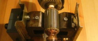
It's been about a year and a half since I started doing electronics repairs regularly. As it turned out, this matter is no less interesting than the design of electronic structures. Little by little people appeared who wanted, some from time to time and some regularly, to collaborate with me as a master. Due to the fact that the profitability of most of the repairs carried out does not allow renting premises, otherwise rent eats up most of the profit, I work mainly at home or go with tools to familiar individual entrepreneurs who buy consumer electronics and have a workshop.
In parallel with a friend, we buy equipment on the local forum and Avito, repair it and the friend sells it, both in shares of the sale. But that's not the point. Today I decided to share with readers a diagram of a simple, but very useful for any electronics repairman, ESR meter, which allows you to correctly measure this parameter, in most cases, without soldering the electrolytic capacitors. ESR, also known as ESR (Equivalent Series Resistance) is a capacitor parameter that greatly influences its performance when operating in high-frequency circuits. What kind of devices are these?
These are absolutely any circuits using stabilizers, DC-DC power converters, switching power supplies for any equipment, from computers to mobile chargers.
Swollen capacitor
Without this device, a significant part of the repairs I performed either could not have been performed at all, or was still performed, but with great inconvenience in the form of constant soldering and soldering back electrolytic capacitors of small value, in order to measure the equivalent series resistance using a transistor tester. My device allows you to measure this parameter without desoldering the part, simply by touching the terminals of the capacitor with tweezers.
These capacitors with a nominal value of 0.33-22 uF, as is known, very rarely have notches in the upper part of the case, along which capacitors of a higher nominal value swell and open like a rose, for example, the familiar capacitors on motherboards and power supplies. The fact is that a capacitor that does not have these notches to release the excess pressure generated is visually, without measuring with a device, even for an experienced electronics engineer, in no way distinguishable from a fully working one.
Computer power supply
Of course, if a home craftsman needs a one-time repair, for example, an ATX computer power supply, there is no point in assembling this device; it is easier to immediately replace all the small capacitors with new ones, but if you repair at least five power supplies every six months, this device is already desirable for you assembly. What alternatives are there to assembling this meter? A purchased device that costs about 2000 rubles, ESR micro.
ESR micro – photo
Of the differences and advantages of a purchased device, I can only name that its readings are displayed immediately in milliOhms, while my device needs to be converted from milliVolts to milliOhms. Which, however, does not cause any difficulties, it is enough to calibrate the device using the values of low-resistance precision resistors and create a table for yourself. After working with the device for a couple of months, visually, without any tables, just by looking at the display of the multimeter you can already see the normal value of the ESR of the capacitor - on the verge or replacement is already necessary. The diagram of my device, by the way, was once taken from Radio magazine.
What is a capacitor
A capacitor is an electrical element that is capable of storing a certain electrical charge. The main parameter of the element is the capacitance, which is calculated in farads. 1 farad is quite a large value. Modern capacitors have the following capacitance designations:
- picofarad is denoted pF or pF;
- nanofarad is denoted nF or nF;
- microfarad is denoted mF or mF.
The principle of operation of the device is quite simple. The operation and delivery of a pulse differs only from the current in the circuit to which it is connected.
AC circuit
In an AC circuit, a capacitor is a resistance. It quickly accumulates a certain charge and gradually releases it. Accumulation and full release occurs during a change in the electric wave.
DC circuit
In a DC circuit, charge accumulates on the plates, increasing the potential difference across the plates. The potential difference increases to the voltage value. As soon as it becomes equal to the voltage, the common circuit is broken.
Calculation using formulas
Calculation of the nominal capacity of an element is required in 2 cases:
- Electronic equipment designers calculate the parameter when creating circuits.
- In the absence of capacitors of suitable power and capacity, craftsmen use element calculations to select from available parts.
RC circuits are calculated using the value of impedance - complex resistance (Z). Ra - current losses due to heating of circuit participants. Ri and Re — take into account the influence of inductance and capacitance of the elements. At the resistor terminals in the RC circuit, the voltage Uр is inversely proportional to Z.
Thermal resistance increases the potential across the load, and reactive resistance decreases. Operating a capacitor at frequencies above resonant frequencies, when the reactive component of the complex resistance increases, leads to voltage losses.
The resonance frequency is inversely proportional to the ability to accumulate charge. From the formula for determining Fр, they calculate what values of C (capacitor capacitance) are required for the operation of the circuit.
To calculate pulse circuits, the circuit time constant is used, which determines the effect of RC on the pulse structure. If the circuit resistance and capacitor charging time are known, the capacitance is calculated using the time constant formula. The truth of the result is influenced by the human factor.
Craftsmen use parallel and series connections of capacitors. The calculation formulas are the reverse of the formulas for resistors.
A series connection makes the capacitance smaller in the connection of elements; a parallel circuit adds up the values.
Types of capacitors
There are several types and types of capacitors. They are divided among themselves according to the following principle:
- Changing capacity. This change classifies electronic elements into constant, variable and interlinear.
- The dielectric material can be air, mica, Teflon, polycarbonate, or electrolyte.
- Installation. Based on the installation method, these radio components are divided into mounted and printed.
There are several types of capacitive devices, divided according to the principle of construction and performance:
- Ceramic. These elements are made of a disk with a conductor on both sides. Such printed parts have low operating voltage but high capacity.
- Film. Such capacitors have a film rolled into a roll inside the housing. A large charge and high operating voltage can be placed across all layers. The layers are made of foil with a dielectric on one side.
- Electrolytic. These devices are similar in structure to film devices. The difference is the dielectric material. For these printed elements, the dielectric is paper impregnated with electrolyte.
- Variables. These are devices for precise adjustment of instruments. The capacitance is changed mechanically.
- Interlinear. These are elements of one-time setting of parameters in devices. Such settings are performed only at manufacturing plants.
- Launchers. These capacitors are used to start electric motors. They operate on an alternating current circuit of 220 volts.
How to use the device correctly
If the nominal voltage is unknown, then you can act on the basis that it is 10-12 V. Typically, resistors with a resistance of 5-10 KOhm are used.
To check a part without removing it from the circuit, you can connect a capacitor with the same parameters in working condition in parallel with it. If the circuit restores its operation, this means that the part was faulty and should be replaced.
Bridge circuit
Measuring capacitance without desoldering the board is difficult and only accessible to a professional specialist. A device for testing electrolytic capacitors without desoldering can only be used taking into account the connection diagram of the capacitor. The fact is that the result obtained will significantly depend on the method of connecting the part and in various situations may show results that are difficult to explain. For example, if a coil is connected in parallel with it, then when measuring capacitance without soldering, zero resistance will be shown.
You may be interested in this Rating of the best soldering stations
If the capacitor is faulty, you need to check it using one of the available methods. In the event of a malfunction, it will need to be replaced in order for the board to restore its functionality.
Electrical circuits, consisting of conductors and semiconductors, include elements that allow them to accumulate charges and release them at the right moment. Because of this feature, such elements were initially called containers. The name comes from the times when electricity was considered a liquid and its storage device was considered a vessel. This not entirely successful definition is still used today, although the element itself is called a capacitor.
Types of capacitors and their appearance
Defining parameters
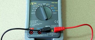
It’s very easy to check the element’s functionality yourself. Modern multimeters and testers have a corresponding function for this. The main parameter during testing will be the compliance of the declared and actual capacity, as well as the throughput of the radio component. The test can be carried out both on the board itself and by removing the part from the printed circuit board.
Capacity check
Often capacitors, especially old ones, have unclear capacitance markings on their housings. In order to find out the capacity of the working device, you need to use a multimeter that has a capacity measurement function. Modern multimeters have a measuring range from 20 nF to 200 mF. To determine the capacitance of an unmarked capacitor, you will have to test it in 5 modes: 20 nF, 200 nF, 2 mF, 20 mF, 200 mF. You will also have to take polarity into account if the element is polar. Before measurement, it is necessary to remove the capacitor from the circuit.
- The device switches to capacity test mode. Be sure to switch the probes to the cX socket.
- The element under test must be discharged before testing. This is done by shorting both ends.
- Both probes are connected to the terminals.
Measuring circuit
To determine the capacitance of an unknown capacitor, you should include it in a circuit consisting of a resistor and a power source. The input voltage is selected slightly lower than the rated voltage of the capacitor; if it is unknown, 10–12 volts will be sufficient. You also need a stopwatch. To eliminate the influence of the internal resistance of the power source on the circuit parameters, a switch must be installed at the input.
The resistance is selected experimentally, more for the convenience of timing, in most cases within five to ten kiloohms. The voltage across the capacitor is monitored with a voltmeter. Time is counted from the moment the power is turned on - when charging and turning off, if the discharge is controlled. Having known resistance and time values, the capacitance is calculated using the formula t = RC.
It is more convenient to count the discharge time of the capacitor and mark the values at 90% or 95% of the initial voltage; in this case, the calculation is carried out using the formulas 2.2t = 2.2RC and 3t = 3RC. In this way, you can find out the capacitance of electrolytic capacitors with an accuracy determined by the measurement errors of time, voltage and resistance. Using it for ceramic and other small capacitances, using a 50 Hz transformer and calculating capacitance, gives an unpredictable error.
Checking with a multimeter
To determine polarity using a multimeter, you must:
- Completely discharge the part by short-circuiting its leads.
- Connect the resistor to the “+” terminal of the multimeter.
- Connect the second end of the resistor to the terminal of the 12 volt power supply.
- Connect the resistor to the terminal of the capacitor.
- Connect the negative wire of the power supply to the 2nd terminal of the capacitor.
If the multimeter does not show the presence of current in the circuit, then the polarity of the element is correct. The “+” wire of the power supply was correctly connected to the “+” of the capacitor. If the multimeter shows the presence of current, then the polarity was not observed in the circuit.
Application of formulas
What should you do if you don’t have a multimeter with measurement sockets at hand, but only an ordinary household appliance? In this case, it is necessary to remember the laws of physics that will help determine the capacity.
To begin with, let us remember that in the case when a capacitor is charged from a source of constant voltage through a resistor, then there is a pattern according to which the voltage on the device will approach the voltage of the source and will ultimately become equal to it.
But in order not to expect this, you can simplify the process. For example, in a certain time, which is equal to 3*RC, during charging the element reaches 95% of the voltage applied to the RC circuit. Thus, the time constant can be determined from current and voltage. But more correctly, if you know the voltage in the power supply, the value of the resistor itself, the time constant is determined, and then the capacitance of the device.
For example, there is an electrolytic capacitor, the capacity of which can be found out by the marking, where 6800 uF 50V is written. But what if the device has been lying idle for a long time, and it is difficult to determine its working condition from the inscription? In this case, it is better to check its capacity to know for sure.
To do this you need to do the following:
- Using a multimeter, measure the resistance of the 10 kOhm resistor. For example, it turned out to be 9880 Ohms.
- We connect the power supply. We switch the multimeter to DC voltage measurement mode. Then we connect it to the power supply (via its terminals). After this, 12 volts is installed in the block (the number 12.00 V should appear on the multimeter). If it was not possible to adjust the voltage in the power supply, then we write down the results that were obtained.
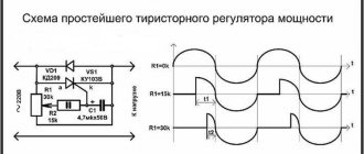
- Using a capacitor and a resistor we assemble an RC electrical circuit. The diagram below shows a simple RC circuit:
- Short-circuit the capacitor and connect the circuit to power. Using the device, once again determine the voltage supplied to the circuit and write down this value.
- Then you need to calculate 95% of the obtained value. For example, if it is 12 Volts, then it will be 11.4 V. That is, over a certain time, which is equal to 3 * RC, the capacitor will receive a voltage of 11.4 V. The formula is as follows:
- It remains to determine the time. To do this, we open up the device and use a stopwatch to count down. The definition of 3*RC will be calculated in this way: as soon as the voltage on the device is 11.4 V, this will mean the required time.
- Let's make a determination. To do this, divide the resulting time (in seconds) by the resistance in the resistor and by three. For example, it turned out to be 210 seconds. We divide this figure by 9880 and 3. The resulting value is 0.007085. This value is indicated in farads, or 7085 microfarads. The permissible deviation can be no more than 20%. If we take into account that the product indicates 6800 microfarads, our calculations are confirmed and fall within the standard.
How to determine the capacitance of a ceramic capacitor? In this case, you can make a determination using a network transformer. To do this, we connect the RC circuit to the secondary winding of the transformer, and it is connected to the network. Next, using a multimeter, measure the voltage on the capacitor and resistor. After this, it is necessary to make calculations: the current that passes through the resistor is calculated, then its voltage is divided by the resistance. The resulting capacitive reactance is Xc.
If there is a current frequency and Xc, you can determine the capacitance using the formula:
Checking the health of capacitors
Modern multimeters are capable of measuring and checking the performance of any radio components. But this device is not always at hand. You can check the capacitor using a tester.
Multimeter
If the multimeter has a special function for measuring capacitance, then it can be used to test any type of device. Ceramic, electrolytic, and starting radio components have the same operating principle, which means that serviceability checks can be carried out in the same way.
- Unsolder the part under test from the board and discharge it by closing the contacts.
- Set the multimeter to the “cX” capacitance detection mode.
- Switch the device to determine the maximum capacity range.
- Connect the probes to the legs or terminals of the capacitor.
- The multimeter will show the capacitance value. If one or more “0”s are displayed before the value, the device switches to a lower parameter.
Polarized capacitors (if the polarity is correct) show gradually increasing values from “0” to “1”. If the display shows “1” without changes, then the capacitor is not working. If the readings are “0”, then the element is closed internally.
Non-polar capacitors are checked by setting the multimeter to 2 MΩ. If the readings are higher than this value, then the device is working properly. Values less than 2 MΩ indicate a malfunction.
Tester
You can check the capacitor using a tester only to determine its general serviceability. Capacitance loss or voltage variation cannot be determined.
- To check, you need to set the tester to resistance mode.
- Unsolder and discharge the element being tested.
- If the radio component is polar, you need to connect the tester terminals to the terminals according to the polarity.
- Polar capacitors (having a large capacity) will charge for a few seconds, non-polar ones will show their value immediately.
Electric capacitance and its unit of measurement
The property of conducting bodies to accumulate and retain electric charge, measured by the ratio of the charge of a solitary conductor to its potential, is called electrical capacitance, or simply capacitance, and is denoted by the letter C.
The given formula for electrical capacitance allows you to set the unit of electrical capacitance.
In practice, charge is measured in coulombs, potential in volts, and capacitance in farads:
A conductor has a capacity of 1 farad and is given a charge of 1 coulomb, and the potential of the conductor increases by 1 volt.
The unit of measurement for electrical capacitance, the farad (denoted f or F), is very large. Therefore, smaller units are often used - the microfarad (μF or μF), which is a millionth of a farad:
1 µF = 10-6f,
and picofarad (pf), which is a millionth of a microfarad:
1 pf = 10-6 microfarads = 10-12 f.
Let's find the expression for the practical unit - farads in absolute units:
Testing without soldering
Testing the capacitor directly on the printed circuit board is very problematic. First, the faulty electrical appliance must be completely de-energized. It is also necessary to achieve the discharge of all capacitive elements in the circuit. Testing without soldering can show the resistance values of elements soldered nearby. But the check can still be carried out using a tweezer indicator.
First way
The first method is the simplest. The subject is checked by a tester and called with a multimeter. The device is put into resistance testing mode. It is also worth considering polarity. The multimeter probes are connected to the terminals of the capacitor and the resistance is measured. It is worth considering that the obtained value has no practical use, since it may be an indication of another element. In this way, you can check the capacitive part for a short circuit. If the values on the display begin to increase gradually, then the printed part is being charged by the tester and is in good condition.
Second way
The second method requires soldering a capacitor with the same values into the circuit next to the element under test. Soldering must be done in parallel. Both elements are measured on a de-energized board.
Important! Without soldering, you can only test parts that are part of low-voltage circuits. For high-voltage circuits, such testing is prohibited.
Third way
A situation often arises when there are several capacitors on the board, and it is very difficult to determine which one is faulty. Soldering each one is quite labor-intensive; they often fail when heated. In order to check without desoldering, it is necessary to measure the output voltage. It must be the same as indicated on the element body. If there is no voltage, then the part is broken or shorted. If the voltage is less than the optimal value, the element has lost part of its capacity.
Without desoldering, you can determine the faulty element visually. The capacitor may simply burst, have damage on the housing, carbon deposits or swelling.
↑ Graduation of scales
As I already said, the appearance of scales and measuring ranges can vary widely.
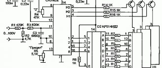
Here the main determining elements are the sensitivity of the measuring head, the resistance of resistors R10, R12 and R11, R13. Even more combinations may appear if, in addition to this, you experiment with the resistances of the resistors of the measuring circuit (R5, R6) and the transformation ratio Tr1 (within reasonable limits, of course). Before calibration, instead of resistors R10, R12 (R11, R13), variable resistors with values close to the expected values are installed, and the resistor slider R14 is set to the middle position. Then a resistor with a resistance corresponding to the end of the measuring range is connected to the measuring probes, and resistor R10 (R11) sets the arrow closer to the left side of the scale, where the last point of the measuring range will be. For obvious reasons, it cannot be in place of the mechanical zero of the microammeter. Next, short-circuit the probes and use resistor R12 (R13) to set the arrow to the far right mark of the scale. These operations are repeated several times until the arrow accurately positions itself at the start and end points of the range without our help. Now that we have “found” the boundaries of the measuring range, we measure the resistance of the corresponding variable resistors and solder constant ones in their place.
We find the intermediate points of the scale by connecting resistors of the corresponding resistances to the probes. To simplify the process, it is permissible for these purposes to use a resistance store with bifilar winding of coils. Subsequently, I checked the assembled device with the P33 magazine - the deviations in the readings turned out to be insignificant. To remember the location of intermediate points, it is not necessary to mark the scale with a pencil; it is enough to write down the numerical values obtained according to the factory scale on a piece of paper, then put the marks on the corresponding place of the template in the program.
Attached are my scale options made in Sprint. The file already contains a factory scale template, which can be enabled by checking the “display” box. The scale obtained in this way is glued to the factory scale using an adhesive stationery pencil.
DIY device
To test capacitors, you can assemble your own device. It will determine the capacity no worse than professional equipment. Assembling such a device with your own hands is quite simple. Using this device you can check the performance of any capacitive elements and even SMD.
The device will require the following parts:
- A microcircuit from the 555 series, for example, NE555 or the domestic analogue KR1006VI1. This microcircuit is a time timer, but in the device it will play the role of a generator.
- Resistors: R1 and R5 for 6.8 K. R12 for 12 K. R10 for 100 K. R2 and R6 for 51 K. R13 and R11 for 100 K. R3 and R7 for 68 K. R14 for 120 K. R4 and R8 for 510 K. R15 at 13 K.
- Capacitors: C1 with a capacity of 47nf, C2 with a capacity of 470pf, C3 with a capacity of 0.47 mkF.
- VD1 is suitable for any low power diode, for example, SOD 232.
- SA1 is any 5 position switch.
- Multimeter X1.
- Battery or power supply up to 12 volts.
Final version
Overall, the device turned out to be simply gorgeous and very convenient, and even if the parts for its assembly cost twice as much, I would still be able to safely recommend this EPS meter for assembly to all novice craftsmen who have a modest budget, or who want to save money and don't overpay. Happy repairs everyone! AKV.
- GRAPHIC VOLTAGE ANALYZER
- 4-POINT THERMOMETER
- THREE-PHASE WATTMETER WITH WIFI
Basic capacitor malfunctions
Capacitive elements play a large role in the circuit diagram of any device. Their main function is to charge a certain amount of current and pulse discharge into the circuit. The main malfunctions of capacitors include:
- Normal breakdown. A breakdown can be caused by an increase in operating voltage. Repair requires not only replacing the element, but also determining the cause of the high voltage.
- Internal break. If a radio component breaks, it loses its capacity, since both of its outputs become isolated. A break can occur when the device is dropped or the element itself is poorly assembled.
- A leak. This problem is due to the loss of some capacity. The smaller the permissible and optimal capacity, the smaller the charge size.
Useful tips
Testing a capacitor, especially a high voltage capacitor and a starting capacitor, involves some risk.
Before checking you should consider:
- If the electrical device is energized or has been disconnected for a short time, do not touch the printed circuit board in the area of the capacitors. The device will discharge upon contact and result in an electric shock.
- High-voltage capacitors must not be discharged with metal tools. A spark may occur and the uninsulated part of the object may receive an electric shock.
- The maximum test value for modern multimeters is 200 µF. It will not be possible to check a larger value.
- Elements with a capacity of less than 0.25 µF can only be tested for short circuits.
- When testing polar devices, it is important to identify the poles of the element. Connecting a tester with a change in poles can lead to failure of the capacitor itself.
When repairing electrical appliances of any power, safety precautions should be strictly observed. Checking any radio components can only be done with the device de-energized.
Setting up the measuring device
To make the correct adjustment, follow the instructions:
- First, symmetry of oscillations is achieved using resistor R 1. The “slider” of resistor R 5 is in the middle.
- The next step is to connect the 10 pf reference capacitor to the terminals marked cx. Using resistor R 5, move the microammeter needle to the corresponding scale of the capacitance of the reference capacitor.
- Next, the oscillation shape at the output of the generator is checked. Calibration is carried out on all subranges; resistors R 7 and R 11 are used here.
The mechanism of the device may be different. Size parameters depend on the type of microammeter. There are no special features when working with the device.