Just some three decades ago, not only in our country, but all over the world, in the spacious halls of design bureaus, numerous drawing boards stood in rows. Not much time has passed since then by historical standards, but it was enough to dramatically change the interiors of such design bureaus. Now the main working tool in them is the computer and its varied retinue in the form of peripherals, representing various printing devices. But in many design bureaus, somewhere in the corner you can still see old drawing boards standing in a pile, covered with dust. For our time, the drawing board has already become a full-fledged anachronism, the same, for example, as adding machines in the age of calculators. Some designers even have a similar old-fashioned drawing board at home, although they have long abandoned it and use computer programs. These “mammoths” of drafting have completely lost their practical use, and their time is hopelessly over.
Notes
- [kuhlmann-cnc.de/de/geschichte.html Website of the company Kuhlmann Werkzeugmaschinen+Service GmbH] This company acquired part of the assets of Franz Kuhlmann KG after the bankruptcy of the latter
- [dictionaries.rin.ru/cgi-bin/detail.pl?sel=word&word=%CA%D3%CB%DC%CC%C0%CD Kuhlman in the Big Encyclopedic Dictionary] In BES and the New Polytechnic Dictionary it is said that the name of the drawing The device comes from the name of the company that produced the devices, but the name of the company is given in the erroneous spelling Culmann.
- [www.freepatentsonline.com/RE28767.html United States Patent RE28767]
| This is a preliminary article about a tool or device. You can help the project by adding to it. |
History of invention
Kuhlmann was first produced by the German company Franz Kuhlmann KG
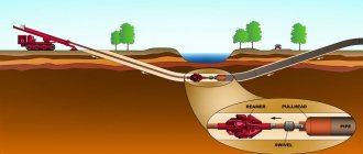
as a drawing device, consisting of a board, a lamp on a bracket and a pantograph - a sliding articulated frame in the form of a parallelogram. Before the advent of CAD based on a personal computer, the drawing board had no alternative, being an integral element of activity for design engineers, designers, and draftsmen.
Kuhlman
Kuhlman
E.O. » 24 Jul 2010, 02:05
I just talked with the grandson of that same Kuhlman (whose name has become a household name in the Republic of Armenia), and he told me a lot of interesting things about his grandfather, father, about their company, etc.
Looking at the “Kulman” article on Wikipedia, I found many inaccuracies there and immediately corrected them. In particular, it was stated that the device and the company that manufactured it were named after Carl Cullmann, when in fact they were named after Franz Kuhlmann. In this case, a link was given to the Big Encyclopedic Dictionary. I’m not at home right now, and I don’t have a paper version of the BES at hand, and I couldn’t open the Internet link.
It is interesting to know whether the BES really stated that the word “kuhlman” comes from “Cullmann”?
PS Request to German experts: please translate the wiki article “Franz Kuhlmann” into Russian (so that the link to Franz Kuhlmann from the “Kuhlmann” article would turn from red to real, blue). This article is very, very short.
In popular culture
- Kuhlman is portrayed by an Austrian-born American actress. Bibi Besh in the television film Victory at Entebbe
(1976). In the film, her character is German. - Kuhlmann is played by Austrian actress Sybil Danning in the film Mivtsa Yonatan
(1977; literally
Operation Jonathan
, called
Operation Thunderbolt
in English-speaking markets). In the film her name is Halima. - Kuhlmann is played by American actress Mariclair Costello in the television film. Raid on Entebbe
(1977). In the film, her character's name is Gabrielle Krieger. - Kuhlmann is portrayed by Katharina Schüttler in Carlos
(2010). - Kuhlman is portrayed by Rosamund Pike in Entebbe
(2018, titled
7 Days in Entebbe
in Canada and the United States).
Rulers and erasers
For drawing, it is better to arm yourself with 3 types of rulers:
- long – from 50 to 100 cm;
- medium – 30 cm;
- short – from 10 to 20 cm.
This set allows you to make any drawings. If you need to draw a line 50 cm long, it is more convenient to use a long ruler. And, conversely, for a 2 cm segment there is no need to bother with a meter-sized ruler. Buy plastic and metal products. Wooden ones can quickly deteriorate. Dents on the ribs will not allow you to draw straight lines. To construct curved lines, a pattern is required. This drawing tool is available with constant or variable curvature.
Products are made from the following materials:
- plastics;
- wood;
- metal
Steel is used to make patterns with variable curvature. Choose a tool that looks presentable. Then it can serve you for a long time.
Rulers for drawing
A drawing square is useful for drawing vertical and inclined lines. It is made from wood or plastic. The tool helps you build angles of 90, 30 or 45 degrees. It is convenient to have 2 squares: one with angles 90-45-45 degrees and 90-30-60 degrees. Any angles can be constructed using a protractor.
A high-quality eraser should erase a pencil well. A product that is too soft will quickly end, and a hard product will break. Try erasing the pencil mark. The paper should turn white again; if gray smeared marks remain on it, you should not use such an eraser. The eraser should be easy to clean and not scratch the paper. An eraser on the end of a pencil is also a good option.
Ruler
The second main tool of a draftsman is a ruler. Rulers are also divided by purpose. Ordinary wooden rulers work great when paired with a simple pencil. Mascara requires special rulers. Previously, wooden rulers with plastic inserts were produced. To outline a metal workpiece you need a metal ruler.
Reisshina
Have you seen a ruler on wheels? There is such an invention, and it’s called a reyshina. Using such a ruler, parallel lines are drawn. Various triangles are used to draw angles. Next come protractors, patterns - funny figures that look like a treble clef.
The line has another remarkable property. It can limit the length of the line. This is probably the main difference between a draftsman and an artist.
The simplest drawing kit
The flight of thought of a draftsman can always be measured and limited.
Eraser
But let's return to the pencil. This tool has a wonderful property. It is for this property that creative people love him. A line drawn with a pencil can be corrected using another wonderful tool - an eraser, or, simply put, an eraser.
Choosing suitable pencils
Pencils intended for drawing are indispensable when performing any work. The artist uses this tool both for sketching and for completing drawings. A pencil is necessary when creating a plan for a future building or piece of furniture.
These 2 letters in Russian markings mean (hard-soft). In the English version, medium hard-softness corresponds to the designation HB. The fact is that the beginner is not yet used to working with a pencil and feels pressure. Therefore, when drawing, even a high-quality eraser cannot remove incorrectly drawn lines. You can erase pencil marks, but it is impossible to remove the indented groove left by strong pressure.
Set of pencils and leads for drawing
After your hand gets used to working with the tool, you can switch to softer models. When it comes to drawing, hard pencils are the best choice.
It is important that their sharpening is carried out technically correctly. You need to learn how to hold a pencil in your hand correctly
Hard drafting tools leave light gray marks behind.
For the drawing it is important that there is more darkness in the shadows. It will take longer to draw with TM
Using a soft pencil allows you to do shading in one layer. Buy automatic products of 2 types:
- for drawing extension lines - a pencil with a 0.2 mm lead;
- for main lines - with a rod diameter of 0.5 mm.
Automatic pencils require replaceable refills. They are convenient to use: there is no need for sharpening.
Drawing pencils
There is a special series of pencils “Constructor”.
These are some of the best pencils for sketching and drawing projects.
Each pencil has its own special marking. And this is not without reason. Different lines are drawn with pencils of varying degrees of softness and hardness. Have you probably noticed letters and numbers on pencils: 2T, T, TM, M, 2M, 3M and even 5M? What do they mean?
This indicates the softness of the pencil lead. T - hard, TM - hard-soft, M - soft. The numbers indicate the degree of hardness or softness.
Let's say you need to shade a part with thin gray lines. A pencil marked 2T is suitable for this purpose. And if you need to draw a bold frame, then take a 3M pencil. It will allow you to apply a wide line in one pass. It is impossible to make such a line with a hard pencil. Foreign pencils are marked with the letters N and V. N - hard, HB - hard-soft, B - soft or bold.
Interactive drawing board as standard
Frame
- Floor-standing, vertical/horizontal arrangement with the ability to change the angle of the screen and the height of the display above the floor;
- Material: 2 mm steel, aluminum profile, glass.
Touchscreen
- Magnetic whiteboard;
- Touch screen - infrared;
- Screen diagonal - 77 inches;
- Multi-touch mode - from 6 to 32.
Audio system
- Two stereo speakers;
- Power (PMPO) - 10 W.
Control block
- Control board;
- Memory capacity - from 2000 / 4000 MB;
- Processor – Intel Celeron Dual-Core/ Intel core i5;
- GPU: Intel HD Graphics/Intel HD 4000;
- Storage – SSD/SDD, 60/120 GB.
Other characteristics
- OS - Android 4.4 KitKat;
- Operating temperatures - from -5° to +50°;
- Degree of protection - lp20;
- Warranty - 1 year;
- Service maintenance - 5 years.
Drawing devices
To speed up drawing work and improve its quality, various devices are used.
Reisshina
Reisshina
(German
Reißschiene
, from
reißen
- to draw and
Schiene
- tire, rail), a drawing ruler for drawing parallel lines with a transverse head at one end (Fig. 1).
There are leveling bars with a two-bar head (bar length 800–1400 mm) and with a single-bar head (500–750 mm). The working edge of the ruler for single-plane crossbars is oriented at an angle of 90° to the head.
A line with a two-bar head ensures that lines can be drawn at an angle at any angle. Tires are usually made from hardwood.
| Fig.1. Reisshina |
Hatching device
The hatching device is used to apply a large number of parallel lines at the same distance from each other (Fig. 2). The device consists of a ruler with a goniometric device, a mounting clip, a rod, and a drive lever with a return spring.
When you press the lever mounted on the rod, the rod carrying the holder with the ruler moves to a predetermined hatching step from 0.2 to 10 mm. The clip can be fixed at any point of the rod over a length of 100 mm. A goniometer with a lock ensures installation of the ruler at an angle from 0 to 180°.
The hatching device can be stand-alone, fixed anywhere in the drawing using fixing needles, or connected to a drawing device.
| Fig.2. Hatching device |
Drawing board
Drawing boards are made in various sizes and from soft woods. They serve for fastening drawing sheets of paper and special drawing devices (Fig. 3). The board should lie on the table with a slope of approximately 15-30°.
| Fig.3. Drawing board |
Pantograph
Pantograph (from Greek pan
, genus.
case pantos
- everything and ... graph), a device used for redrawing plans, maps, etc. on a different, usually smaller scale. Pantographs are manufactured in various sizes and different designs (hanging, on wheels, etc.). In Fig.
4 shows a so-called hanging pantograph, the weight of the rulers of which is partially compensated by the tension of the guy wires. The suspended pantograph has a softer, smoother movement compared to other designs and provides higher copy accuracy.
It consists of four pairs of parallel rulers connected to each other by hinges at points A
,
B
,
C
,
D
and forming a parallelogram
ABCD
.
Point A
(the pole) is stationary, at point
F
there is a spire that outlines the original, at point
K
there is a pencil that draws a smaller copy.
The ratio of the original and copy scales can be changed by moving the CD
along lines
AE
and
BF
;
K
must be moved so that points
A
,
K
and
F
are on the same straight line, thereby achieving similarity between the figures of the copy and the original.
| Fig.4. Pantograph |
Kuhlman
A drawing board is a drawing device for a pantograph system in the form of a board mounted vertically or at an angle. The name comes from the name of the German company Cullmann
, which produces these devices.
A drawing board is a precision device that provides the ability to draw straight lines of a given length at any angle in the plane of the drawing board. A pantograph-type device is used (Fig. 5,a), consisting of a system of levers hingedly connected in the form of a parallelogram, or a coordinate type (Fig.
5,b), having two mutually perpendicular profiles along which the carriages move. The parallelogram system and one of the carriages are equipped with a dividing (goniometer) head with two mutually perpendicular scale rulers. Rulers can have different scales and different lengths - horizontal is usually 500 mm, vertical 300 mm.
The goniometer head of the device provides angle reading accuracy up to 5′ (with fixation of the angle of rotation of the head after 15° or in any position), has two reading scales (direct and reverse) and a device for shifting them in order to construct projections at an angle. The device is equipped with a brake for fixing the position of the head, rotation from the plane of the board by 90°, devices for adjusting rulers, installing hatching devices, a printing device, etc.
| Fig.5. Kuhlman |
- Drawing / V.V. Stepankova, L.N. Anisimova, L.V. Kurtsaeva, A.I. Shershevskaya. – M.: Education, 2001. – 206 p.
- Drawing / N.S. Briling. – M.: Stroyizdat, 1989. – 420 p.
- Basics of drawing / L.A. Baranova, A.P. Pankevich. – M.: Higher School, 1982. – 351 p.
- Engineering graphics / A.I. Camp, E.A. Kolesnikova. – M.: Higher School, 1985. – 176 p.
- Soviet encyclopedic dictionary / Ch. ed. A.M. Prokhorov. – M.: Soviet Encyclopedia, 1987. – 1600 p.
Drawing tools
Details Category:
DRAWING TOOLS
, instruments by means of which the construction and production of drawings, plans, maps, diagrams, etc. are carried out. Drawing instruments include drawing boards, rulers, drawing bars, triangles, drawing boards of various designs, simple, proportional compasses, calipers, preparation tools, special devices for construction of conventional signs, patterns, stencils for inscribing drawings, brushes, pens, etc.
Drawing boards (Fig. 1) are used for sticking or otherwise strengthening drawing paper. Drawing boards are usually made in size 110 x 80 cm - and multiples of it from linden, alder or poplar wood; they are glued together from narrow boards with a mixture of wood glue and fish glue and equipped with transverse slats along the bottom or ends of the boards so that the board does not warp.
The requirements for drawing boards are as follows: 1) they must have a flat surface without knots, 2) be lightweight, 3) have regular straight edges converging at an angle of 90°, 4) they must not warp from wet and dry air, and 5 ) d.b. made of soft wood for easy insertion of buttons. For the convenience of draftsmen, special drawing tables are used that allow the drawing board to be given any position.
The most advanced drafting table systems (Fig. 2) are equipped with metal legs to give greater stability; they allow the board to be installed at any angle to the horizontal, and; she then might. placed at any height without the need to secure it, since the entire system is balanced by a load or spring.
Drawing rulers are made from various materials: wood, steel, iron, copper, aluminum, ebonite, celluloid, glass, helios, etc. Wooden rulers should be considered the best rulers for drawing work; they do not stain paper like iron or copper ones, do not lift paper fibers like ebonite ones, and are not flammable like celluloid ones. The best drawing rulers are made from stained solid pear wood or from pear wood with thin edges of mahogany or ebony attached to it at the edges. A good ruler should be about 70 cm long, about 5 cm wide and 2-2.5 mm thick (thin rulers are not very suitable for drawing purposes); its edges should be straight lines parallel to each other; the tree from which it is made, the ruler, not d.b. twisted, because such a ruler can easily warp. Before using a drawing ruler, it is necessary to check it as follows: 1) inspect the edges of the ruler for the presence of potholes and similar defects that interfere with work; 2) check the straightness of the edges of the ruler as follows: on a sheet of paper along one of the edges of the ruler MN (Fig. 3), draw a line mn with a finely sharpened pencil. Having turned the ruler 180°, apply it to the drawn line mn; if the edge of the ruler coincides with the drawn line along its entire length, then it can be considered correct.
The drawing board (Fig. 4) is used to draw parallel lines, using the edge of the drawing board as a guide; it basically consists of two rulers a and b attached to each other at right angles.
It is subject to the same requirements as a simple drawing ruler, with the addition of the requirement that the edges of the rulers be perpendicular. More advanced crossbars have a second transverse ruler, which can be placed and secured with a screw at any angle to draw inclined lines.
When working with drawing tables, the gauge is usually replaced by a ruler moving parallel to itself; its ends are usually guided by two strings or thin steel ropes a and b (Fig. 5), thrown through a series of blocks c attached to the board, so that the movement of one end always causes an equal and parallel movement of the other.
Triangles (Fig. 6a and 6b) are made from good stained pear wood, celluloid, helios, steel, copper, iron, etc. The most common and widespread in drawing work are wooden and celluloid triangles. Wooden triangles are usually made from rulers of pear, black, mahogany or rosewood glued together.
These triangles are made 2.5-3 mm thick, with harder wood (black, red) bordering the outer sides of the triangle. Triangles made of pear wood with celluloid transparent edges a (Fig. 7) are very convenient, and the latter are much thinner than the triangle itself, etc. do not come into contact with the paper, which greatly reduces the risk of ink leaking under the edge of the triangle when drawing thick lines.
Most manufactured triangles are rectangular with angles of 60 and 30° (Fig. 6a) or 45° (Fig. 6b). Triangles must satisfy the following conditions: 1) the edges of the triangle must be straight and free of potholes and cracks; verification is carried out in the light between the edges of an accurate ruler and a triangle; 2) one of the angles of the triangle d.b. straight. For verification, a verified ruler is laid on a sheet of paper, to the edge of which a triangle is then applied with the smaller leg (Fig. 8); then along the edge of the larger leg of triangle H a line ab is drawn on paper.
After this, without moving the ruler, the triangle is rotated so that it takes position H1, after which a second line is drawn along the edge of the larger leg: the coincidence of the newly drawn line with the first proves the correctness of the right angle. To check the correctness of the angle of 30°, proceed as follows: apply the verified triangle with leg ab to the edge of the verified ruler (Fig. 9, A) and draw a line along the hypotenuse cb, then rotate the triangle near edge cb and again draw a line along the edge of leg ab.
After this, the triangle is laid so that its side cb coincides with the second drawn line, and then drawn along the leg ab to the third line; if, by applying a verified triangle to the edge of the ruler, the drawn line coincides with the leg of the latter, then the verified angle of the triangle is correct. In the same way, the correct angle of the triangle is checked at 45° (Fig. 9, B). The 60° triangle angle is checked using the method shown in Fig. 10, giving the triangle positions I, II and III.
At the correct angle, line ABC d.b. straight. In addition to the described triangles with constant angles, special triangles with one movable side equipped with a protractor are currently being produced (Fig. 11a).
In connection with the parallel ruler described above, a sliding square (Fig. 11b) is convenient, fixed in any position with lever a and allowing you to draw a series of inclined parallel lines.
Recently, in mechanical engineering and architectural drawing, drawing machines (Fig. 12), which are basically a protractor held parallel to itself during all movements, have become increasingly widespread (for good machines, the angular error when moving from one end of the board to the other is not exceeds several minutes) using two pairs of rods b, b of equal length.
Two replaceable scale rulers g, r are hinged to the protractor, they are always at right angles to each other and can be set at any angle using the protractor and clamped in this position. The correct values of the most common angles after 15° are ensured by a latch that fits into the cutouts of the protractor. Rulers g, g m. b. quickly replaced when changing the scale of the drawing. Using a drawing machine instead of a grid and a triangle significantly increases (up to 100%) the productivity of drawing work.
Drawing patterns are curved rulers for drawing those curves that cannot be used. constructed using a circular compass. Usually for drawing work you need to have a whole set of patterns. The large number of individual patterns in the set forced us to switch to patterns with varying curvature.
In fig. 13 shows a pattern consisting of a flexible steel strip a
, to which the racks
b
;
tubes c, c are hingedly attached to the latter, into which the ends of screws d
with right and left threads are screwed.
By rotating the head, the screws are screwed into the tubes and bend the steel strip in the required manner. More convenient and easier to use is the pattern (Fig. 14), which retains the curvature given to it; it consists of a split lead core a
b
superimposed on it ;
all this is surrounded by a layer of
.
The friction between the lead core and the steel inserts is high enough for the pattern to maintain its position once given to it. In shipbuilding drawing, flexible slats are used to draw smooth curves .
(Fig. 16), bent along the points of this curve and held in place by weights
b
.
The drawing pen is designed for drawing lines in ink; it consists of two or three (for drawing particularly thick lines) elastic steel plates, or blades, and
and
b
(Fig. 17, A), inserted into the handle
c
.
The free ends of the blades are pointed. r
passing through the blades serves to bring them closer together; using it you can change the thickness of the line drawn by the drawing pen.
For ease of cleaning, the drawing feeders are equipped with a movable blade; two designs are used: 1) a hinged folding blade (Fig. 17, B) and 2) the more common - rotating one (Fig. 17, C).
Sometimes the drawing boards are equipped with a spring leg that is spread far apart, and to clean it it is enough to move the lever a
(Fig. 18a), serving as a support for the head of the screw
b
; The described device ensures that the drawing board remains unchanged after cleaning.
To draw particularly thick lines, there are special drawing feeders equipped with one or two additional blades. To draw two parallel lines simultaneously, there are double drawing feeders mounted on one handle (Fig. 18b) and installed at the required distance using screw a
.
To draw lines of medium thickness (up to 1 mm), drawing pens with especially wide blades (Fig. 19) are advantageously used, holding a large amount of carcass and not requiring frequent filling.
For the same purpose, a drawing pen has recently been designed, its design reminiscent of an eternal pen. In fig. Figure 20 shows its external view and longitudinal section, where a is a handle serving as a reservoir for mascara, b is a channel for injecting air into the tube, c is a supply cap, d is a socket for a replaceable drawing pen, e is a plunger, f is a tube for mascara, g - nut for the oil seal.
Filling the pen with ink is done by pressing the cap e, and the stroke of the plunger, and, consequently, the size of the drop sent into the pen, is determined by the depth of the slot on which the cap is placed; acceleration of work when using this drawing board is ensured only on the condition that the feeding mechanism works without interruptions, otherwise all the time saved will be spent on cleaning, adjusting and setting up this eternal drawing board. Filling pens with ink is done using a goose feather, which is attached to the stopper that closes the bottle of ink. When choosing drawing boards, preference should be given to drawing boards made from a single piece of steel, since all folding legs are used. or m. will soon become loose.
The ends of the drawing board d. b. of the same length, well and correctly finished. The screw must connect the blades correctly, have a deep groove, operate freely, and even with a slight turn of its head, change the distance between the ends of the blades. To draw curved lines along a pattern, a special curved-legged drawing pen is used (Fig. 21), designed so that it can rotate around an axis, due to which the same thickness of the line is achieved during sharp turns.
To draw dotted lines that require uniformity in the size of the dotted line and the gaps between them, special dotted drawing pens are made (Fig. 22), in which the pen itself is
attached to the end of a lever
b
, raised to interrupt the line by a figured wheel
c
, driven into rotation by a gear wheel
g
, rolling along a ruler or crossbar; These drawing boards, however, are used very rarely in practice, since they require quite careful care and skill in handling them.
Compasses should be divided into three groups: 1) dividing, or marking, 2) circular and 3) calipers. A dividing or marking compass of the Swiss type (Fig. 23a) has two legs connected in the head by a through bolt, which serves as the axis of rotation of the legs; to line a
from the hinge the legs are made of brass or nickel silver, and below the line a to the end - of hardened steel.
The design described above is not entirely practical, because it does not allow replacing broken legs. Compasses of the Richter system are considered to be of a more advanced design (Fig. 23b and 23c). The head of the Richter compass consists of a clasping clamp a
and two rivets
b
, passing through the legs and resting on the clamp with a ball head;
the clamp is tightened with a screw in
, with which you can adjust the ease of movement of the legs.
At the ends of the legs (Fig. 23c) there are two sockets into which replaceable steel needles are inserted, secured with special screws. The disadvantages of Richter compasses include the fact that over time, the supporting surfaces of the rivets are developed and the ends of the legs no longer coincide. For special purposes, dividing compasses with three legs are made (Fig. 24).
The circular compass (Fig. 25) differs from the described dividing compass only in that the lower part a
one of his legs maybe.
taken out and replaced by another part, namely, a leg with a pencil b
, a circular drawing pen
c
or without an
extension leg Replaceable legs are secured with a screw d
.
The caliper (Fig. 26a) is a spring compass, the opening of which is set with a screw with right and left threads a
, which allows you to achieve greater accuracy. To draw circles of small diameter, callipers with replaceable inserts are made.
The rivet caliper (Fig. 26b) is used for drawing circles of very small diameter; it consists of a needle leg and
, which freely passes through tube
b
, which carries on a second spring leg a pencil
d
or a circular pen
d
.
To draw a circle, place needle a
in the center and impart
rotational movement b This compass greatly speeds up drawing when there are a large number of circles of small diameter, for example, rivets in construction drawings.
To draw circles of very large diameter, a caliper is used (Fig. 27), consisting of a
, on which a fixed center
b
and a movable slider
c
, in which conventional inserts are fixed.
For calipers of very long length, and therefore weight, the end of the rod is supported by a stand on wheels. To accurately set the diameter, the fixed center is moved within small limits with a micrometric screw g
. The requirements for compasses when purchasing them are the following: 1) the head hinge should not be weak, otherwise when drawing circles a spiral will be obtained, 2) the inserts (pencil, drawing pen and extension leg) should not wobble in the sockets and 3) the needles of the legs must be sharpened, otherwise they will tear the paper.
Proportional compasses (Fig. 28, A and B) are used to change the removed length in an arbitrary ratio, to divide lines and circles. This is achieved by moving the axis of rotation of the compass along its legs.
It is obvious that when it opens, the ratio of the distances between the tips of both ends will be constant and equal to the ratio of the length from the ends of the legs to the axis of rotation. The most common ratios of linear dimensions, as well as the ratio of the sides of the n-gon to the diameter of the circumscribed circle, are marked on the legs of the compass with dashes along which the movable stage a
, carrying the axis of the compass.
Sometimes the slide is equipped with a gear, which is driven into rotation by head b
and moves the slide along the gear rack
on
the leg of the compass;
Screw g
secures the rocker motionless in this position. Since any change in the lengths of the legs of the proportional compass violates the accuracy of the calibration, the most advanced models are equipped with angular legs (Fig. 28, B), allowing for sharpening and sharpening of the ends without changing the working length of the legs. A proportional compass greatly speeds up the work of the draftsman, since it makes it possible to take dimensions from a drawing or directly and gives mechanically, without calculations and secondary measurements, the required dimensions increased or decreased according to the taken scales, which can be used. applied directly to the drawing.
The preparation kit is a set of drawing tools placed in a special box-case. Drawing work is carried out mainly with a compass with graphite or a circular pen and drawing pen. Therefore, for the majority of service personnel there is no need at all to have bulky ready-tools, and in large drafting rooms it would be more expedient to keep the tool not in large ready-to-use sets for each employee, but to combine all the items of the same name from the ready-to-use sets, supplying the draftsmen with the necessary number of these individual tools. This would make it easier to record and repair instruments. To save drawing tools, it is necessary to take the following measures: 1) you should not leave ink dried on the blades of the drawing pen, nor should you clean it off with a knife or other hard object, or, even worse, remove it with sandpaper; 2) to remove dried ink from the pens, wet the ends of the pen in warm water and wipe them with chamois; 3) the airfeeders should not be left with the flaps tightly compressed: the blades should be located at a considerable distance from each other; 4) the hinges and screws of drawing tools must be lubricated with oil (bone) from time to time; 5) the entire cooking utensil must be kept in a dry place and its parts must be protected from possible rust; 6) after working with the preparation tool, it is necessary to wipe all used tools with suede and place them in the appropriate slots of the case; 7) in no case should you draw on drawing pens with ordinary ink, since after this the drawing pens easily rust and the ink in them will curl up.
Other drawing tools include: brushes for coloring drawings, drawing pens and for inscriptions, utensils for diluting ink and paints. Paints are applied to paper using special drawing brushes made from ferret, kolinsky or squirrel wool. The frame of the brushes is made of metal. Brushes are made in different numbers (Fig. 29).
When choosing a brush, you usually try it by dipping it in clean water; The end of a good brush is made finely pointed and does not crumble with light pressure.
Various pens are used for inscriptions on drawings: for small inscriptions - small pens; For inscriptions in italics, it is recommended to use ordinary pens No. 86; to make inscriptions in rondo font, pens of different thicknesses are used, as well as double and triple parallel ones (Fig. 30); For inscriptions in normal font, metal or glass tubes are convenient.
To rub ink and dilute paints, you need to have two or more saucers with a smooth bottom and tightly ground edges. Convenient saucers are placed one on top of the other in the form of a stack (Fig. 31); Such saucers are suitable for ink and paint.
Drawing instruments include: stencils and templates for drawing standard parts, bolts and nuts, stencils for labeling drawings, etc.; They are made of transparent celluloid, which makes them easier to work with. In fig. 32 shows two types of stencils with holes of different sizes cut out in them for making inscriptions in a normal font; the method of forming each letter is given at the bottom of Fig. 32.
Experience working with them did not give positive results, and draftsmen who have mastered this font prefer to write without stencils - by hand. Stencils for quickly drawing nuts are very convenient, which are made for two projections of the nuts - for the front (Fig. 33a) and side (Fig. 33b) views of the nut.
These templates give not only the outlines of the contours of the nut curves with their centers a, b and c, but also the four points d and d, giving the outer and inner diameter of the thread. As a simple but convenient device for practice, we can recommend a stencil with cutouts of various shapes for applying to the drawing when wiping small lines with an elastic band so as not to touch adjacent ones. A protractor is used to construct and measure angles on plans. A simple protractor (Fig. 34a) consists of a semicircle attached to a ruler, on which degree divisions are marked.
Readings using such a protractor can be made with an accuracy of up to 15′; the center of the protractor circle is marked on the inner bevel of the ruler with a line or cutout. Protractors are made from copper, nickel silver, celluloid, aluminum and even printed on cardboard. The tacheometric (circular) protractor (Fig. 34b) is a normal protractor extended to 360°.
For greater accuracy in constructing angles, a protractor with an alidade is used (Fig. 35), which is a simple protractor of a larger diameter (20-25 cm), equipped with a rotating alidade ruler a with a vernier b, which allows you to construct and measure angles with an accuracy of 1-2′.
A good protractor requires: 1) equality of the degree divisions marked on it, 2) parallelism of the diameter of the semicircle to the lower edge of the ruler, 3) coincidence of the outer curve with the circle with the center marked at the upper edge of the ruler. Circular protractors are required that the mutually perpendicular diameters passing through the 0-180°, or 0-0° and 90-270° or 90-90° divisions intersect at the center of the slot and align with the cross engraved on the inserted celluloid.
For protractors with an alidade, it is also required that the beveled edges of the alidade be parallel to each other and to the line connecting the center of the protractor to 0° of the vernier. For perspective drawings, in which it is often necessary to draw a large number of lines intersecting at one point lying far outside the drawing field, a special ruler is used, consisting of three rulers hingedly connected to each other
,
b
and
c
(Fig. 36), of which ruler
c
serves to draw lines along it, and
a
and
b
slide along pins
g
1,
d
2, stuck into the drawing board.
Due to constancy (with a given installation of movable rulers a
and
b
) angles α1 and α2 (Fig. 37), straight line
c
passes for all positions of the system of rulers
a
,
b
,
c
through a constant point A lying on the circle defined by points
g
1,
g
2 and point B of the intersection of straight lines
a
and
b
.
Source: Martens. Technical encyclopedia. Volume 25 - 1934
- < Back
- Forward >
And from the platform they say - Revit...
AutoCAD is a platform and Revit is a different platform. This means that when starting a relationship with Revit, the first thing you should do is forget the AutoCAD ideology. The Americans based this platform on the principle of the building information model (object) Building Information Model (BIM). In essence, this is almost a database of the designed object with its simultaneous graphic display.
In Revit, the designer always works in three-dimensional space. Views in Revit are simply a matter of changing your point of view. Whatever you work with - perspective, section, facade - you always work with volume. Moreover, it is also an information model. Because the tool contains an inextricable and bidirectional mechanism for communication between the graphical display of an object and specifications. And you can influence the appearance and layout of the object from the specification. For example, changing one type of window or door to another. Changes to the model occur automatically. This is the so-called “Beam” approach.
Revit is frankly good at the ease of creating the design part. Due to what? Sometimes it’s even difficult to explain. The factor of individual perception plays a role. Something akin to the feeling you get from the interior of a car you like: you just understand - it’s very comfortable, it’s yours. Experts who have tried to understand this issue call this quality ergonomics. So, Revit is precisely an ergonomic package. Among our clients there are users who are openly in love with Revit and completely dislike AutoCAD. Some of them do conceptual design and submit projects in Revit, and draw up drawings in AutoCAD. The explanation is simple: Revit does not have applications that would help produce drawings according to our standards. It is no coincidence that the product is called AutoCAD Revit.
It is in vain to look for echoes of AutoCAD in Revit. These are completely different packages, it’s not for nothing that they are called platforms. We would say that Revit is a different principle and a different approach to design. If in AutoCAD it is the user who actually does the drawing, then in Revit these functions are largely performed by the software product itself. If you don't have much experience with AutoCAD yet, it's easier to get used to Revit right away. The exception is made by specialists who, in principle, live and work flexibly, are flexible, easily adaptable, and are prone to constant learning and creativity. For them, switching from AutoCAD to Revit will be an exciting adventure, like moving to the next level in a computer game.
However, we would like to remind you once again that all Autodesk vertical products require configuration. This cannot be avoided in any of the platforms, be it Revit or AutoCAD. You need to be prepared for certain efforts, for active involvement in the process of preparing the instrument - and take it calmly. When choosing software solutions, you need to understand that the effect you get from using the purchased product directly depends on the accuracy of its customization to the structure and tasks of a particular organization
In addition, it is very important not to spare resources on employee training
The selection of workstations, as well as the choice of platform, is the exclusive right of the customer. But the company will most likely need help with this (this usually happens).
The views of those who have observed the experience of many other organizations, the balanced arguments of specialists who understand each package in detail, have studied its strengths and weaknesses, the features of linking it to the tasks of various companies - all this can be very useful, and ultimately save money, time and nerves…
We have tried to offer options and relieve users of unnecessary stress when faced with the task of choosing design tools. If this information turns out to be useful to someone, we can consider our mission accomplished. We will also be waiting for questions, requests for consultations or training, proposals for cooperation by phone. +7 (812) 496−6929 and by email [email protected]
Features of use[ | ]
Kuhlman dictated the design technology - a sheet of paper attached to the drawing board was used as the basis for the design, therefore the development was carried out in separate planes: front view, side view, top view. At the same time, CAD allows you to design in three dimensions at once, including using the reverse approach, starting the development of a three-dimensional model (tool, die, mechanism) and then creating separate drawings for a specific plane and a separate view.
At the moment, the level of use of drawing boards as a design tool at Russian enterprises is close to zero, since CAD significantly reduces development time and, with a sufficient level of training for the designer, makes his work disproportionately easier.
The main element of a drawing set is a compass
The following components are distinguished in the compass:
- holder;
- two rods with fastenings;
- nozzles with needles for drawing or drawing.
In accordance with the age characteristics of consumers, compasses are:
- educational (for school, as well as colleges and universities);
- professional.
More information about the components of the compass and its dimensions
The length of the product depends on the age of those for whom the instrument is purchased:
- for models intended for training – no more than 12 cm;
- for products intended for middle school students - 12-13 cm;
- for instruments recommended for high school students – 13-15 cm;
- for creating professional drawings, a suitable value is more than 14 cm.
Compass and rod holder
The holder is made of plastic.
Barbells for children can be made of plastic. These compasses are bright and light. To carry out drawings, it is better to choose rods made of brass and its alloys. The classic model with solid steel parts provides optimal accuracy as long as the parts do not wobble. Modern models of compasses have special clamps for rods. These are levers with hinges or screw fastenings.
A high-quality compass can be easily identified if you test it when purchasing: its rods sit tightly in the grooves and do not wobble.
Needles and attachments
The needles are also responsible for the accuracy of the measurements.
Various compass designs
If the compass is used for training purposes, the tip of the needle is not too sharp, which helps prevent injury. Such a needle does not hold the reference point well. In professional models, the needle tips are sharp.
If you plan to use the tool every day, choose a model with a replaceable needle rather than a welded one. Special built-in covers allow you to protect your hands from contact with the needle. The advantage of replaceable or replaceable needles is that it can be quickly changed if it becomes dull and even sharpened.
Compass attachments are the last important detail. They come in 3 types: With a mechanical pencil with a lead diameter of 0.5 mm; with universal holder; with 2 mm lead
Leads for compasses
The first variety is considered the most unassuming. The second attachment is called a “goat leg”: a pencil acts as a drawing tool. The third is professional. It is not convenient for schoolchildren. You have to additionally buy a “refill” for the compass.
Characteristics of a professional drawing set
The builder uses a preparation room with a large number of items:
- 3 types of compasses – standard, large and with a falling needle;
- screwdriver;
- pencil holders;
- mechanical pencils;
- extension cords;
- containers with spare wheels, needles and leads;
- centric;
- needle with holder.
Professional drawing set
The compass copes with various tasks. Without this tool it is impossible to draw an arc or circle. It has a needle on one leg, and a writing element on the second. The compasses are made of metal. The tool can be used for navigation: it helps to accurately measure the distance between two points or objects on a plan or map. The measuring compass has needles at the ends of both metal legs.
There are many offers on the market, but if you want to find a really high-quality set, you will have to try. One of the well-known and reliable manufacturers can be considered, for example, Koh-I-Noor. By purchasing products from well-established brands, you have a better chance of buying a quality compass.
Device
A drawing board is a precision device that makes it possible to draw straight lines of a given length at any angle in the plane of the drawing board. A pantograph-type device is used, consisting of a system of levers hingedly connected in the form of a parallelogram, or a coordinate type, having two mutually perpendicular profiles along which the carriages move. The parallelogram system and one of the carriages are equipped with a dividing (goniometer) head with two mutually perpendicular scale rulers. Rulers can have different scales and different lengths - horizontal is usually 500 mm, vertical 300 mm. Rulers are made of metal-reinforced plastic or thin-walled steel profile. The goniometer head of the device provides angle reading accuracy up to 5′ (with fixation of the angle of rotation of the head after 15° or in any position), has two reading scales (direct and reverse) and a device for shifting them in order to construct projections at an angle. The device is equipped with a brake for fixing the position of the head, rotation from the plane of the board by 90°, devices for adjusting rulers, installing hatching devices, a printing device, etc.
Do-it-yourself drawing board - Metalworker's Handbook
Are you here
Just some three decades ago, not only in our country, but all over the world, in the spacious halls of design bureaus there were rows of numerous drawing boards.
Not much time has passed since then by historical standards, but it was enough to dramatically change the interiors of such design bureaus. Now the main working tool in them is the computer and its varied retinue in the form of peripherals, representing various printing devices.
But in many design bureaus, somewhere in the corner you can still see old drawing boards standing in a pile, covered with dust. For our time, the drawing board has already become a full-fledged anachronism, the same, for example, as adding machines in the age of calculators.
Some designers even have a similar old-fashioned drawing board at home, although they have long abandoned it and use computer programs. These “mammoths” of drafting have completely lost their practical use, and their time is hopelessly over.
What is a drawing board?
The younger generation will probably need to see a photocoil to understand what we are talking about. A drawing board is a drawing device that has a pantograph system and is a rectangular wooden board that can be installed vertically or at any angle.
History of the invention of the drawing board
At one time, these devices were manufactured by a German company, which, like the device itself, inherited the name from its inventor and founder Franz Kuhlmann. Although there is another (admittedly erroneous) version that this drawing device was invented by another German engineer Karl Kuhlmann.
So, having invented this graphic tool, which includes a drawing board, a pantograph - a metal parallelogram frame with movable articulated joints and a lamp mounted on a bracket, Franz Kuhlmann founded, which began to produce these products for the whole world. Until personal computers appeared and computer-aided design (CAD) programs were created for them, the drawing board had no alternative - it was the main working tool for an army of draftsmen, designers and design engineers.
Drawing board device
It is unlikely that anyone would think of making a drawing board with their own hands, since it is much more difficult than making an easel.
Despite its bulkiness, the drawing board is a fairly accurate mechanical device that allows you to draw straight lines of arbitrary length and at arbitrary angles in the plane of the board.
The device could have two options for a movable frame:
- the pantograph mechanism was a system of steel levers that formed a parallelogram through articulated joints;
- a coordinate-type mechanism with two strictly perpendicular profiles along which the carriage could move.
A goniometer (dividing) head was attached to the parallelogram or one of the carriages, from which two scale rulers emanated at an angle of 90 degrees. The rulers were usually marked with different scales, and they themselves were of unequal length: the vertical one had a length of 300 mm, and the horizontal one had a length of 500 mm.
Rulers were made from metal-reinforced transparent plastic or thin-walled steel profile. The accuracy of the goniometer head was 5′, and its position could be fixed in any position. Direct and reverse reference scales were used simultaneously.
Using a device for displacing the head, projections were constructed at an angle. The device is equipped with a brake that fixes the position of the head. The head can be rotated perpendicular to the plane of the board.
The installation of a printing device, shading devices, tools for adjusting rulers, etc. was provided.
Features of the drawing board operation
Since design using a drawing board was carried out on whatman paper, it was carried out in three planes:
- front view;
- side view;
- view from above.
The CAD system created later made it possible to immediately make three-dimensional projections and often used the reverse approach, when, after creating a three-dimensional model of the part, its individual projections were created.
Electronic drawing boards
Currently, drawing boards are used less and less as design tools in design bureaus and at Russian enterprises, since they cannot compete with CAD in terms of development speed, and they also significantly facilitate the designer’s work. And although the ordinary mechanical drawing board has given way, it has been replaced by an electronic drawing board in different variations.
Workplace of a Soviet engineer
cccp_foto mgsupgs
The original was taken from
mgsupgs
in the Workplace of a Soviet engineer. Based on dismantling the cabinet drawers, a small illustrated post was created,
about how and what Soviet engineers worked in the 80s.
So, first, the boards and drawing boards: The most typical Robotron drawing board, it was found quite often. It worked reliably. But it was far from Reissov’s, there was no such smoothness and clarity in fixing the Robotron line, it was not found often, at least in construction PIs. But quite often I came across Lapa, made in our country, and instead of it, many preferred a classic board with a tie bar. By the way, the photo shows an advanced fastening of the tie bar. This is a classic fastening, it requires precise positioning of the sheet relative to the tie bar, the position of which is set once and for all. True, you can tighten the lines... In reality it looks like like this. A typical student's board, by the way. And the above-mentioned advanced tension meant fixing the fishing line only at two lower points, due to this the rod could move relative to the edge of the board by about 25-30 degrees. or the technical school should urgently attend to the purchase of a board or drawing board. Although I know a few unique people who graduated from university on the kitchen table... With the help of an inertial plane and some kind of mother.
Now get ready
Of course, there were also Soviet ones, they were issued, but a normal engineer would get imported ones. There were also preparation rooms for students: In addition, preparation stations varied in the number of items, but the usual one was enough for me.
Well, now - what did you paint with (namely, paint)...
So, regularly all engineers were given pencils like this. For unknown reasons, their quality left much to be desired, so I drew with them from early childhood, and for work I bought Kohinorov with my own. Erasers were also bought or otherwise got Kohinorov’s or, if you brought them, Faber’s ones... Chic in the 70s - 80s -x were considered to be Czech collet pencils with original cores.
Like Cooking Tools and other goodies, they were kept under lock and key, and often taken home. But they still had to be sharpened, and by the end of the 80s they were replaced by completely modern ones with polymer rods of different thicknesses. Ordinary pencils required sharpening. Some were able to use milling machines, but I sharpened with a spatula and therefore only with a razor.
Ink work.
In principle, with a certain skill, it was possible to quickly work with pens and drawing pens. But GDR scribers had already appeared. By the way, from the point of view of reliability, rotrings are worse, IMHO.
Well, now the rulers.
Of course, rulers also had to be imported, but some devices were made to order. For example, a washing stencil that lies on top of a pile of rulers. There were, indeed, the most necessary rulers that had no imported analogues. A typical set of rulers from the 70s, later they began to issue plastic.
What did they count on...
I didn’t catch the calculus era in engineering, although saleswomen in stores used them widely. But I managed to use Felix to my heart’s content... True, at school, because calculators cost exorbitant amounts of money.
In addition, I mastered the logarithm and even acquired a pocket racer... Then there were several Soviet machines that broke down and got lost with enviable regularity, until I got this device. Note - it works...
And in the late 80s I switched to a large calculator...
Now pens and stuff.
The main problem with the Soviet ballpoint pen was the refill. That is, when buying refills in a store, you had to check each one, otherwise up to half might turn out to be non-writing. Therefore, each imported pen was cherished as the apple of the eye, the refills of disposable BICs were refilled in a metal repair shop. They also cut valves into disposable lighters.
In the USSR, paper clips and hole punches were made with high quality, but everyone looked for GDR ribbon for typewriters, and painted it if it dried out. By the way, this continued in the era of dot matrix printers... Where would you be in an office without scissors? Good inexpensive scissors, as well as knives, could not be taken away from this. Although the Swiss ones are of course better, they cost a lot more money..
But the buttons are only from Riga! The ink had to be looked for in glass, because clots appeared in the plastic containers, which threatened to completely wash out the fountain pens. A typical folder for papers from the times of the USSR, there were also plastic envelopes... Well, this is all that is left of that one for me era, I didn’t get the board out. Sorry if I forgot something.
Everything I remember about the USSR can be read here.
cccp_foto visualhistory
American Life magazine photographer Howard Sohurek traveled throughout the Soviet Union in the late 1950s and left an impressive collection of color photographs, comparable in scope to the Prokudin-Gorsky collection. On the Life magazine website, photographs taken by Sohurek in Tbilisi are dated 1958 ., but by analogy with the photographs of Kiev, it can be assumed that in reality they could be even earlier - 1957. Although, according to information found on the Internet, the cable car to Mount Mtatsminda was built and opened in 1958: Larger image Operation of this road ended on June 1, 1990 with a monstrous catastrophe. I have not yet been to Tbilisi, I hardly know the city, so I would be grateful for any clarifications on the names of the pictures.
Boys on the bank of the river. Chickens:
It is curious that Sokhurek’s subjects are very similar to the subjects of Prokudin-Gorsoky’s Tiflis photographs. The latter has a view of the rocky bank of the Kura River with old houses just above the cliff, almost like in this photo: This landscape is probably one of the most striking images of the city: Larger image View of the fortress across the Kura River: The same view, only horizontally: Larger imageAnother similar shot: Larger imageThen there is a series of panoramic shots of the city from the top of the mountain:The uniqueness of the landscape determines the unique and picturesque appearance of this city:Larger imageMoon over the city:
Larger image
Unfortunately, there are fewer photographs from 1958 than we would like, but we will continue the theme of old Tbilisi.
Biography
Leen Kuhlman was born on January 31, 1920 in Tartu, the sixth child in the large family of shoemaker Andres Kuhlman. In 1927, she entered the 1st Tartu City School, where she studied until 1931, then studied at the 5th Tartu School, which she graduated in 1933, and the Tallinn Pedagogical College.
In 1932, Lehan’s father died, leaving five young children dependent on her mother; in the same year, the girl’s closest friend, Maiga Berzin, whose parents adopted the girl, also died.
After Estonia joined the USSR, she joined the Komsomol and studied at the Tallinn Pedagogical Institute. In 1941, Lehan received the specialty of a junior high school teacher.
In March 1941, she began working as a Komsomol organizer of the 4th Tallinn secondary school.
With the beginning of the Great Patriotic War, she went to the military registration and enlistment office and asked to be sent to the front, but she was refused. Since August 1941, while evacuated, she worked on the Leninsky Put collective farm in the Nyazepetrovsky district of the Chelyabinsk region.
In January 1942, she joined the Red Army as a soldier in the medical battalion of the 7th Estonian Rifle Division. Later she was sent to Leningrad and, under the name of Linda Tulliman, was trained at an intelligence school.
On the night of September 13-14, 1942, she was parachuted behind enemy lines near the city of Tartu. In Tartu she settled with her sister. Its task was to monitor the movement of Wehrmacht troops in the area of Lake Peipsi and the enemy naval forces in the port of Pärnu.
In the period from September 14, 1942 to January 2, 1943, Leen Kuhlman transmitted several dozen radiograms about the situation in Pärnu, Tallinn, Tartumaa and Võrumaa counties of Estonia to the headquarters of the Baltic Fleet. Based on its data, a Soviet submarine sank a German transport in the Pärnu area. Among the information that Leen Kuhlman collected and transmitted: information about the absence of large enemy ships on Lake Peipsi, data on the protection of the coast in the Mustvee-Vasknarva section, the nature and quantity of weapons of the “Estonian Legion” units.
On January 2, 1943, Leen Kulman was arrested in the Ojaere farmstead near the village of Luutsniku in the Võru region, where her sister and her husband lived. All her relatives were arrested along with her: her sister Olga Mägi and her husband August Mägi, as well as her sisters and mother in Tartu.
During a search, a transmitter was found in the mattress. Leen was placed at the disposal of the political police of the city of Võru, and on January 4, 1943, transferred to the external detective police in Pskov as a Soviet intelligence officer.
On March 6, 1943, she was shot by a fascist from the Omakaitse organization.
Evgenia Katseva, who taught Lehen radio, recalled:
Quirin Kulman, heretic in Muscovy
Quirin Kuhlman was born in 1651 in the Austrian city of Breslau (now Polish Wroclaw).
The boy was in poor health and spent his entire childhood in the city library. After graduating from high school, he became very seriously ill and miraculously survived. Apparently he suffered from some kind of severe meningitis, because for the next five years Kuhlman claimed that two angels constantly followed him.
Hallucinations did not prevent him from writing poetry. Kuhlmann's collection of sonnets “Heavenly Kisses of Love” became famous in Europe and received significant awards. Here is an example of the beginning of one sonnet:
Twenty-third kiss of love
O night! Great night! O night is brighter than day!
O night! O light! And a light greater than the sun!
O night! In the circle of times there is only one such night!
O night! The miracle will open in all its glory!
In the 17th century, people liked Kuhlman's work.
He showed great promise, studied law at the University of Jena for three years, but then the angels took their toll: Kuhlman abandoned his studies and plunged headlong into the works of the German mystic Jacob Boehme, who made a tremendous impression on Quirin.
Boehme developed the ideas of the recent Reformation even more radically. If Lutherans rejected the magnificent Catholic Church, communicating with God without intermediaries and focusing on the Bible, then for Boehme the Bible was not an authority. He believed that a spark of God lives in every person, and therefore in life one must focus on the inner voice - it is the voice of God...
And Quirin Kulman began to focus on his inner voice. He soon came to the firm conviction that he was the “Son of the Son of God” and was sent into this world to “destroy Babylon and build a Jezelite kingdom in which people will live as before the Fall of Adam.”
A person who has been followed by angels for years does not waste his time on trifles. In addition to the main task with Babylon, Kuhlman also came up with an additional quest: to unite Christianity, Islam and Judaism into one religion.
All this was quite serious: in 1678 he went on foot to Constantinople to baptize the Turkish Sultan. The Sultan refused to meet with Kulman and ordered him to be expelled from the country, giving him a hundred blows on his heels with a stick as a souvenir.
Having suffered such a painful failure, Kuhlman did not lose faith. For the next few years, he traveled preaching throughout England, Switzerland and the Netherlands, constantly falling under arrest by church authorities. In 1682, he again tried to unite world religions and, for this purpose, brought the good news about himself to Jerusalem, but a week later he returned, captured by a different idea.
Kuhlman heard somewhere that in distant Muscovy the inhabitants of the German Settlement are known as adherents of the ideas of Jacob Boehme. Kuhlman urgently wrote a message to his potential like-minded people, in which he briefly outlined his views on the universe and gave many terrible prophecies. But a difficulty arose with delivery: mail was beyond the means of a beggar tramp.
Kuhlman solved the problem simply: he carried his letter to the recipients himself. On foot he crossed half of the European continent and in April 1689 reached Moscow.
He was probably never greeted so warmly anywhere. In the German settlement, admirers of Boehme really lived, and they lived boringly, and they were very happy about the new man, and even so unusual, and willingly listened to his sermons and discussed his ideas. Kuhlman immediately became a popular person in the settlement and even found a rich patron - the merchant Konrad Norderman.
Life in the Russian capital was breathtaking. Kuhlman had not yet had time to get used to his new position in society when the merchant Norderman agreed with the Russians to introduce him at court. Little is known about this visit, but Kulman urgently prepared a project for the construction of his “Jesuelite kingdom” and spoke to the Moscow rulers with a ready-made program of government reforms...
Blinded by his takeoff, Kuhlman had no idea what a dangerous situation he was in.
In the German settlement, under constant pressure from official Orthodoxy, two European religions were already competing - Catholicism and Lutheranism. They didn’t need a bright preacher with his own religious teachings here.
A month later, Lutheran pastor Joachim Meinecke wrote a denunciation of his compatriot to the Orthodox Patriarch. Kulman and Noderman were suddenly arrested, their papers were confiscated and handed over to the translators of the Ambassadorial Prikaz for research. The “Opinion of the Translators” compiled by them played a decisive role at the trial, since the verdict was passed only on the basis of this report.
The main part was written by Yuri Givner, a Saxon who had lived in Moscow for a long time, a zealous Lutheran, and a friend of Pastor Meinecke.
He classified Kuhlmann as a member of a dangerous new sect, the Quakers:
“They hold the faith to that heresy called Kvakori, of whom there are many in the Galan and Anglin lands and in other places there, like the local schismatics: they live in their own way, and have everything in common, and do not honor anyone, and do not take off their hats to monarchs, and not only are they sovereigns, but they are not called masters either, and they say that only the Lord God rules over them, and they, monarchs, are people just like them.”
It is worth noting the translator’s competent argumentation. He understood that in Moscow all sentences were passed not by the court or the church, but by the tsar, who simply did not care about religious disputes. Therefore, in the report, Kulman is presented not so much as a heretic, but as a revolutionary who does not take off his hat to the monarch... Yes, Givner openly manipulated the tsar’s decision. One must think that a few educated people, like the translators of the Ambassadorial Prikaz, generally did whatever they wanted in the dark Moscow state.
In September 1689, a rather funny trial took place in Moscow: the Russian Orthodox Church tried a Quaker based on the denunciation of a Lutheran pastor. There was nothing funny about the verdict: the death penalty for spreading heresy.
In Rus', as in Europe, people were burned alive for crimes against faith. Such was Christian mercy: the purifying fire saved the soul of the heretic for eternal life.
The Muscovites were progressive in the matter of burning people and cared about social morals: the victim was placed in a closed log house, where no one saw the agony (however, audibility was excellent). From Moscow, the open fires of the European Inquisition were seen as sheer barbarism.
On October 4, 1689, Quirin Kulman was led barefoot through Red Square - he was staggering, crossing himself and crying - they helped him up the scaffold and there they locked him in a narrow log house...
At the last moment the execution was stopped.
It turned out that the executioner had forgotten something. He opened the log house, handed into the shaking hands of Quirin Kulman his entire literary heritage - religious letters, love sonnets and the project of a “Jesuelite kingdom” - recognized in Moscow as heresy and also subject to execution, after which he closed the log house and set it on fire.
3582 Forward to a friend
to bookmarks
religion literature drawing board
Literature
- “Voice of Youth” May 10, 1965
- "Estonian Youth" dated May 22, 1965
- "Edasi" June 22, 1965
- Letters from Hero of the Soviet Union Helena Kulman to her sister. August 24-26, 1942 // Dead heroes speak: suicide letters of Soviet fighters against the Nazi invaders (1941-1945) / comp. V. A. Kondratyev, Z. N. Politov. 6th ed., rev. and additional - M., Politizdat, 1979. - P. 99-101.
- Heroes of war. - Tallinn, 1984. - pp. 191-192.
- Karpenko P. Correspondent of “KS-19” // Operation “Blue Triangle”: stories about the security officers of Estonia / comp. I. P. Papulovsky, V. R. Murk. - Tallinn: Eesti Raamat, 1988.
- Karpenko P. G., Noskov Yu. D. Daughter of the Republic. - Tallinn: Eesti Raamat, 1968.
- Lyndin V. Leap into immortality. // Meet me after the task. - M.: DOSAAF Publishing House, 1973. - P. 152-175.
How to use the gauge
For drawing, use a special board on which a sheet of paper is attached. In order to do this correctly, use a crossbar. First you should make sure that the head is fixed strictly perpendicular to the ruler. Both of its strips must be aligned and secured with a bolt. By placing its head on the left edge of the drawing board, move the ruler to the level at which the paper will be fixed. Then align the edge of the paper sheet so that it is parallel to the ruler and secure it with buttons.
Now it is enough to move the head of the ruler along the edge of the board to draw parallel lines along the ruler. If parallel lines at an angle are needed, use a head with two strips. In this case, one is stationary, and the second is secured with a screw at the desired angle. To do this, turn the gauge over and adjust the lower bar along the protractor. The top bar remains perpendicular to the ruler.
In some cases, a small roller bar for drawing is convenient. It is also called an inertial ruler. It will not help in drawing long lines, but it is much more convenient to do parallel hatching with it.
It is also indispensable for drawing short lines parallel to those already drawn. It does not need to be adjusted, since parallelism is achieved by moving the roller. The heavier it is, the more accurately the tool will move. The roller is made of metal or durable plastic.
Drawing boards, drawing tables and tabletops
A complete drawing system for use at work and at home. Four-stage anti-slip stand that allows you to adjust the inclination of the board. PROFI PLUS M racing tire with STOP-and-GO mechanics and locking function. Professional drawing head included.
| Size | vendor code | Price | Availability | |
| A1 | 61381-56 | 16870 rub. | Buy | more details |
Kulman PROFI PLUS MT, A2
A complete drawing system for use at work and at home. Four-stage anti-slip stand that allows you to adjust the inclination of the board. PROFI PLUS M racing tire with STOP-and-GO mechanics and locking function. Professional drawing head included.
| Size | vendor code | Price | Availability | |
| A2 | 61382-56 | 13400 rub. | Buy | more details |
Drawing table board
Melamine board for drawing tables and drawing boards. The sheets are fixed to the board using any non-permanent adhesive tape.
| Size | vendor code | Price | Availability | |
| 75×100 cm | 75x100 | 2542 rub. | Buy | more details |
Drawing table RD-175
Semi-professional drawing table. The height and inclination of the board is adjusted by several clamps. Convenient shelf for drawings. The sheets are fixed to the board using any non-permanent adhesive tape. Drawing table board not included.
| vendor code | Price | Availability | |
| RD-175 | 13241 rub. | Buy | more details |
Drawing table RD-110
Professional drawing table. Drawing table board not included.
| Size | vendor code | Price | Availability | |
| 106x27x101 | RD-110 | 81877 rub. | Buy | more details |
Drawing table RD-135
Professional drawing table. Can be used as a regular table. The height and inclination of the board is adjustable using clamps and a handle. The sheets are fixed to the board using any non-permanent adhesive tape. Drawing table board not included.
| vendor code | Price | Availability | |
| RD-135 | 21997 rub. | Buy | more details |
Base for drawing boards Rocada 190 (RD-190) metal
Semi-professional drawing table. The height and inclination of the board is adjusted by several clamps. Convenient shelf for drawings. The sheets are fixed to the board using any non-permanent adhesive tape. Drawing table board not included.
| Size | vendor code | Price | Availability | |
| 354110 | RD-190 | 9915 rub. | Buy | more details |
Kuhlman
For a long time, engineers used a classic board with a crossbar, until Franz Kuhlmann invented a new drawing tool, combining a board, a table lamp and a pantograph (this is a sliding frame for copying to scale). Since 1903, they were produced in Wilhelmshaven by a company bearing the name of its inventor - Kuhlmann. The drawing device also received this name.
Now it has become much more convenient to carry out drawing work. There is no need to put a lot of squares on the crossbar. Simply insert the pencil lead into the pantograph hole and draw straight lines. It is not surprising that this invention captivated architects, designers and everyone who worked on a drawing board. Since then, not a single design bureau has been able to do without drawing boards.
However, progress did not stand still, and computers appeared - the first computers. It was possible to connect a plotter to them. But with the beginning of the era of personal computers, the drawing board was gradually forgotten. The CAD system has appeared - design automation, and now this “grandfather of drawing” cannot be seen in organizations.
Read with this
- How to make a plastic crusher with your own hands
- Hole diameter for metric thread: size table according to GOST
- All about pneumatic rammers
- What is prana yoga and how does it work
- Step-by-step assembly: do-it-yourself vibrating plate using a gasoline or electric motor
- What is a crimping machine and where is this equipment used?
- Driving piles with diesel hammers
- electric bus KAMAZ 6282
- Motor skills - what is it? motor development
- Cutting edges for welding