In order for the welding process to proceed stably, certain conditions must be provided. The combination of these conditions is called the welding mode, which depends on which parts are to be welded. To clearly describe the welding mode, individual parameters are used, expressed in specific physical units. The parameters are divided into two groups: basic and additional.
1 / 1
How welding current for electrodes affects welding
When carrying out the welding process, it is necessary to select the correct current value. It is this parameter that largely influences the quality of the weld.
Low welding current
can lead to unstable arc combustion, the appearance of unwelded areas, the welding process will be constantly interrupted and, as a result, the welder will receive a poor-quality connection.
A value that is too high will result in overheating or burnout in the welding zone, as well as intense spattering.
In general, the choice of voltage indicators is influenced by several factors :
- brand and diameter of welding materials;
- spatial position of the rod during welding;
- voltage polarity (see the peculiarities of constant and alternating welding);
- seam size ;
- method ;
- type and thickness of metals being welded.
Welding mode selection
Selecting the electrode diameter
The diameter is selected taking into account many factors: the thickness of the products being welded, the spatial position of the seam, the shape of the edges and the type of connection. The main indicator is the thickness of the metal. The choice begins with it, using other factors in the form of adjustments. The diameter can be selected from the table below. All dimensions are given in millimeters.
| Thickness of welded metal | Electrode diameter |
| 1,5 | 1,6 |
| 2 | 2 |
| 3 | 3 |
| 4 — 5 | 3 — 4 |
| 6 — 8 | 4 |
| 9 — 12 | 4 — 5 |
| 13 — 15 | 5 |
| 16 — 20 | 5 or more |
If there are cut edges, the root layer is performed with electrodes with a diameter of 2.5 - 3.0 mm. For ceiling seams, electrodes with a diameter of 3.0 - 3.2 mm are most often used. Horizontal seams are welded in strict accordance with the tabular data.
Welding current
The welding current value is calculated using the formula I = K
Where:
I – welding current strength in amperes;
K – coefficient;
d – electrode diameter in millimeters.
When welding is carried out in a vertical position, the current value is reduced by 10%; for ceiling seams, the current is reduced by 20% of the calculated value. The K coefficient can be selected from the table:
| Electrode diameter, mm | TO , |
| 1 — 2 | 25 — 30 |
| 3 — 4 | 35 — 40 |
| 5 — 6 | 45 — 50 |
Welding speed
Whatever the thickness of the products being welded, the width of the seam is recommended to be 1.5 - 2 times the diameter of the electrode. Considering that the electrode is selected correctly, with this width we will get a well-formed seam. Driving the welding electrode too fast or too slow causes poor penetration of the weld seam. In the first case, this occurs due to insufficient heating of the working area. Secondly, due to the large amount of molten metal, which will shield the arc from the product being welded.
In normal practice, the speed is maintained based on the type of weld pool. A standard weld pool has a width of up to 14 mm and a depth of up to 6 mm. The length value is not so critical and lies in a larger range from 10 to 30 mm. If you ensure that the above dimensions are observed and that the weld pool is uniformly and continuously filled with molten metal, you can be guaranteed to obtain a good quality seam.
Type and polarity of current
These indicators are selected depending on the method of welding and what materials will be welded. If a “-” source is connected to the electrode, then this is called direct polarity, if “+”, then reverse polarity. Reverse polarity welding is used to join low-carbon and low-alloy steels. In this case, electrodes of the UONI 13/45 and UONI 13/55 brands with calcium fluoride coating are used.
Direct polarity is used for surfacing, as well as for welding thin sheets of metal.
What current for which electrode
The correct choice of current for welding with electrodes is the key to a comfortable working process, a high-quality weld and the entire product as a whole. For each brand there is a recommended voltage value. This information is written on the packaging of welding materials. You can find approximate figures below.
Welding current for 4 mm electrode
Rods with a diameter of 4 mm are common. Their demand is due to the fact that such consumables are suitable for working with large and small seams. The voltage force when welding with this rod ranges from 110 to 200 A.
Welding current for 3 mm electrode
Welding voltage for consumables with a diameter of 3 mm. should be in the range from 65 to 130 A. Before carrying out work, it is recommended to set the average value to 80-90 A. During the welding process, this will help determine what current is required for welding with a 3mm electrode. is optimal.
Welding current for electrode 2 mm
At 2 mm. a voltage of 30 to 80 A .
The wide spread in values depends on the metal and the chosen spatial position. Important! Please remember that these values are relative. In practice, the current strength depends on the brand. Each brand has its own indicators written on the packaging . Therefore, in order, for example, to find out what current is needed for a 4 mm electrode, you need to familiarize yourself with the manufacturers’ recommendations. Experienced welders may rely on their own knowledge and experience and have some preferences.
Useful video
A short video where a welding practitioner shares his experience of setting the current value. A good tip is to empirically select the current strength from higher to lower.
[ads-pc-2][ads-mob-2]
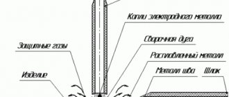
Electrode release
Distance from the torch nozzle to the end of the welding wire. As output increases, gas protection of the welding zone deteriorates. With a small output, the welding technique becomes more complicated, especially corner and T-joints.
Reach and release depend on the diameter of the electrode wire:
| Wire diameter, mm | 0,5-0,8 | 1-1,4 | 1,6-2 | 2,5-3 |
| Electrode extension, mm | 7-10 | 8-15 | 15-25 | 18-30 |
| Electrode outlet, mm | 7-10 | 7-14 | 14-20 | 16-20 |
| Gas consumption, l/min | 5-8 | 8-16 | 15-20 | 20-30 |
The optimal set of mode parameters makes the process stable at three stages:
1 - when the arc is ignited and the welding operating mode is established; 2 - in a wide range of operating modes; 3 - during the completion of welding.
The welding process is considered stable if its electrical and thermal characteristics do not change over time or change according to a specific program. In this regard, mechanized welding in shielding gases is carried out with a stationary arc, pulse-arc method, with a synergetic control system.
What is the difference between DC and AC electrodes?
The differences between DC and AC electrodes can be briefly explained by two statements:
- Welding materials designed for alternating current are also successfully used for welding with direct current. Therefore, experts often call such electrodes universal. More about them below.
- While DC electrodes are generally not suitable for AC welding.
However, it should be remembered that materials of the second group guarantee a better connection . When performing important work, this fact comes to the fore.
What are universal electrodes
Universal welding materials are
DC and AC electrodes. That is, those consumables that work equally effectively on both alternating and direct voltage. This category of welding materials has several advantages:
- good and stable arc;
- increased work productivity;
- fairly high efficiency;
- low level of splashing;
- good slag separation;
- the ability to weld surfaces that are uncleaned from contaminants, oxidized, wet and damaged by corrosion;
- minimum requirements for equipment and welder.
More information about choosing current for electrode welding in practice
Recommendations from experienced welders will help you find the optimal value.
Influence of welding mode
The parameters that regulate the process are divided into basic and additional. The first group includes:
- speed of movement of the consumable;
- its diameter;
- arc voltage;
- type, polarity and current.
We recommend reading: How to get a NAKS certificate
Arc voltage, polarity and current control the welding process.
Additional options are:
- position of the consumable;
- composition and thickness of its coating;
- part orientation.
All of these factors are called welding mode. They are interconnected: a change in one value entails a correction in the other. For example, if you need to reduce heat input, you can do it in 2 ways:
- Reduce amperage.
- Increase the speed of movement of the consumable.
This relationship is taken into account and, if necessary, productivity is increased. Set the speed to a higher speed while simultaneously increasing the amperage.
It is impossible to evaluate the influence of each factor mathematically and derive the corresponding formulas. In each case, it is important to adapt and select the optimal amperage experimentally.
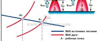
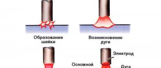
Arc length
There is a linear relationship between arc length and arc voltage. As the first indicator increases, so does the second. In this case, the current strength and heat generation change little.
Arc length affects voltage.
As the length of the arc increases, the quality of the seam decreases. The reasons are as follows:
- The discharge “walks” along the surface, as a result of which heat spreads over a large area. Accordingly, the edges in the joint zone warm up worse.
- The molten metal from the consumable rod bounces off the poorly heated surface. Spattering increases and the seam becomes dirty. Only part of the alloying elements enters the weld pool.
The optimal arc length in mm is determined by the formula L=d+0.5, where d is the electrode diameter in mm.
The melting consumable is gradually shortened during operation, so the holder is gradually brought closer to the workpiece.
Forward or reverse polarity
When welding with direct current in an arc, 2 zones are distinguished:
- Anode spot. Located on the positive pole side of the source.
- Cathode. It is located on the minus side.
The zones have different temperatures. When using a consumable electrode, the anode spot is colder than the cathode spot, so to connect thin-walled workpieces proceed as follows:
- “Plus” is connected to the part being welded (straight polarity).
- Set the minimum current from the recommended range.
In the argon arc method, direct polarity is used.
This prevents burning of the workpieces.
To connect thick-walled parts, strong heating is required. For this:
- A “minus” is connected to them (reverse polarity when welding).
- Set the maximum amperage from the proposed range.
This ensures deep penetration, making the connection strong and reliable.
When using a refractory electrode (argon-arc method), an inverse temperature distribution is observed: the anode spot is hotter. This technology provides only direct polarity, since in reverse the arc hits the consumable and it quickly becomes clogged. When connecting thin-walled parts, heat input is controlled by amperage and welding speed.
Electrode coating
Based on their composition, there are 4 types of coating:
- Rutile.
- Main.
- Cellulose.
- Sour.
The electrode coating can be rutile.
The main coating differs from the others in the presence of a deionizing element - fluorine. It reduces the number of charge carriers, which makes arcing more difficult. To stabilize this process, it is necessary to increase the amperage by 20-30 A. So, if for welding with a rutile consumable with a diameter of 2 mm, the device is set to 40-70 A, then for the main consumable of the same thickness - to 60-100 A.
Direct and alternating current
The type of current does not affect the amperage. It is selected according to the following criteria:
- If high demands are placed on the quality and strength of the seam, constant tension is used. It is characterized by slight arc deflection and weak metal spattering. The seam turns out smooth and clean. On direct current, the arc burns better; it is possible to regulate the temperature distribution by changing the polarity. This is used when working with thin-walled workpieces and non-ferrous metals.
- If the requirements for the quality and strength of the connection are low, alternating voltage is used. It allows you to reduce costs, because equipment for this type of welding costs 1.5 times less. It is also smaller in size and weight.
We recommend reading Samples of technological map for welding work
In addition, preference is given to alternating current in the following cases:
- The workpiece material contains oxides. Frequent changes in the direction of current contribute to their greater destruction. For example, aluminum is welded using alternating voltage, because an oxide film forms on its surface.
- The surface of the part is so dirty that it cannot be cleaned.
With constant current, the seam is smooth.
When choosing the type of voltage, the coating material of the consumable is also taken into account. On electrodes with a basic coating, the arc burns worse due to the deionizing effect of fluorine, so they can only be welded with direct current. For other varieties, any genus is suitable.
Features for inverters
The main difference between devices of this type is the presence of a special electronic unit that increases the frequency of the mains current to tens of kHz. This gives the following result:
- The size and weight of the transformer are reduced.
- Its efficiency increases.
- The price is reduced (due to reduced material consumption).
Electronic control makes it easy to adjust the current strength. It is set by a switch on the inverter, and the device selects the voltage automatically. Models with smooth adjustment are the most convenient to use.
The electronics independently adjusts the amperage when:
- Arc ignition. The function is called “Hot Start” or Hot Start. The current briefly increases by 5-100% of the rated current, which facilitates the occurrence of an arc discharge. On cheap models, the manufacturer sets the excess value at its discretion, and it cannot be changed. On expensive ones, the parameter is set by the user. The function is in demand when welding with poor consumables, the presence of rust and scale on parts, and unstable voltage in the network.
- Breaking the arc or connecting the electrode to the workpiece using a drop of molten metal (the consumable is welded). A surge of current also occurs. This promotes the resumption of discharge combustion or the separation of a drop from the rod. The function is called Arc Force.
- Touching the workpiece with the rod. The amperage is reset, which allows you to tear off the consumable. The name of the function is “Antistick”.
The required mode for welding with an inverter is selected taking into account its power. Many models belong to the household class and are not designed for high currents. The maximum diameter of the consumable for them often does not exceed 2 mm, the recommended amperage is 30-45 A.
What is the difference between constant welding and variable welding?
Advantages of constant voltage welding:
| Advantages of AC welding:
|
Flaws:
| Flaws:
|
Conclusion: why it is important to determine the strength of the welding current
If you work with a welding machine without an automatic mode, you will have to learn how to determine the strength of currents. By changing it, it is possible to make the seam stronger and thicker, depending on the purpose. Errors do happen in practice, and that's normal. But, if you don’t want to learn from them, it’s enough to use the tables that we outlined in the review. Save them and use them when necessary. After a while, you will be able to adjust the inverter without errors, which will simplify the welding process.
Popular brands of electrodes for AC and DC current
1. MP-3S electrodes are the most popular universal type materials. Advantages: easy ignition of the arc both during the first and subsequent ignitions; rutile coating protects the seam from rapid oxidation and from slag inclusions; high level of arc constancy. [ads-pc-3][ads-mob-3]
2. ANO-37 are intended for welding and repair work on structures made of carbon and low-alloy steels. Advantages: insensitive to the presence of dirt and rust; fairly wide gaps are well closed by consumables of this brand; easy arc ignition; the seam is perfectly formed even at low welding voltage values; well suited for a novice welder (even a beginner can make a high-quality product).
3. OK 46.00 are used for structural and carbon steels. Pros: easy ignition; suitable for welding wide gaps, insensitive to rusty and dirty surfaces; minimum amount of splashes; welding is carried out in all spatial positions.
4. OZS-4 electrodes are used for working with carbon steels. Advantages: not susceptible to metal that is poorly cleaned of dirt, rust and moisture; easy arc ignitability; possibility of welding at high conditions; products of medium and large thicknesses are successfully welded by this brand.
5. One of the most popular imported brands of universal consumables is LB-52U. The demand for Japanese-made welding materials is due to several reasons: high level of productivity; minimal splashing; excellent mechanical properties; Arc stability is maintained in low and high voltage modes.
6. ANO-4 are used for welding critical structures made of carbon steels. Advantages: welding of wet, rusty or poorly cleaned metal is allowed; easy arc ignition and stable combustion; slight tendency to form pores; welds are of high quality; insensitive to changes in arc length.
[ads-pc-4][ads-mob-4]
Welding safety
The regulations establish the following rules:
- The welder puts on a special suit, gloves made of spark-resistant material, and closed shoes with rubber soles. They protect the skin from splashes of molten metal and harsh ultraviolet radiation from the arc. The face is covered with a mask with dark glass. Eyes must be protected not only from direct ultraviolet rays, but also from side glare (reflections from walls).
- The post is equipped with a hood. If work is carried out in the field or installation conditions, ventilation will be organized. If this is not possible, the welder works in a respirator. Electrodes with an acidic coating are the most toxic. Instead, it is recommended to use rutile acid.
- If there are people near the post, the master loudly pronounces the word “eyes” immediately before lighting the arc. So he warns them about the need to turn away or protect their eyesight.
- When performing work at height, use a mounting belt and other safety equipment.
- Comply with electrical safety requirements.
The last item includes the following settings:
- Before starting work, check the integrity of the insulation of cables and other live parts. If there are ruptures, crumbled areas and other defects, it is prohibited to use the device.
- If it is necessary to repair, replace consumables, move, or during downtime or a lunch break, the equipment is de-energized.
- The connection to the network is made through a circuit breaker that protects against short circuits.
- Welding in conditions of high humidity (in a boiler room, cooling tower, basement or outdoors during rain) should be carried out by a welder with the appropriate skills.
The welder puts on gloves and a special suit.
Welding current symbols for electrodes, voltage and polarity
AC and DC current, any polarity
AC and DC current, reverse polarity (positive on electrode)
Alternating and direct current, straight polarity (minus on the electrode)
Direct current, reverse polarity (positive on electrode)
Direct current of any polarity