MINISTRY OF ENERGY AND ELECTRIFICATION OF THE USSR
MAIN PRODUCTION AND TECHNICAL CONSTRUCTION DIRECTORATE
ALL-UNION INSTITUTE FOR DESIGNING ORGANIZATION OF ENERGY CONSTRUCTION "ORGENERGOSTROY"
TECHNOLOGICAL MAPS FOR THE CONSTRUCTION OF OHL 35 - 750 kV
STANDARD TECHNOLOGICAL CARDS
(COLLECTION)
K-V-19
CRIMPING OF ALUMINUM STEEL CABLES WITH A SECTION OF 120 - 700 mm2 AND LIGHTNING PROTECTION CABLES WITH A SECTION OF 50 - 70 mm2
Moscow
1975
The collection of technological maps K-V-19 was prepared by the department of organization and mechanization of the construction of power lines of the Orgenergostroy Institute.
Compiled by: B.I. RAVIN, E.N. KOGAN, A.V. TSITOVICH, N.V. BALANOV, N.I. BALABANOVA, A.A. KUZIN, V.A. POLUBKOV, E.N. SOROKINA
Collection K-V-19 consists of eight standard technological maps for connecting steel-aluminum wires with a cross-section of 120 - 185 mm2 by twisting, for installing pressed clamps on steel-aluminum wires with a cross-section of 240 - 700 mm2 and steel cables with a cross-section of 50 - 70 mm2, as well as for thermite welding wires in anchor cables.
The maps were compiled in accordance with the guidelines for the development of standard technological maps in construction, approved by the USSR State Construction Committee on July 2, 1964.
With the release of this collection, the collection of standard technological maps K-V-8 is canceled. (OM-152031, 1965 edition).
| TYPICAL TECHNOLOGICAL CARD | Overhead line 35 - 750 kV |
CRIMPING OF GROUNDING CLAMPS ON STEEL LIGHTNING PROTECTION CABLES WITH SECTION 50 - 70 mm2
K-V-19-7I. SCOPE OF APPLICATION
Technological map K-V-19-7 is a guide for crimping grounding clamps of the ZPS type on steel lightning protection cables with a cross-section of 50 - 70 mm2 and serves as a guide when drawing up projects for work on overhead lines with lightning protection cables of these sections.
II. TECHNICAL AND ECONOMIC INDICATORS FOR ONE CLAMP
| Indicators | Steel cables cross section, mm2 | |
| 50 | 70 | |
| Installation of ZPS type grounding clamps using a PO-100 M motor press: | ||
| labor intensity, man-hour. | 0,37 | 0,45 |
| work of mechanisms, machine hours. | 0,1 | 0,11 |
| gasoline consumption, kg | 0,14 | 0,15 |
| Installation of grounding clamps type ZPS using a manual press MI-1B | ||
| labor intensity, man-hour. | 0,52 | 0,63 |
| Unit productivity per shift (8.2 hours) number of pressed grounding clamps: | ||
| motor press | 43 | 37 |
| by hand press | 31,5 | 26 |
III. ORGANIZATION AND TECHNOLOGY OF WORK
1. Work on crimping grounding clamps (Fig.) is carried out during the installation of lightning protection cables on overhead power lines by a team of electric linemen consisting of:
| Item No. | Worker's profession | Discharge | Number of people | Note |
| 1. | Lineman | IV | 1 | |
| 2. | -«- | III | 1 | |
| Total | 2 people |
2. Sequence and methods of performing basic operations (Fig.):
a) straighten the end of the cable, apply bandage “B” and cut it evenly;
b) clean the end of the cable with a length l = 100 mm from dirt and grease with a rag soaked in gasoline, wipe dry and cover with a thin layer of technical petroleum jelly;
c) push the grounding clamp, prepared in accordance with paragraph “General Part,” onto the end of the cable until it stops;
d) press the clamp in the direction shown in Fig. .
3. The crimped clamp should be inspected and the diameter measured. If the diameter does not meet the standard, the clamp should be pressed back to the standard.
4. A journal is compiled for the crimped clamps in the prescribed form.
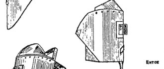
Clamp before crimping
| Standard size | Cable brand | Matrix | Dimensions, mm | |||||
| Designation | Sectional area, mm2 | Diameter, mm | L | ldef. | D | A | d | |
| ZPS-50-1 | S-50 | 49,49 | 19 | 108 | 50 | 22 | 18 | 9,5 |
| ZPS-70-1 | S-70 | 72,58 | 24 | 180 | 60 | 28 | 23 | 11,5 |
Rice. 1 ZPS type grounding clamps for steel cables
Preparing the end of the lightning protection cable before crimping
Clamp crimping
1. The nominal diameters of the dies for various types of clamps are shown in the table in Fig.
2. Tolerance on matrices - (dн + 0.2) mm
3. Tolerance for the pressed part of the clamp - (dн + 0.3) mm
Rice. 2 Crimping of the ZPS brand grounding clamp
IV. ORGANIZATION AND METHODS OF WORKERS
1. Work on crimping grounding clamps of the ZPS type on steel lightning protection cables with a cross-section of 50 - 70 mm is carried out by specially trained electric linemen of IV and III categories from the installation team engaged in the installation of wires and lightning protection cables on overhead power lines.
2. Crimping of grounding clamps on lightning protection cables is carried out using a PO-100M crimping unit or a manual hydraulic press in the sequence specified in Section III.
V. CALCULATION OF LABOR COSTS
| Base | Name | Scope of work | Labor costs during crimping, man-hour. | |
| Motor press | By hand press | |||
| 1 | 2 | 3 | 4 | 5 |
| Those. calculation standards | Preparation and crimping of ZPS type grounding clamps on lightning protection cables with the following cross-section: | |||
| 50 mm2 | One clamp | 0,37 | 0,52 | |
| 70 mm2 | -«- | 0,45 | 0,68 | |
VI. MATERIAL AND TECHNICAL RESOURCES (for one level of workers)
1. Mechanisms
| Name | Type | Brand | Qty, pcs. | Note |
| Crimping unit motor | Trailed | PO-100M | 1 | |
| or hand press | MI-1B | 1 |
2. Tools, devices, materials
| Item No. | Name | Unit change | Qty. | Note |
| 1. | Machine for cutting leads and cables | PC. | 1 | |
| 2. | Matrices for the press | set | 2 | Selected according to the type of pressed clamp (see fig.) |
| 3. | Steel meter | PC. | 2 | |
| 4. | Steel tape measure | PC. | 1 | |
| 5. | Hacksaws for metal | PC. | 2 | |
| 6. | Hacksaw blades | PC. | 20 | |
| 7. | Calipers | PC. | 2 | |
| 8. | Bench chisel | PC. | 1 | |
| 9. | Universal pliers 250 mm long | PC. | 2 | |
| 10. | Bench hammer 0.5 kg | PC. | 1 | |
| 11. | Wire cutters | PC. | 1 | |
| 12. | Steel brushes | PC. | 2 | |
| 13. | Card brushes | PC. | 2 | |
| 14. | Screwdrivers | PC. | 2 | |
| 15. | Personal file 300 mm long | PC. | 1 | |
| 16. | Flat hog file, 300 mm long | PC. | 1 | |
| 17. | Soft knitting wire | kg | 1 | |
| 18. | Gasoline (or other solvent) | kg | 5 | |
| 19. | Rags | kg | 2 | |
| 20. | Neutral technical Vaseline (GOST 782-59) or ZES lubricant (MRTU 28-1-206-66) | kg | 0,5 |
3. Operating materials
| Item No. | Name | Norm for 1 hour of work (average), kg | Note |
| 1. | Gasoline for crimping unit PO-100M | 1,4 | See technical and economic indicators for each clamp |
Instructions for installing clamps
As mentioned above, clamps are widely used for creating loops and splicing cables. When carrying out such work, it is necessary to comply with technological standards, since incorrect installation can reduce the maximum operating load of the backbone node by 40%.
First you need to make sure that:
- The product has no nicks, dents or cracks.
- The size of the product corresponds to the size of the cable.
Traditional clamps
Step one. The first fastener element is located at a short distance from the free end of the loop. The nuts or bolts are tightened one at a time until the required torque is achieved.
Step two. The second is placed closer to the loop, so that it has a minimum course of deformation. The stroke can be checked by flattening the loop towards the clamp after installation.
Step three. The third is positioned exactly between the first two. It is taken into account that the mating parts of the clamps (those from which the nuts or bolts are tightened) should be directed upward.
Step four. A load equal to or greater than the required one is applied to a section of the main line. The tightness of nuts or bolts is checked and, if necessary, increased.
When splicing, the algorithm for installing the clamps will be the same.
Flat – Simplex and Duplex
They are used in the same cases as traditional ones, but have a different design. Let's look at their installation below using DUPLEX as an example.
Step one. Make sure that the product is complete, the parts are in good condition, and the nuts are not tight on the threads.
Step two. When creating a loop, place the product closer to its beginning; when creating a loop or splicing, position the cable inside the clamp as shown in the figure.
Step three. Install the mating part and tighten with nuts. Apply a load on the structure equal to or greater than required. Check the tightness of the nuts and increase them if necessary.
SIMPLEX Clamp Installation
Installing the DUPLEX Clamp
Special clamps
In relation to special types of clamps, it is impossible to give a general algorithm of actions, however, since it is not possible to position them except for their intended purpose, tightly tightening the fasteners solves the issue of their reliable installation.
EXTRACT from Safety Rules for the construction of overhead power lines
Chapter III - Construction of power transmission lines with voltage of 35 kV and higher.
Section 16 - installation of wires and lightning protection cables.
GENERAL INSTRUCTIONS
16.1. It is prohibited to stand under garlands of insulators, mounting blocks, wires, cables and other objects during lifting, as well as to be or pass under the thermite welding site.
16.2. When installing and dismantling longer overhead lines, the wires of individual mounted sections 3 to 5 km long must be short-circuited and grounded.
16.3. Grounding conductors are first connected to the ground, and then to wires and cables.
16.4. When a thunderstorm approaches and during a thunderstorm, work on installing wires and cables, as well as the presence of people near the supports, is prohibited.
CONNECTION OF WIRES AND CABLES
16.20. Wires and cables should only be cut using an appropriate tool (hacksaw, cable cutter). It is prohibited to cut wires and cables with a chisel.
16.21. Do not use leaded gasoline to wash the ends of wires and connecting clamps.
16.22. After crimping the drives and cables, be sure to file away any burrs formed on the connecting or tension clamp.
THERMITE WELDING OF WIRE
16.23. Thermite welding of wires must be carried out in accordance with the “Instructions for thermite welding of overhead power line wires” approved by Soyuzglavenergo.
16.24. Persons trained in welding techniques and who can perform welding independently may be allowed to work on thermite welding of wires.
16.25. Thermite welding should be done with dark safety glasses. During welding, the person working must be at a distance of at least 0.5 m from the welding site.
16.26. Do not touch or handle a burning thermite cartridge with your hand. Burnt and cooled slag should be knocked away from you and only after it has completely cooled.
16.27. When performing thermite welding work on wooden supports or portals in hot and dry weather, all measures should be taken to prevent fire of the portal support or dry grass from accidental contact with uncooled slag.
16.28. An unburned thermite match should be thrown onto a pre-designated earthen area or into a metal box, near which there should be no flammable objects.
16.29. When rearranging and carrying boxes with thermite cartridges and matches, strong shocks and throws should be avoided.
16.30. Thermite matches should be stored in separate boxes in their original packaging.
16.31. Boxes with thermite cartridges should be stored separately from boxes with thermite matches and stored in stacks on the floor with the lids facing up. The height of the stack should not exceed 2 m.
16.32. Storage for thermite cartridges and matches must be dry, fireproof and meet the established requirements for storage of fire hazardous products; thermite cartridges and matches must be stored in closed metal cabinets.
16.33. Extinguish a thermite cartridge fire only with sand or a foam fire extinguisher. It is prohibited to use water for these purposes.
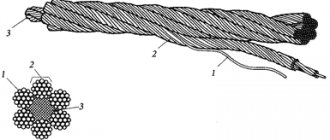
Conclusion
It’s impossible to say unequivocally that braiding or crimping is better. Each of these two methods has its own advantages. When choosing a rope sling, you must take into account the specifics of the job. If you have to work in extremely low temperatures (in northern regions), it is better to give preference to a braided rope sling. For work in temperate climates, when the flexibility of the rope sling along the entire length is not required, and the loading and unloading method does not contain any special requirements, it is more profitable to use slings with aluminum bushings.
If you could not decide on the type of product, qualified managers will help you with your choice.
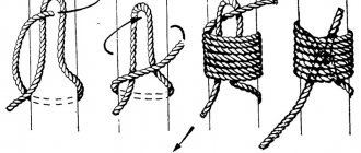
MAGAZINE on the installation of oval connectors using the twisting method
Wire brand __________; Connector drawing no. __________; connector brand ____________. Name of the tool (device) for twisting ___________.
Item no. No. of wires Connector between supports for No. Executive diagram of wire splicing, drawing. No. Number of turns of the connector Date of work performed Name and signature of the artist Name and signature of the craftsman 1 2 3 4 5 6 7 8 1.2.
3.
Layout of wires in the span
| I chain | I. phase _______________________ 1 II. phase ______________________________ 2 III. phase ______________________________ 3 | |
| Note: if there is a cable, the cable log is filled out according to form No. ______ | II chain | I. phase _______________________ 1 II. phase ______________________________ 2 III. phase ______________________________ 3 |
| "__" _______________ 19__ Chief Engineer construction and installation organization __________________ (last name) (signature) | ||
Do-it-yourself cable crimping - Metalworker's Guide
When using metal ropes, it may be necessary to fasten them together or form loops at their ends. A steel cable clamp will help you cope with this task effectively. We will describe below what modifications exist and how to use them.
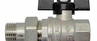
Cable clamp. Types and work. Application and device
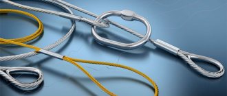
A cable clamp is a rigging element used to fix loops on a steel cable or splice it.
It provides reliable fastening and, according to the requirements of GOST and SNiP, is a mandatory element for construction work that involves steel rope.
Connecting with clamps is more reliable than tying with knots, but worse than intertwining the ends during splicing.
JOURNAL of connection of wires by thermite welding in spans and anchor loops of overhead lines ___________ kV
(name of overhead line)
Welding tool type _____________*
No.: No. of wires according to the diagram Place of welding Thermal welding is performed with a brand chuck Dimensions of the loop on the support, cm Date of work performed Name and signature of the welder Name and signature of the foreman Note In the span between the supports for No. Anchor. support No. To the rack to the traverse 1 2 3 4 5 6 7 8 9 10 11 LAYOUTS OF WELDED LOOPS AND WIRES"__" ____________ 19__ Chief Engineer
construction and installation organization __________________
(signature, surname)
What materials are the clamps made from?
What is your saddle made of, wanderer?
The three main materials from which cable clamps are made are (very predictably!): stainless steel, hot-dip galvanized and zinc coated mild steel. Let's look at the example of a saddle.
Stainless steel A2 and A4. Your choice for outdoor applications and harsh conditions. Corrosion resistant out of the box.
Hot-dip galvanized steel. Feel free to take it if you want to save money. Use in unfavorable environments is limited, but it more than meets the required loads. Corrosion resistance is less than that of stainless steel.
Mild galvanized steel. By cheap means, by cheap. The material is not resistant to corrosion (however, you can’t pick off galvanized steel with your finger). If you need something for everyday life, this is the best option.
However, remember that when building highly loaded structures, you will need to check the attachment point at least once every three months to ensure that it is completely eaten up by rust. Hehe. Joke.
Appendix 6
| Name | Purpose | Weight, kg | Manufacturer or who developed the drawings | Note |
| Wire cutting tool R-1 | For cutting aluminum wires with cross-sections from 50 to 700 mm2 | 1,5 | Dmitrov Electromechanical Plant | |
| Wire cutting machine MI-222 | For cutting steel-aluminum wires. Largest wire diameter 37 mm | 52,0 | Drawings developed by PKB "Glavenergostroymekhanizatsiya" | The electric motor of the machine is commutator, single-phase, universal. Voltage 220 V |
| Portable wire cutting machine SRP-3 | For cutting wires and cables. Wire diameter 10 - 15 mm | 29.0 (without starter) | -«- | |
| Rope cutter MI-148A | For cutting wires and cables. Maximum diameter of cut cable 34 mm | 16,0 | Kyiv Experimental Mechanical Plant |
Mounting accessories for cutting wires and cables
DIY cable crimping
When using metal ropes, it may be necessary to fasten them together or form loops at their ends.
A steel cable clamp will help you cope with this task effectively. We will describe below what modifications exist and how to use them.
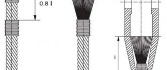
Crimping the wire and lug using improvised means, without a press or special tools
What to do if you don’t have special tools for crimping on hand or you just don’t want to buy them if you only need to crimp one or two tips?
Many, faced with this problem, resort to incorrect methods, which in the future only worsen the contact, without ensuring a reliable connection.