For watering household plots or organizing water supply in a country house, storage tanks are mainly used, the filling of which requires feasible automation. This simplifies the use of irrigation and water supply systems and eliminates the need for visual monitoring of the filling and emptying of the hydraulic accumulator. Considering that the container is usually located quite high, it is very inconvenient to keep an eye on the state of the liquid in the tank. Special sensors for monitoring the filling of the container will cope with this task perfectly.
Types of fill level monitoring products
Liquid level monitoring devices are divided into two main types: contact and non-contact.
Proximity sensors: description
They are used mainly in industrial processes and are divided into ultrasonic devices, capacitive, electrode, operating on the hydrostatic principle, and so on.
Such devices are used not only in water, but also in other environments, including aggressive ones. The circuit includes, in addition to the sensor itself, which is immersed or installed on the walls of the tank, a control controller, which is installed in a separate control unit outside the tank. Such systems are complex and expensive, and, therefore, unprofitable for use in domestic conditions. To control the filling level of the tank with water necessary for irrigation or plumbing, it is more advisable to use simpler and cheaper devices.
Characteristics of contact devices
The most common devices for monitoring the filling of tanks in this type are float-type contact sensors assembled on the basis of reed switches. The devices are simple, reliable and cheap. They are divided according to their location in a container with liquid:
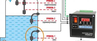
- Vertical arrangement. A rod with a float and a magnet moves along a vertical tube on which the reed switches for turning the pump on and off are located.
- Horizontal placement. Installed in the upper or lower part of the tank wall. As the tank is filled, the float with a magnet attached to it rises on a transverse rod to the reed switch, which switches off the power supply to the pump.
Float sensors for filling control with various design features can be purchased in stores. The choice depends on the specific installation location of the device and operating conditions.
AUTOMATION: PUMPING WATER INTO THE TANK
You have a dacha, for example, like this:
At the dacha there is a well, for example, like this:
There is electricity (of course!) and a 220V, single-phase submersible pump:
There is also a 200 liter tank:
And you want the tank to fill AUTOMATICALLY!
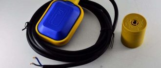
Then, you need to take two more identical compact FineTek float sensors, like these:
and install these sensors on the tank.
so that the pump turns on when there is no or little water in the tank:
But this is not enough for the pump to turn on and off; you also need a PA10-U sensor controller from Autonics. Here he is:
And if your pump is powerful enough, more than 400W, then you will also need a contactor, for example, this one:
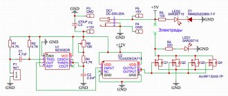
Well, perhaps that's all. Now comes the fun part - connecting! Here's the diagram:
In general, nothing complicated. Considering that you have a summer house, a well, a pump and a tank, and you have the wisdom to purchase everything else, you will probably have the ingenuity to make the correct connection.
The position of the switches on the front panel of the controller should be as follows:
Order technical manuals for sensors and devices from us, as well as the sensors and devices themselves.
Connect and enjoy the automated tank filling process. And enjoy your holiday!
We simply give you the opportunity to know more so that you become the best among professionals!
Review of other news releases:
Selection and supply of automation equipment
Source
Recommendations for making the right choice
The selection of a container fill control sensor depends on a large number of factors:
- Composition of the liquid. It is important to know the amount of foreign impurities in the water. Impurities can change the density and electrical conductivity of the liquid, which will lead to inaccurate readings from a conventional sensor.
- Capacity and material for making the tank.
- Functional purpose of the vessel for generating liquid.
- Type of control. It is important to monitor the maximum and minimum filling levels of the container.
- Possibility of connecting the device to an automated general control system of the “Smart Home” type.
- Switching characteristics of the device.
There are many more criteria for selecting this sensor. But they are most likely not useful for domestic use. Selection parameters can be significantly reduced by focusing on the following parameters:
- Tank capacity.
- Trigger method.
- Control circuit.
A significant reduction in selection criteria allows you to select a sensor in a store at a fairly low price. It also makes it possible to make the device with your own hands without loss in response quality and safety of use.
Electrical part
The station motor is powered directly from the electric meter through a circuit breaker.
To protect the pump, quickly de-energize the engine in cases of unstable power supply or rotor overload, it is advisable to select a machine 10% more than the rated power. For the station motor used in the example, the rated power is 0.77 kW, taking into account the requirements, you need to use a 3.85 A circuit breaker ((770 W + 77 W) / 220 V), but the closest parameter is 5 A. You can use a circuit breaker with differential control.
As practice shows, conventional circuit breakers with similar current parameters cope with their functions quite well.
Self-manufacturing of the sensor
Suppose the task is to automate the use of a “Malysh” type pump to provide water to a summer house or country house. As a rule, water is pumped into a storage tank, and it is necessary to ensure timely, automatic shutdown of the pump when the tank is sufficiently filled. There is no need to install complex and expensive sensors for this. You can make a device based on a reed switch that will perfectly perform the task with your own hands. Let's call this device: an electric float valve for the water level in a tank based on a reed switch.
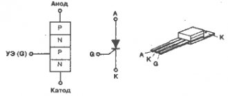
Reed switch
A reed switch is a switch that is the main performing part in the device of a reed switch water level sensor for controlling a pump. It looks like a small sealed glass container with a vacuum or inert gas inside. Inside there is a closed or open contact group, in other words, two closed or open contacts made of ferromagnetic material with a gold or silver top coating. When exposed to a magnetic field, the contacts of the part are magnetized and repel each other, opening the circuit in which they are connected, stopping its operation, or, conversely, they close and turn on the circuit. Reed switches are divided into two types:
- Reed switch with normally closed contacts.
- Reed switch with normally open contacts.
The environment inside the glass bulb prevents oxidation of contacts and the formation of sparks when shorted.
Sensor device based on a reed switch
To manufacture the device, you will need a 220-volt magnetic coil starter and a pair of reed switches, one of which is closed in the normal state, and the second is open. And you will also need a float for the water tank, which is made of foam plastic, a rod, a tube and three wires of small cross-section and thickness.
The operation of the device is simple and, most importantly, safe. The operating principle is as follows:
- In the process of collecting liquid, the float with a magnet, having reached the maximum level of the reed switch, which is in a closed state, opens under the influence of the magnetic field, commutating the power triggering coil, which turns off the pump.
- As the water from the reservoir decreases, the float lowers and when it reaches the lower reed switch, which is triggered by a short circuit under the influence of a magnetic field, the starting coil is switched to start the pump.
- A sensor made according to this principle can operate for many years without complaints, unlike electronic control systems for monitoring the filling of containers. Making a float water level sensor with your own hands is not difficult, and it does not require any special knowledge in the field of electrical engineering.
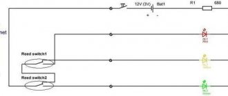
Scheme for controlling water pumping by a drainage pump
Based on the principle of vertical operation of the float mechanism, it is possible to propose a sensor connection diagram for switching the drain pump start relay with an additional 12 volt power supply.
It is worth noting that reed switches are not capable of handling high currents and cannot turn the pump on or off directly. Therefore, they are used in low voltage circuits to switch high-power relays to start or stop a pump. When the level is high, liquid is pumped out until the minimum set level is reached. The operating principle is as follows:
- When the liquid in the container rises to the upper level, the float with a magnet closes the upper reed switch SV 1, and current begins to flow to the relay coil P1. The contacts close in parallel with the connected reed switch, which puts the relay into a self-capturing state. This function does not allow the coil supply voltage to be switched off when the reed switch SV 1 is opened. This is achieved by connecting the relay load and its coil in one circuit.
- The power coil of relay P2 in the electric pump power circuit is switched on and liquid pumping begins.
- When the liquid level decreases, the float with a magnet reaches the lower reed switch SV 2, closing its contacts. A positive voltage potential begins to be supplied to the relay coil P1 from the other side as well. This leads to the removal of the self-capture function and the relay being turned off, which switches off the power coil P2, which provides power to the electric pump.
- By swapping the reed switches SV 1 and SV 2, the sensor will turn off the pump when the container is filled to the set level and turn it on when the liquid level drops.
Scheme of water supply for a house with a storage tank
The presented scheme can be easily integrated into existing piping, both in water supply with one central pipeline and with several. Its compactness is due to the use of free space above the tank, in which the pumping station is suspended on brackets.
Picture 1.
Figure 1 shows a water supply diagram for a private house with two central pipelines consisting of:
- 1 - tank 500 liters;
- 2 - pump;
- 3 — receiver (membrane tank);
- 4 - pressure switch;
- 5 — bronze five-point adapter;
- 6, 17 — pressure gauge;
- 7 — hose with reinforcing braid;
- 8 - check valve;
- 9 — float valve;
- 10 - American with external thread;
- 11 — American with internal thread;
- 12 - bronze transition from the container to the external thread;
- 13, 14 — MRN (male thread coupling);
- 15 — МРВ (internal thread coupling);
- 16 - bronze transition from external thread to internal thread;
- 18 — flow meter;
- 19 — mesh filter;
- 20 - 26 shut-off valves.
The suction discharge and distribution line is made of polypropylene pipeline and transitions with diameters of 32 mm (suction) and 20 mm.
Inexpensive industrial devices
There are also inexpensive models of liquid level control sensors, which can be purchased in stores for about 2 thousand rubles
Various modifications of ARS
Such float sensors are usually used in reservoirs. The measuring head in devices of this type is small, which makes the device compact. The load capacity, according to the operating instructions, can reach 1 ampere. The wire entry into the devices is sealed. The body is made of plastic. The operating differential is 45 degrees. The maximum pressure for correct operation of devices is 3 bar. The cost is about 2 thousand rubles, depending on the modification.
“Crystal” container filling control devices
These float type sensors can be used in harsh environments. Very compact. The measuring head is 2.3 centimeters in diameter. The maximum pressure for correct operation reaches 3.3 bar. The wire input is made in the form of a plastic seal. The devices are equipped with a spark protection barrier. Can work in hot environments. The price is slightly higher than 2 thousand rubles, depending on the modification.
Burkle devices
These devices are designed for contaminated environments, but can also be used in clean ponds and clean water tanks. The maximum pressure for correct operation is 4.1 bar. The maximum possible load is 1A. It is possible to work in environments heated to 170 degrees, in liquids with a density of up to 3 kg per square meter. cm. The average price of the device is 2,200 rubles and depends on minor modifications made by the manufacturer.
Fine Tek and Wilo sensors
These float type devices can be used in harsh environments. They are used for drainage purposes and can also be installed in wells. The sensors can withstand loads up to 2 amperes. The measuring heads are compact and measure 2.5 cm. The wire inputs are made in a specialized seal. The cases are made of heat-resistant plastic. The devices are equipped with fuel probes, which allows their use in flammable environments. The price ranges from 2 thousand to 2500 rubles and also depends on the modification.
Wilo float-type devices are the cheapest, but are not functionally designed for aggressive environments and can only be used in clean water. The sensors have small measuring heads and are compact in appearance. The maximum temperature of use is 140 degrees. The operating differential is only 30 degrees. The maximum operating pressure does not exceed 2 bar. The price of such sensors fluctuates around 1900 rubles.
Tank and pumping station
A plastic cylindrical tank with a volume of 0.5 m3, a cross-section of 640 mm and a height of 1840 mm, with a wall thickness of 5 mm, is used as a storage tank.
The pumping station consists of:
- JEX 500 pump with low noise emissions, capable of providing system pressure up to 4 bar. When using a noisy unit in an apartment, conflicts with neighbors may arise, even leading to litigation.
- Receiver 24 liters. Significantly reduces water hammer on the pump that occurs during water extraction, and also increases engine life.
- A special bronze five-terminal adapter, with the help of which all components of the station are switched.
- Tubes with reinforcing braiding designed to connect the pump and the membrane tank.
- An automatic unit (pressure switch) for operating the pump in a certain pressure range.
- Pressure gauge. This device is not a mandatory attribute for the station, but based on its readings, you can check the tightness of the circuit and, if necessary, configure the automation unit.
Pumping station.
The ceiling height in the room where the described water supply system is installed is 2.5 m. This distance allows you to install a station with dimensions of 600 X 400 X 400 above the storage tank. To attach it, brackets from air conditioners are used, and a rubber hose with a diameter of 32 mm and a length of 400 mm, cut lengthwise, is used as a vibration pad.
Installation of a surface electric pump
To install a surface electric pump and external stations, it is necessary to make and equip a well. In private and country houses, on summer cottages, it is recommended to make a caisson. It can be metal, plastic, concrete. Such designs differ in shape - round, square or rectangular.
Plastic caissons are considered economical options. They are light in weight and easy to set up and install. But groundwater can lift the material outward, causing the structure to collapse. For a country house, you can buy concrete caissons, which are made of individual rings. This material allows water to pass through, so there will be moisture inside the structure.
The best option is to use metal, but it is expensive and requires costs for arrangement and installation. Inside the caisson there is water intake equipment, a hydraulic accumulator, and a pump. In surface pumps, the intake depth is no more than 9 m. To connect surface equipment, a deep and large hole is needed.
Installation diagram of a surface electric pump.
The suction pipe can increase the level of water pressure in the system and protect the components. It is lowered 1 m. After installation, connections are made, the functionality of the equipment is checked and errors are eliminated.
What is well automation?
The automation unit for submersible or surface pumps is a modern electronics unit that includes a hydraulic accumulator, modules and a pressure gauge. All of them guarantee the correct operation of the highway.
Automation functions for water pumps:
- Control. All processes are carried out automatically, without control or supervision.
- Protection against water hammer. A water reserve is created in the main line in case of equipment malfunction or breakdown.
- Electronic devices are triggered in the absence of a liquid medium and turn off the electric current.
Automation for a water supply pump without a hydraulic accumulator helps prevent equipment breakdown and premature failure.
Automation device for a well.
Emergency overflow and drain
To protect against flooding of the room in cases of overfilling of the container, an emergency overflow is installed in its upper part, consisting of:
- transition with a diameter of 1 inch;
- corrugated hose with a cross section of 32 mm;
- siphon for washing;
- fastenings for sewer pipe 50 mm.
A tee with a 45-degree outlet was installed into the existing sewer system. The outlet pipe of the siphon is connected to the tee through a rubber transition from a diameter of 32 mm to a cross-section of 50 mm. For reliability, these components are treated with silicone sealant.
When it is not possible to supply liquid by the pump (breakdown, no electrical power), the water is drained through an emergency drain located in front of the suction line check valve.
In this case, the drain valve 26 is placed as close to the bottom as possible.
Basic operating rules
After putting the station into operation, it is necessary to carry out regular preventive inspections. If necessary, wash the filters and tighten the threaded joints. If the filters become clogged, water begins to flow into the network in pulsating jerks, and sometimes stops flowing altogether. The frequency of filter washing depends on the quality of the water in the well.
The hydraulic accumulator should also be inspected approximately once a month. If the pressure reading in its air chamber is below the required level, then it should be raised using a car pump through the nipple. For proper operation and maintenance of the device, you need to carefully read the diagram of the pumping station and the manufacturer’s recommendations, usually indicated in the technical instructions.
Leak search
The device is not sealed due to:
- wear of the sealing gasket of the toilet tank;
- damage to the rubber or ceramic seal of the mixer, shut-off valves;
- the presence of cracks in the membrane or a malfunction in the spool-type valve of the receiver;
- use of defective components;
- violations of assembly technology.
Signs of a leak in the system:
- there is no water extraction, and the pump turns on periodically;
- when the device is de-energized, the station pressure gauge shows a decrease in pressure down to 0 bar.
If the above symptoms appear in the wiring, you must:
- Disconnect power to the pumping station.
- Close valves 23, 24.
- Monitor the readings of pressure gauge 6; if they change, it means that the leak is in the fittings of the pump, the suction line, the discharge pipeline to the specified valves, or in the receiver.
- If the pressure is unchanged, open the supply valve (23 or 24) and monitor the pressure gauge values. If a leak is detected, we examine the system components from the shut-off valves to the last element of the water supply system. We check the second tap using the same system. Any identified leaking components must be reviewed or replaced. In the place where the pipes are located (if they are hidden in the screed), it is difficult to determine the leak, since, usually, materials are laid on the floor that repel or poorly absorb water: tiles, linoleum, laminate, etc. Therefore, in such places when installing a water supply system In a private house, it is better to lay solid pipes and avoid joints.