A standard heating system includes many elements. Each of them performs its own task, as a result of which the design works smoothly and accurately. One of these elements is a heating check valve that controls the flow of coolant.
We will introduce all types of check valves used today in the organization of heating circuits. The article we presented describes their design features in detail and provides technical characteristics. Do-it-yourselfers will find installation manuals and valuable advice here.
Why is a check valve needed?
During operation, hydraulic pressure appears inside the heating system, which may be different in different areas. The reasons for this phenomenon are very different.
Most often, this is uneven cooling of the coolant, errors in the design and assembly of the system, or its breakthrough. The result is always the same: the direction of the main fluid flow changes and it turns in the opposite direction.
This is fraught with very serious consequences, including the failure of the boiler, or even the entire system, which will require significant repair costs in the future.
For this reason, experts strongly recommend installing a check valve. The device is capable of passing liquid in only one direction. When reverse flow occurs, the locking mechanism is activated and the hole becomes impassable for the coolant.
Thus, the device is able to control the flow of liquid, passing it in only one direction.
The principle of operation of the check valve is very simple. It passes the coolant fluid in a given direction and blocks the path when it tries to move in the opposite direction
For normal operation of the system, it is necessary that the device does not create additional pressure and freely passes the coolant moving to the radiators. Therefore, it is extremely important to choose the right product.
Types of check valve
Despite the fact that all devices of this type perform the same task, they have structural and, therefore, operational differences. Let's take a closer look at each of these types.
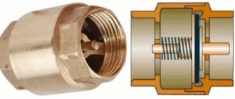
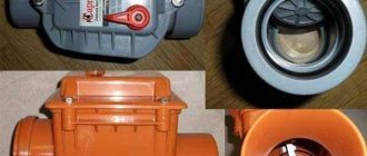
Disc type devices
A distinctive feature of the product is the presence of a disc valve. This is a plastic or metal element, the dimensions of which allow it to completely block the flow of coolant if it begins to move in the opposite direction.
The disk is connected to a steel spring. When a liquid moves forward, it is in a compressed state. When changing direction, it straightens and moves the disk from its place, thereby blocking the pipe.
The valve design also includes a sealing gasket, which allows the valve mechanism to sit as tightly as possible in the seat. Therefore, leakage is excluded in serviceable devices.
Disc devices are widely used in the design of household heating systems, as they have significant advantages:
- Compactness. The dimensions of the products and their weight are small, which makes it possible to install them on any system.
- The device does not require regular maintenance.
- The cost of the device is low.
Among the significant shortcomings, it is worth noting that it is unsuitable for repair. Therefore, failed valves are immediately replaced with new ones.
A significant disadvantage of disk devices is significant hydraulic resistance. The diagram clearly shows how it arises. The liquid has to overcome an obstacle in the form of a locking disc
And one more minus is the significant hydraulic resistance created by the device. For some systems, such as a geothermal heat pump, this can be critical. Over time, the butterfly valve becomes covered with a layer of mineral deposits, which leads to failure of the device.
Standard butterfly valves create some shock loads when closing. This does not affect their performance and technical condition in any way, but water hammer occurs in the system. Which is not desirable for her.
Disk devices with an additional mechanism that allows closing the hole as smoothly as possible do not have this drawback. Their cost is higher than that of standard analogues.
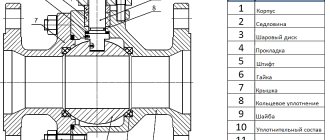
Ball check valves
Devices of this type use a metal ball as a shutter. It is made from aluminum, steel and other metals. To extend the service life, the element is covered with a layer of rubber.
This valve works as follows: when the coolant moves through the body of the device in the desired direction, it lifts the ball, which moves into the upper compartment of the valve.
The ball-type valve has minimal hydraulic resistance, therefore it is widely used in a wide variety of heating systems. Another plus is long service life
As soon as the direction of movement changes or the flow stops, the ball immediately descends and blocks the pipe. Thus, the movement of fluid in the opposite direction becomes impossible.
The advantages of these valves include:
- reliability - the design does not include rubbing or moving systems, which significantly reduces the possibility of breakdown and allows you to work in any position;
- maintainability - the upper part of the valve body is equipped with a removable cover, which provides easy access to the interior of the structure;
- low hydraulic resistance.
Considering the disadvantages, it is worth noting the rather large working diameter. For this reason, it is impossible to use them in domestic pipelines of small cross-sections.
Ball valves are difficult to install due to their design features. When installed horizontally, they must be placed with the lid up, otherwise the shutter will not be able to rise to allow the flow of water to pass through. Based on the same considerations, when installing vertically, you must strictly ensure that the liquid moves strictly upward.
Ball valves will not be able to function normally in pipelines with low pressure. Because the minimum value at which the sphere blocking the passage opening rises is usually 25 bar.
Petal type of shutter
The shutter for this type of valve is a thin steel plate. It is attached to a hinged structure that allows it to move.
The double-leaf type reed check valve is very reliable and can withstand high pressure. But at the same time it exhibits serious hydraulic resistance, since the rotary axis of the valves is located directly in the center of the passage opening
There are two types of petal devices. Single-leaf or rotary are equipped with one plate that can rotate around an axis.
When the coolant moves in a given direction, it lifts the sash, thereby opening the passage hole. When the flow direction changes, the plate lowers. This can be done either with or without a spring.
Butterfly valves are designed slightly differently. They have two locking plates mounted on a rotating axis and located in the center of the passage opening.
The coolant moving along the heating circuit opens both flaps of the double-leaf check valve, and when the direction of its movement changes, the springs slam the plates
The advantages of using these valves are:
- some models of gravity valves can operate without springs, which allows them to be used in gravity systems;
- relatively low cost of devices.
Among the disadvantages, it is worth noting the rather high hydraulic resistance. This is especially true for double-leaf models - the rotary axis is located directly in the center of the passage opening, which is a significant obstacle to moving liquid.
For this reason, butterfly valves are used exclusively in high pressure systems.
Lifting equipment
Lift valves are equipped with a spool that can move freely relative to a vertical axis. On the through hole there is a seat where the spool is located.
When liquid is supplied, the force of its pressure lifts the valve, and it moves along the axis, opening a hole for the movement of coolant. As soon as the flow pressure weakens or it changes its direction, the spool will lower into the seat.
The lift check valve can only be installed vertically. Otherwise, the pressure of the coolant liquid will not be enough to lift the locking mechanism
The advantages of these devices are:
- Reliability. The equipment has a fairly simple design, which allows it to operate with minimal risk of breakdown.
- Low sensitivity to coolant quality.
- Possibility of repairs. For this purpose, a removable cover is located in the upper part of the device body.
Among the disadvantages, installation limitations should be noted. Due to the design features, they can only be mounted in a strictly vertical position.
Water level float switch for pump control
When the need arises to control the fluid level, many do this work manually, but this is extremely ineffective, takes a lot of time and effort, and the consequences of oversight can be very expensive: for example, a flooded apartment or a burnt out pump. This can be easily avoided by using float water level sensors. These are devices that are simple in design and operating principle and are affordable.
- Operating principle of a float sensor
- Equipment classification
- Mechanical devices
- Electrical sensors
- Homemade float switch
- Mechanical system
- Electric type sensor
At home, sensors of this type allow you to automate processes such as:
- monitoring the liquid level in the supply tank;
- pumping groundwater from the cellar;
- turning off the pump when the level in the well falls below the permissible level, and some others.
Operating principle of a float sensor
An object is placed in the liquid and does not sink in it. This could be a piece of wood or foam, a hollow sealed sphere made of plastic or metal, and much more. When the liquid level changes, this object will rise or fall with it. If the float is connected to the actuator, it will act as a water level sensor in the tank.
Equipment classification
Float sensors can independently monitor the liquid level or send a signal to the control circuit. According to this principle, they can be divided into two large groups: mechanical and electrical.
Mechanical devices
Mechanical valves include a wide variety of float valves for the water level in the tank. The principle of their operation is that the float is connected to a lever; when the liquid level changes, the float moves this lever up or down , and it, in turn, acts on the valve, which shuts off (opens) the water supply. Such valves can be seen in toilet flush tanks. They are very convenient to use where you need to constantly add water from the central water supply system.
Mechanical sensors have a number of advantages:
- simplicity of design;
- compactness;
- safety;
- autonomy - do not require any sources of electricity;
- reliability;
- cheapness;
- ease of installation and configuration.
But these sensors have one significant drawback: they can control only one (upper) level, which depends on the installation location, and regulate it, if possible, then within very small limits. On sale, such a valve may be called a “float valve for containers.”
Electrical sensors
An electric liquid level sensor (float) differs from a mechanical one in that it itself does not shut off the water. The float, moving when the amount of liquid changes, affects the electrical contacts that are included in the control circuit. Based on these signals, the automatic control system makes a decision on the need for certain actions. In the simplest case, such a sensor has a float. This float acts on the contact through which the pump is turned on.
Reed switches are most often used as contacts. A reed switch is a sealed glass bulb with contacts inside. Switching of these contacts occurs under the influence of a magnetic field.
Reed switches are miniature in size and can be easily placed inside a thin tube made of non-magnetic material (plastic, aluminum). A float with a magnet moves freely along the tube under the influence of liquid, and when it approaches, the contacts are activated.
This entire system is installed vertically in the tank . By changing the position of the reed switch inside the tube, you can adjust the moment the automation operates.
If you need to monitor the upper level in the tank, then the sensor is installed at the top. As soon as the level drops below the set level, the contact closes and the pump turns on. The water will begin to increase, and when the water level reaches the upper limit, the float will return to its original state and the pump will turn off.
However, in practice such a scheme cannot be used. The fact is that the sensor is triggered by the slightest change in the level, after which the pump turns on, the level rises, and the pump turns off.
If the water flow from the tank is less than the supply, a situation arises when the pump constantly turns on and off, and it quickly overheats and fails.
Therefore, water level sensors for pump control work differently. There are at least two contacts in the container. One is responsible for the upper level; it turns off the pump. The second determines the position of the lower level, upon reaching which the pump turns on.
Thus, the number of starts is significantly reduced, which ensures reliable operation of the entire system. If the level difference is small, then it is convenient to use a tube with two reed switches inside and one float that connects them.
If the difference is more than a meter, two separate sensors are used, installed at the required heights.
Despite their more complex design and the need for a control circuit, electric float sensors allow fully automated liquid level control.
Rules for choosing a locking device
Choosing a check valve intended for a heating system is a responsible undertaking. If knowledge in this area is minimal, it is best to seek help from specialists. This will ensure that your new heating system is functional and safe.
You need to know that, regardless of their type, all check valves differ in the way they are connected to the pipeline.
Sleeve check valves are very easy to install. However, the threaded connection cannot withstand high pressure, so they have limitations in use
Coupling devices are equipped with a connecting threaded unit, which greatly facilitates their connection to the main line. Most often, such a unit is equipped with disc valves intended for installation in autonomous heating systems of an apartment or private house. Their distinguishing feature is their small diameter. Most often it is no larger than DU-50.
Flange products are a structure assembled on the basis of a part that has holes for fastenings. Using the latter, it is connected to the main pipeline. A flange connection is much stronger than a threaded connection.
For this reason, flanged valves are widely used in the construction of large-diameter pipelines. Ball type devices are most in demand.
Wafer devices are designed for installation between two pipe flanges. They are lightweight and compact. Very often, both types of reed-type valves are produced in wafer design.
On sale you can find check valves that are installed by welding. This option can be used, for example, when installing heating from polypropylene pipes.
Flanged type check valves are securely attached to the pipe. This connection can withstand high pressure, which allows the devices to be used in centralized pipelines
Another important selection criterion is the material from which the device is made. It could be stainless steel. This option is considered optimal for highways with a diameter of less than 0.04 m.
The metal is practically not subject to corrosion processes and can withstand loads of up to 10 atm. This allows the valve to operate in the system trouble-free and for a very long time, but its cost is quite high. Brass valves have a lower price. They are subject to corrosion, but this process occurs very slowly, which significantly increases their service life.
However, their mechanical strength is much lower than that of stainless steel. Nevertheless, they can withstand the loads that arise in a household network quite easily. The most durable valves are made of cast iron - they successfully cope with critical pressure values, have significant dimensions and impressive weight.
Due to the nature of production, only body parts with a diameter greater than 40 mm can be made of cast iron. For this reason, they are used extremely rarely for the installation of autonomous heating systems.
It is desirable that not only the body, but also all internal elements of the check valve are made of metal. Plastic usually has less strength, which can lead to premature failure of the part.
When choosing a check valve, you need to remember one more rule - its diameter must exactly match the parameters of the passage hole. It is very important that the operating pressure of the system does not exceed the maximum permissible values for operation established by the manufacturer of the selected model.
Float switch - device, self-replacement
Systems, the functioning and durability of which are determined by the water level and pressure, require the installation of auxiliary elements that make their use automated and safe. The most common among them are float switches and valves, which today have found application not only in industry and agriculture, but also in everyday life. Due to the relevance of this topic, we will consider the features of their structure, operation and installation.
What is a float switch used for?
A float switch is used to start and stop devices whose operation depends on the level of the working fluid in the medium into which the float is lowered. Due to its design, it is capable of solving many problems:
- automatic control of the main and auxiliary water pumping units;
- monitoring liquid levels in case of emergencies;
- overflow alarm;
- protection against dry running and overheating of the motor winding;
- adjusting the sewer filling level.
Options for working connection schemes
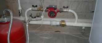
Heating systems are very diverse and the presence of a check valve is not necessary in all of them. Let's consider several cases when its installation is necessary. First of all, a check valve must be installed on each of the individual circuits in a closed circuit, provided that they are equipped with circulation pumps.
Some craftsmen strongly recommend installing a spring-type check valve in front of the inlet pipe of the only circulation pump in a single-circuit system. They motivate their advice by the fact that in this way pumping equipment can be protected from water hammer.
This is in no way true. Firstly, installing a check valve in a single-circuit system is hardly justified. Secondly, it is always installed after the circulation pump, otherwise using the device loses all meaning.
If two or more boilers are included in the heating circuit, the occurrence of parasitic flows is inevitable. Therefore, connecting a check valve is mandatory
For multi-circuit systems, the presence of a reverse-acting shut-off device is vital. For example, when two boilers are used for heating, electric and solid fuel, or any others.
When one of the circulation pumps is turned off, the pressure in the pipeline will inevitably change and a so-called parasitic flow will appear, which will move in a small circle, which can lead to trouble. It is impossible to do without shut-off valves here.
A similar situation arises when using an indirect heating boiler. Especially if the equipment has a separate pump, if there is no buffer tank, hydraulic arrow or distribution comb.
Here, too, there is a high probability of a parasitic flow, to cut off which a check valve is needed, which is used specifically for arranging a branch with a boiler.
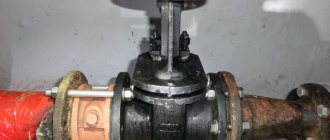
It is mandatory to use shut-off valves in systems with bypass. Such schemes are usually used when converting a scheme from gravitational fluid circulation to forced circulation.
In this case, the valve is placed on the bypass parallel to the circulation pumping equipment. It is assumed that the main mode of operation will be forced. But if the pump is turned off due to lack of electricity or breakdown, the system will automatically switch to natural circulation.
When installing bypass units for heating circuits, the use of check valves is considered mandatory. The figure shows one of the possible bypass connection options
This will happen as follows: the pump stops supplying coolant, the check valve actuator unit ceases to experience pressure and closes.
Then the convection movement of the liquid along the main line resumes. This process will continue until the pump starts working. In addition, experts suggest installing a check valve on the make-up pipeline. This is not necessary, but highly desirable, since it allows you to avoid emptying the heating system for a variety of reasons.
For example, the owner opened a tap on the make-up pipeline to increase the pressure in the system. If, by an unpleasant coincidence, the water supply is cut off at this moment, the coolant will simply squeeze out the remaining cold water and go into the pipeline. As a result, the heating system will be left without liquid, the pressure in it will drop sharply and the boiler will stop.
In the circuits described above, it is important to use the correct valves. To cut off parasitic flows between adjacent circuits, it is advisable to install disk or petal devices. In this case, the hydraulic resistance will be lower in the latter option, which must be taken into account when choosing.
In heating systems with natural coolant circulation, the use of spring check valves is impractical. Only paddle rotators can be installed here
To install a bypass unit, it is preferable to choose a ball valve. This is due to the fact that it provides almost zero resistance. A disc-type valve can be installed on the make-up pipeline. This should be a model designed for fairly high operating pressure.
Therefore, a check valve may not be installed in all heating systems. It is necessarily used when installing bypasses of all types for boilers and radiators, as well as at pipeline branch points.
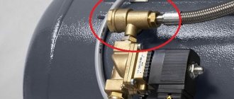
Where are the air release valves located?
In any water heating system there are places where the installation of air vents is mandatory. If we talk about Mayevsky’s taps, then they need to be installed on all batteries in order to bleed off the collected air. The exact location is in the plug of the upper corner, distant from the point of connection of the supply line to the device. An air bubble forms there.
If the boiler is equipped with a built-in air vent, then there is no need to install it on the supply
The automatic air valve must be installed strictly vertically at the following points in the heating network:
- in the safety group of a boiler connected to a closed type system;
- on both underfloor heating collectors;
- if the highest point is a pipeline and not a radiator, then a float air vent cuts into it;
- into a buffer tank and an indirect heating boiler, if provided for by the design;
- on the heated towel rail coil;
- into the common distribution comb of a complex and branched system (to both collectors);
- to the hydraulic circuit separator (hydraulic arrow).
In addition to the indicated points, air vents are installed in problem areas of the heating network, where, due to difficult installation conditions, pipes form U-shaped loops turned upward. For example, a highway goes around a doorway or flight of stairs at the top, and then goes down again. In such compensators, air pockets form with a 100% probability, so an air vent is needed, preferably an automatic one.
When the highest point of the network is a pipe or compensator, a valve is mounted on it
Advice. Never cut the Mayevsky valve directly into the pipeline, since the bubbles will pass by it along with the coolant flow and the valve will be useless. For proper operation, a manual “bleeder” needs a chamber to collect air (the “automatic” has its own). Make a vertical pipe into the main line, which will serve as an air collector, and install a faucet on top.
If, when filling the heating network with water, you do not want to run between the radiators with a screwdriver, install automatic corner air vents instead of Mayevsky valves. This option is also suitable for residents of centrally heated apartments: air pockets often occur in cast iron radiators, and there is no way to remove them from there.
Another tip. To prevent the corner air vent flask from sticking out in plain sight and clinging to the curtains, take a mini-model of the valve built into the radiator cap.
Nuances of proper installation
During the installation of shut-off valves, several rules should be strictly followed:
- The valve is installed strictly in the direction of coolant flow. To avoid mistakes, the product body must be marked with an arrow indicating the working direction.
- Paronite gaskets can be used to seal connections, provided that they do not reduce the diameter of the passage hole. Otherwise, the valve will exert more hydraulic pressure than intended.
- The device must be installed so that other elements of the heating system do not exert additional pressure on its body.
- It is highly advisable to install a mesh in front of the check valve for rough cleaning. This will make it possible to prevent solid particles from entering the locking mechanism, which, in turn, can lead to a violation of the tightness of the device when closed. Or use special valves with mesh.
Another important point: before installation, you need to once again make sure that the valve is selected correctly.
For example, for schemes with forced circulation, any type of device is suitable, but for gravitational systems, only a rotary petal device without a spring. Since the coolant moving by gravity will not be able to cope with the resistance of the spring.