To prevent crystallization of water included in the concrete solution, it is necessary to maintain a certain temperature of the poured mass.
The fact is that the binder (cement) reacts with the liquid, and not with ice. And since the final hardening of concrete occurs over a long period of time (up to 4–5 weeks, depending on the specifics of the work and the composition of the mixture), its heat treatment is carried out constantly, until the structure being constructed is completely ready. It is clear that heating is necessary only in the cold season. This allows work to be carried out in any season, regardless of the ambient temperature. There are many methods, but perhaps the most common is heating the concrete mixture with electrodes. Such electrical conductors differ in shape, size and specific placement.
But the technology and the principle of their operation remain unchanged - the concrete is heated by an electric field that is formed between the electrodes when voltage is applied to them. The solution becomes an element of a conductive circuit (with its own internal resistance), in which electrical energy is transformed into thermal energy. By adjusting the voltage rating, you can achieve the required heating temperature. Depending on the characteristics of the “processed” structure, the optimal version of these elements is selected.
The disadvantages of the method are considered
- Significant labor costs for warm-up preparation
- The need for individual calculations for each structure: with the development of an electrical circuit and the placement of electrodes, as well as with adjustments to the outside air temperature during the heating process
- More electricity is required than when heated by wire - from 850 kW per 3 m3 of laid concrete
- Difficult to use for foundation slabs: it is necessary to apply simultaneously surface and peripheral heating
- Expensive and massive equipment is required - a complete transformer substation (KTPTO - 80) for outdoor installation or a transformer for operating conditions at temperatures from -45⁰С. Almost all modifications of warm-up stations are equipped with automatic and control means, can operate in auto mode, and have overload protection.
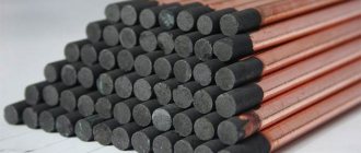
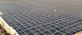
The essence of the electrode heating method is that electrodes of various types, configurations and materials are implanted into concrete or installed on the surfaces of a concreted structure. Reinforced frames are used less often as electrodes, since savings on consumable electrodes do not make up for energy costs, which are much higher with this method.
After connecting to an alternating voltage source (via a step-down transformer), a three-phase circuit is formed, in which one of the conductors is the concrete mixture. When current passes, an electric field is formed and thermal energy is released, which is required to heat the concrete structure. The number of electrodes is calculated in advance, and the concrete temperature and heating adjustments (including weather conditions) are made by selecting and adjusting the output parameters of the transformer. Constant monitoring of equipment operation, outside air temperature and the surface of the concrete structure is required.
During the hardening process of concrete, its electrical resistance changes in a complex nonlinear relationship. The initial resistance depends on the type of concrete, the water-cement ratio and the activity of the binder - cement. Cements from different factories give significant variations in the electrical resistivity of prepared concrete - from 8.5 to 16.5 Ohms. The dependence of current flow and heating on the concrete hardening phase is also taken into account when calculating circuits and loads.
Almost all load-bearing structures used in private construction are reinforced with steel rod reinforcement - a rod, and this option determines the maximum permitted voltage of 127V. The use of voltage more than 127V is permitted only with technical justification, in local areas and in the presence of special design developments.
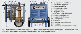
Heating the solution using a welding machine
Implementation of the method using welding equipment
Knowing at what temperature concrete is heated, you can use a welding machine for heating.
To implement this method, you will need the following equipment and materials:
- Several pieces of reinforcement;
- Incandescent lamps;
- Thermometer.
In this case, the fittings are located parallel to the circuit consisting of forward and return wires. Between them there are incandescent lamps, with the help of which voltage measurements will be made. To measure temperature, a very ordinary thermometer is used.
The hardening process of the solution is quite long and can take about a month. During the process of heating and hardening of the solution, the structure should under no circumstances be flooded with water or exposed to cold.
This method is applicable when it is necessary to heat small concrete poured structures and in acceptable weather conditions.
TMO for heating concrete purpose, characteristics,
TMO concrete heating is a development that allows for the casting and laying of ready-mixed concrete in a monolithic building at subzero temperatures without disrupting the technological process that provides the material with hardening and normal maturation conditions. We would like to tell you about the characteristics and purpose of equipment for transformer heating of concrete.
Methods
There are different methods for heating concrete for casting and winter placement.
The following technologies are used with varying frequency:
- Construction of shelters, heated houses, other structures and superstructures that prevent direct contact of the working area with cold air. Quite often used in conjunction with heaters powered by electric, solid fuel, diesel or gas. Refers to expensive and ineffective methods that are unsuitable for large-scale objects;
- Application of heated formwork. It assumes the presence of special equipment for the construction of formwork with heating elements, and a set of connecting and supply wires, transformers and system protection and control automation. Suitable for small structures, walls and other standard elements;
- Electrode heating of concrete. It is based on the thermal effect characteristic of the passage of electric current through a conductor with resistance, the only conductor here being the solution itself. It is characterized by low efficiency and enormous energy consumption, suitable for pouring vertical walls, columns and diaphragms;
- Warming up the concrete using the PNSV wire (1, 2). A special wire is placed in the formwork, which heats up when an electric current passes through it. Heating of concrete with TMO and wires is characterized by high efficiency and low energy costs, is suitable for various, as well as massive and non-standard structures, and is characterized by complex preparation;
- Infrared heating. Here the solution is heated with special radiating mats, but there is the problem of water evaporation. The method is suitable for slabs and small horizontal and thin-walled structures;
- Induction heating. Based on the phenomenon of electromagnetic induction: a coil with a conductor forms an alternating electromagnetic field, which induces a current in the reinforcement frame of the structure, as a result of which it heats up. It is distinguished by complex calculations and expensive equipment for the thermal effect and the number of turns.
Note! Analysis of all methods of increasing the temperature of the solution allows us to single out heating through wires as the most universal and effective, relevant for structures of different shapes and sizes and suitable for working with huge volumes of concrete. Then we will look at the main power source for electric concrete heating systems - stations and transformers that supply the conversion of mains voltage to acceptable values, and the regulation and supply of operating current at the site.
Then we will look at the main power source for electric concrete heating systems - stations and transformers that supply the conversion of mains voltage to acceptable values, and the regulation and supply of operating current at the site.
Why is this being done?
According to SNiP, technological heating of concrete is regulated if the minimum daily air temperature drops below 0°C. Its purpose is to prevent freezing of the raw concrete mixture, which leads to the formation of ice films in the thickness of the material and around the reinforcement.
Water is directly involved in the process of preparing concrete, but, turning into ice, it ceases to be part of the chemical hydration, preventing the mixture from hardening. In addition, when expanding, ice creates internal pressure and destroys bonds in freshly poured concrete. After the liquid thaws, the hydration process can resume, but some connections are lost forever, which leads to a decrease in the quality of the material and the durability of the structure.
Safety requirements for electrode heating
Warming up of structures reinforced with rod reinforcement is carried out at a reduced voltage - from 60 to 127V. To heat densely reinforced structures at higher voltages, a separate calculation and design is required. Connect voltage above 127V in some cases:
- The concrete element does not include a reinforced frame
- The heating area is local, the structure is free-standing and in no way connected with reinforcement frames, embedded parts and any current-carrying elements of neighboring structures
- Structures can be heated by the electrode method at a supply voltage of up to 380V only in cases where a short circuit to the reinforced frame is impossible (that is, the mass consists only of concrete). Warming up at high voltage can be allowed by calculation only for structures without reinforcement. Work on warming up or heating reinforced concrete and soil using 380V voltage is prohibited
For all electrical heating work, electrical safety rules must be followed.
Warm-up specifications
The following wiring requirements must be observed:
- the minimum temperature for using cables and special insulation measures in winter is +5°C;
- It is recommended to heat the mixture to +8°C (no more than +50°C);
- should be selected with such parameters that the solution does not lose moisture;
- Constant temperature control is important;
- at ambient temperatures below -30°C it becomes ineffective;
- After concreting, heating should be carried out within 5-7 days.
It is important to use high-quality wire when concreting:
- PNSV - heating cable with a galvanized steel core in a polyvinyl chloride insulating sheath;
- PTPZh - two-core, similar to the first type, but with a polyethylene coating.
PNSV is produced with a wide selection of core cross-sections from 1.0 to 6.0 mm2, which allows you to select and purchase the appropriate option for concreting in winter at the best price. In terms of flexibility, it belongs to the lowest class, third, but it is quite sufficient, since the maximum bending radius is 5 diameters of the wire thickness.
PVC braiding is very effective, since even at extreme current loads it does not melt, does not spark, and remains sealed. Thickness is from 0.4 to 1 mm, PNSV can withstand heating up to +80°C, which is sufficient for its main scope of application. Specific heat release power is from 20 to 40 W/m2, depending on the cross-section of the core.
The service life is at least 16 years, subject to compliance with technical requirements. The main advantages include resistance to high humidity, acidic and alkaline environments. First, the number and parameters of the PNSV cable are calculated in order to achieve the required thermal conditions. It takes into account the average daily temperature, warm-up time and laying pattern. The solution to this complex task should be trusted only to specialists.
Installation of PNSV brand wire is carried out in the following sequence:
- the optimal length of the segment is determined to be 17-28 m, at which the required thermal power will be provided, and the maximum current is 15 A;
- sections are laid evenly in the form of a loop or snake at intervals of 5 cm so that the ends extend to one side of the plane;
- the cable must not be allowed to touch other materials;
- connection is made to a single- or three-phase (star or delta) power supply network via PV1;
- It is necessary that the junction of the heating and connecting wires be on a concrete surface to ensure safety.
Before buying a PNSV cable, it is important to pay attention to the presence of galvanized conductors, since sometimes manufacturers, in order to reduce the cost, make ordinary steel ones, which oxidize in conditions of high humidity and lose their properties.
To ensure heating to a given temperature, 1.2-1.3 kW is usually required for a wire with a cross-section of 1.2 mm2. Therefore, step-down transformers are used to obtain a voltage of 70 W and a current in the range of 14-18 A. In some cases, a connection to a welding machine is used, provided that appropriate changes are made to the circuit and the power parameters are correctly configured.
The use of PTPZh wire is effective at ambient temperatures above -15°C. Peak heating – up to +60°С. The maximum voltage for which the conductors are designed is 1.5 kV, service life is up to 10 years.
This cable has a number of features regarding installation and connection:
- connecting wires for connecting PTPZh must have “cold” ends, that is, lower resistivity;
- the minimum step between heating lines is 15 mm;
- if the temperature regime is not observed, the insulation may be damaged and a short circuit may occur;
- to improve the quality of heating, the cables are wrapped in foil, thereby increasing its area;
- the laying scheme is similar, but you can connect two wires at one end, thus creating a loop, but the current power will have to be reduced, since there is a high probability of local overheating of the solution;
- When installing at temperatures below -10°C, care is important, as there is a high probability of damage to the insulating braid.
To reduce the cost of ties, cables with a cross-section of 0.6 mm are used, which are easy to install, their bending radius is minimal, and also have low power requirements.
Installation of electric heated floor
Experts and consumers recognize that an electric “warm floor” system is easier to install than a water one.
With a water structure, the concrete layer must be at least 5 cm. The cable heater is laid at 3-4 cm.
Working with the screed is a labor-intensive stage when installing a heating system. When laying the cable version, it can be replaced with a layer of tile adhesive.
By design, the cable floor can be in the form of mats, rolls or cables.
Heating mats are often used for small rooms (bathroom, toilet). The system looks like a cable mounted in a zigzag on a plastic mesh. By purchasing such products, you will avoid screeding work.
Electric underfloor heating is much easier to install
The cable tie has a higher power rating than mats. It is used as a replacement for the main heating system, for installing an “anti-icing” system (porch steps, walkways).
The installation process includes the following steps:
- preparation of the subfloor;
- laying an insulating layer;
- cable fastening system (metal or plastic slats, steel mesh);
- installation of temperature sensors;
- test connection of the system;
- pouring screed;
- installation of linoleum.
Linoleum is usually always laid on top of the screed
Thermal insulation is carried out so that the heat spreads to the floor and not to neighboring structures. The material must have a thickness of at least 3-4 mm. The effect is enhanced by a reflective foil layer. The material is attached to the floor without leaving gaps.
The cable is secured according to clear parameters. The bend, pitch of the cable, and the distance from the wire to the wall of gas and water pipes are taken into account. The wire is secured with special clamps.
Temperature sensors are an essential element of floor heating equipment. They come in two types. The internal elements are mounted directly into the floor structure, between the cable turns. External devices are located in the thermostat. Their readings track fluctuations in indoor air temperature. If the finishing floor covering is linoleum, it is better to use both types of temperature sensor.
Thermal sensors are essential elements of electric heated floors
Thermostats are used to maintain optimal temperature conditions. There are designs with manual control mode and programmable versions of the device.
During installation of linoleum, the floor heating system must be turned off.
Any products used to install heated floors are characterized by increased safety. It is provided with design features and a reliable control circuit.
When installing linoleum, the heated floor is turned off
Installation of electrodes in the structure
Local overheating of concrete has an extremely negative effect on its final strength, so all electrodes, regardless of their type, are installed most evenly. The minimum distances along the axes of the electrodes when using a transformer output voltage of 65V are 200 mm; at voltages from 85 to 120 V - at least 350-400 mm. To minimize the risk of local overheating, group arrangements of electrodes are used, and a group of electrodes is connected to one phase of the power supply at once. The distribution of electrodes in the group and the intervals are determined by the project.
The installation and fastening of electrode groups and individual electrodes is carried out taking into account safe distances to the reinforced frame. Displacement and contact of conductive parts and steel reinforcement are unacceptable. If two electrodes connected to different phases are short-circuited to the reinforcement, a short-circuit will occur, the results of which will be burnout of the current conductor wires, and possible melting and breakage of transformer parts.
The concreting process - laying and compacting the concrete mixture - is carried out with care to prevent the electrodes from moving from the design position and touching the reinforcement.
Minimum distances from the electrodes to the reinforcing bars of the frame during the warm-up mode under voltage:
- 55 V – 50 mm.
- 65 V – 70 mm.
- 85 V – 100 mm.
- 110 V – 150 mm.
If the minimum distances are not maintained, then local overheating of the concrete is inevitable. Therefore, in cases where it is impossible to ensure a minimum separation due to the dimensions of the structure or according to the scheme, then electrical insulation is performed on those sections of the electrodes that are at a dangerously small distance from the fittings. Insulation is done by placing an ebonite tube over the electrode. The metal of the strip electrodes is wrapped with roofing felt in two layers, with the insulation length being 100-120 mm.
All surfaces of heated concrete must be thermally insulated; heating without shelter is not allowed.
If massive and extended structures (surface modulus up to 6) are heated with electrodes peripherally, along the outer edges and kept in a thermos, then the minimum distance for any arrangement of strip electrodes at the corners of the structures is 200-220 mm; on straight sections - up to 300-350 mm.
The mode and placement of electrodes are prescribed according to calculations, and violations of the design and heating technology can lead to local or extensive burnouts of concrete or overheating of the concrete mixture above one hundred degrees, which can be fatal for concrete - not just lead to insufficient strength gain, but cause deep cracks in designs.
When performing the heating mode, strict control of the concrete temperature is necessary. In practice, the heating mode is regulated by turning groups of electrodes on and off or heating completely, while striving for smooth temperature changes. Concrete heating stations are equipped with instrumentation for automatic control of current, voltage and temperature of concrete. For the first three hours after entering the warm-up mode, the temperature is monitored once an hour, then once every two to three hours. The condition of the thermal insulation of structures is also periodically checked.
Timing
Warming up concrete begins with choosing the optimal scheme, taking into account the requirements of the construction site, region (Moscow requires some measures, Sochi or Norilsk - completely different), capabilities, etc.
The main factors that are taken into account in time and temperature calculations are:
- The average annual winter weather forecast for the region, taken over the previous couple of years, as well as the predicted average air temperature during a given winter period.
- Calculation of the module of the working heated surface, determination of the thermos holding time of the solution.
- Calculation of the average temperature of the structure during its cooling period.
- Accounting for information about the temperature of the finished concrete mixture, its isothermal properties (provided by the solution manufacturer).
- Determination of heat losses during mixture transportation and unloading.
- Determining the temperature of the mixture from the beginning of laying (the heat transfer to warm up the reinforcement and formwork is taken into account).
- Calculation of solution cooling time (in accordance with regulatory strength requirements).
All this data is used to predict the hardening time of concrete, to take into account heat losses during the pouring process, and heat radiation from the surface. But all this is quite approximate, so during the heating process you need to carefully monitor the temperature every half hour to an hour when heating and once every 12 hours when cooling. If the mode is violated, you need to increase or turn off the current by adjusting the parameters.
The technological map should contain a heating schedule indicating the optimal values and all important calculations performed in accordance with SNiPs and rules.
Warming up concrete is an extremely important event when performing repair and construction work in winter. Without the implementation of these methods, concrete simply will not gain standard strength, calling into question the strength, reliability and durability of the entire structure
Electric heating modes may be different
- Two-stage heating - heating of the laid mixture and isothermal holding. At the time of power outage, the concrete must gain a certain strength (set by the project as a percentage of the brand strength and depends on the responsibility, loads, operating conditions of the future structure, type of concrete, etc.). Heating in two stages with isotherm is prescribed for structures with a surface modulus greater than 15.
- Three-stage heating - heating, isothermal holding and cooling. The required strength will be provided by the time the heated structures cool down. The mode is used for elements with a degree of massiveness from 6 to 15.
- Two stages - heating and cooling with holding in a thermos, with complete thermal insulation of the structure and/or the use of heating formwork, depending on the values of sub-zero ambient air temperatures. Critical strength is achieved by the end of concrete cooling. The mode is assigned for elements with degrees of massiveness up to 6.
After compacting the concrete in the structure, the power to the electrodes is connected, and the minimum temperature of the concrete mixture is +5⁰С. Then the heating is increased, while the rate of temperature increase should be kept no more than 8 degrees per hour when heating elements with a degree of massiveness from 3 to 6, 10 degrees per hour - respectively for structures with a degree of massiveness from 6, and 15 degrees per hour - for rack-mounted - beam frame and thin walls (120 - 150 mm) with a length of up to 5.75-6.0 m.
For various types of cement, the maximum tolerances for concrete temperatures are calculated for any electrical heating modes. In private construction, Portland cement PC400 and PC500 (fast-hardening) is mainly used. For these cement grades, temperature limits are established for surface modules, respectively:
- From 16 to 20 - +55⁰С.
- From 10 to 15 - +65⁰С.
- From 6 to 9 - +70⁰С.
The isothermal holding time depends on the type of binder (cement activity), heating temperature parameters and the concrete strength assigned by the design. This time is determined by the type of concrete and is checked in the laboratory by testing cubic compressive strength. The cooling rate of the concrete structure must be minimal; the limit is for elements with a surface modulus:
- From 6 to 10 - 10 degrees/hour.
- From 10 and above - 5 degrees/hour.
The demoulding of concrete is carried out no earlier than its surface has cooled to +5⁰С, but the formwork should not be allowed to freeze with the concrete. After stripping, concrete is re-insulated in cases where the temperature difference between the atmospheric air and concrete surfaces is more than 20 degrees.
Winter concreting methods
Below we will consider all existing methods of winter concreting, their areas of application, and also give recommendations on the choice of concrete curing method depending on the type of monolithic reinforced concrete structures being erected in winter at low temperatures.
| Winter concreting methods | Features of the technology | Approximate energy consumption, (kW/h)/m3 | Application area |
| "Thermos" | At the time of laying, the temperature of the concrete mixture is at least 10°C; formwork – insulated; concrete cooling rate - no more than 50C/h. | — | Massive structures in which the surface modulus (the ratio of the surface area of the structure being built to its volume) Mp<3 |
| Through electrode heating | Temperature rise: at a speed of no more than 10°C/h; Isotherm temperature - no more than 50°C; Warm-up duration: until critical strength is reached | 80 – 110 | Lightly reinforced concrete structures: MP from 3 to 10, thickness – up to 50 cm |
| Peripheral electric heating | Temperature rise: at a speed of no more than 150C/h; Isotherm temperature - no more than 50°C; Warm-up duration: until critical strength is reached | 90 – 120 | Designs in which MP < 15; — with a thickness of up to 20 cm — one-sided heating and insulated formwork; - with a thickness of more than 20 cm - double-sided heating. |
| Preliminary forced electrical heating, including in formwork with repeated vibration | Warming up the concrete mixture in 10–15 minutes to 70–80°C. in bunkers/formworks (after compaction). At MP<5 it is enough to keep it “thermosically” in insulated formwork. If MP >5 additional heating may be required | 40 – 80 | Designs in which MP < 8. |
| Conductive heating or “heating formwork” | Temperature rise: at a rate of no more than 10°C/h; Isotherm temperature - no more than 50°C; Warm-up duration: until critical strength is reached | 100 – 130 | MP > 8. |
| Electric heating with heating wires | Temperature rise: at a speed of no more than 100C/h; Isotherm temperature - no more than 50°C; at contact with concrete, the heater temperature is no more than 80°C; Warm-up duration: until critical strength is reached | 80 – 110 | MP > 10. |
| Heating with infrared radiators | The temperature of the heated concrete surface is not higher than 80°C; protection against water evaporation from concrete is mandatory | 120 – 200 | Effective for walls and ceilings |
| Induction heating | Temperature rise: at a speed of no more than 150C/h; Isotherm temperature - no more than 50°C; concrete temperature at contact with reinforcement - no more than 80°C; Warm-up duration: until critical strength is reached | 100 – 150 | Densely reinforced reinforced concrete structures of linear type |
| Convective heating (heathouses, electric heaters) | Chamber traditional (general) greenhouse at temperatures up to 20°C. Local chamber greenhouse. | 120 – 200 | Structures with an MP index > 10 in confined spaces and outdoor temperatures above minus 30°C |
| Without heating using chemical additives | Restrictions on the type of additives: depends on the type of reinforcement and requirements for surface quality | — | Limitation on outside air temperature: up to minus 15°C |
| Steam heating (deaf or hot steam) | Temperature rise: at a rate of no more than 15°C/h; Isotherm temperature - no more than 50°C; Warm-up duration: until critical strength is reached | 90 – 140 | For any structures requiring heating |