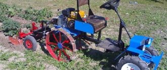
Walk-behind tractor and reverse gearbox for it
The clutch is located strictly between bevel gears, freely located on the main shaft.
This is how the reversing circuit in the gearbox is presented, which, if you look at it, is not too complicated. It only clings to the splines in the gears. This is what allows her to change the direction of the spiral-shaped gear. The cam, or fork, is represented by the clutch itself.
A reduction gearbox is a device that is designed to convert torque. There are worm, planetary and combined modifications. The engine with gearbox is capable of operating at high speeds. The standard model consists of a shaft, pushers and gear. If necessary, you can make a step-down device yourself.
Using gears
A walk-behind tractor with a gear reducer is more reliable and durable than one with a chain or belt drive. Gear structures are installed on factory products, and not only on walk-behind tractors. The units are small in size as a result of combining two gears with different diameters on one axis.
The required gear ratio can be provided by a planetary mechanism, in which satellite gears are installed between the outer and sun gears, mounted on a fixed ring - the carrier:
For a reduction gearbox, the sun gear is mounted on the drive shaft. The planetary gear carrier is mounted on a stationary housing, and the outer gear is connected to the actuator, rotating in the direction opposite to the sun gear.
The gear ratio of such a gearbox can be calculated as the ratio of the number of teeth on the sun gear to the number of teeth on the external gear.
To change the direction of the axis of rotation in gearboxes, a spatial planetary mechanism is used, in which the gears, in order to change the direction by 90 degrees, must be beveled to a cone of 45 degrees each. The diameter of the gears can be different, which can be used to change the gear ratio.
For a walk-behind tractor, such an angular gearbox is rarely made by hand, since planetary gears of the required size still need to be looked for. Changing the axis of rotation is often done using ready-made factory gearboxes or a worm pair.
Speed reduction gearbox
Topic Automatic gearboxes 5, 6-speed and DSG
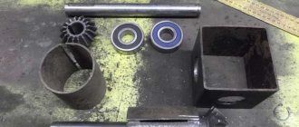
Its first element is the body, the location and interaction of all parts inside depends on it. Axes and shafts, gears, support bearings, sockets for them - this is its design. Cast iron or aluminum alloys are used for industrial designs. To assemble it yourself, you will either need an old frame, or you can weld it from steel. When welding, it is necessary to take into account that the metal is deformed and shrinks, so leave a little allowance for processing the main mounting sockets.
For the body, a 2-inch plumbing elbow is also used.
Gears are taken from old non-working chainsaws, pulleys from a washing machine.
There is another assembly option. No boring work is done, it is completely welded, and sections of pipes are taken as housings for the bearings. They are aligned as needed and then secured by welding and bolts.
The part at the top is made removable, and a hole is equipped at the bottom to drain the old oil.
The axle shafts are equipped with gears. Often, in a single-stage design, only the first ones are used, and the fit is carried out under tension, with pins, or a key. With this arrangement, the gears move with the shafts. The axis is used with an intermediate gear, which makes the direction of the shafts the same. It rotates freely along the axis with a minimum of clearance. They are protected from displacement to the sides by sides and washers. The shafts are made of 10-45 steel, with good machinability.
Bearings are supports. They take the entire load when moving inside the device. Functioning and efficiency depend on them. The closed type is suitable for a homemade device; they require minimal maintenance and are lubricated with lubricant. Their design depends on the forces encountered. If the device has spur gears, then single- or double-row simple ball gears are suitable. With a helical or worm mechanism, it is recommended to install roller, thrust-radial ones, since the load is greater.
What it is?
First you need to understand what a gearbox is. It is a mechanism that ensures the movement of the cultivator. The gearbox for a walk-behind tractor converts torque into driving force. The device is sometimes called a converter. The service life of walk-behind tractors depends on it, so it is very important to pay attention to the quality of parts when choosing .
The dimensions of the gearbox depend on the dimensions of the mechanized motor vehicle.
Gearbox assembly recommendations
Replacing the cuff of the secondary shaft of the VAZ-2107 gearbox
Diagram of the gearbox of a walk-behind tractor.
The method of fastening the sprocket can be very diverse. Depending on the design of the shaft, the sprocket can be fixed to it using a key, a flange, or sometimes even fastening using spot welding.
The driven shaft of the gearbox can be assembled from two axle shafts. At the ends of the axle shafts, counter flanges must be machined. The second stage driven sprocket is inserted into its seat between the flanges, and the axle shafts are assembled into a single unit using a bolted connection.
If possible, you can do it a little easier without using axle shafts and bolts. To do this, the entire shaft is turned on a lathe. Fixation on the shaft will be carried out using a key or, if necessary, welding. A significant disadvantage of this method, compared to the previous one, is the less reliable and accurate fastening of the sprocket.
Diagram of the design and operation of the reducer: a - gas does not flow through the reducer, b - gas passes through the reducer, 1 - fitting, 2, 3 - pressure gauge, 4, 8 - springs, 5 - valve, 7 - membrane, 9 - screw, 10 - chamber, 11 - valve.
In order to protect against dirt and foreign objects getting into the chain drive, the second stage unit of the gearbox is placed in a protective housing. In addition to the function of protecting the transmission, the housing is a reservoir for lubricating fluid, which ensures smooth operation and reduces wear of rubbing parts.
The body of the housing must be provided with coaxial mounting sockets into which bearings are installed to support the shafts. To install the driven shaft, ball bearings in a conventional cylindrical housing are used. The drive shaft is mounted on bearings with an eccentric housing.
Due to the peculiarities of its design, the eccentric can change its position in the seat by an angle of up to 15°. Together with the bearing, the drive shaft will also change its position, thereby, if necessary, adjusting the amount of chain tension.
During operation, the teeth of the driven sprocket of the second stage of the gearbox are immersed in oil poured into the housing. The rotation of the mechanism ensures uniform distribution of the lubricating fluid among the chain drive units.
The tightness of the casing can be ensured by installing standard sealing gaskets and seals on the bearing seats and along the split line of the housing. It is quite easy to select bearing sealing gaskets, because... All sizes in this case are standardized and interconnected.
In the case of sealing the case, the situation is somewhat more complicated. If you use a non-standard product or housing from any old models, it is quite difficult to find gaskets. The solution may be to use specialized oil-resistant sealants.
With correct calculation and careful assembly of all the parts of a homemade walk-behind tractor, the unit will be in no way inferior to its factory counterparts.
We recommend that you read
This circuit has a safety clutch. For the wheelbase value, see Chelyabinsk,
Gearbox with overdrive multiplier, providing 18 forward gears and 4 reverse gears. Net weight, excluding poured engine oil, is equal to kg.
The MTZ 92P tractor is designed for excavation work such as excavating soil, loading and unloading sand, crushed stone and other construction materials; cleaning of economic, construction and any work areas and areas; in the road construction industry; in the fleets of industrial enterprises. The transmission was divided into 17 gears: forward gear of 9 degrees with a speed range of 2.15...15.5 km per hour, reverse gear of 8 degrees with a speed range of 2...14.5 km per hour.
The MTZ 92P tractor is designed for excavation work such as excavating soil, loading and unloading sand, crushed stone and other construction materials; cleaning of economic, construction and any work areas and areas; in the road construction industry; in the fleets of industrial enterprises. The transmission was divided into 17 gears: forward gear of 9 degrees with a speed range of 2.15...15.5 km per hour, reverse gear of 8 degrees with a speed range of 2...14.5 km per hour. Magnitogorsk, city. The poor sound insulation is frustrating, there is not enough air conditioning - it’s quite hot to work in the summer, even opening windows can’t help.
You can purchase and install the following additional products from the factory dealer: Model D motor When installing tires The FDA consists of three parts and is detachable.
You can purchase and install the following additional products from the factory dealer: Model D motor When installing tires The FDA consists of three parts and is detachable. The transmission has a self-locking differential. To drive the Belarus 92p rear mounted implement, there is a PTO with a two-speed independent drive. New MTZ 92P in our farm
Related article: Yamobur MTZ
How to make a gearbox for a walk-behind tractor with your own hands
Diagnosis of gearbox faults
Two types of gearboxes, called worm gearboxes and chain gearboxes, have several small but quite important differences. They are contained in the characteristics that are inherent in the two types, but gearboxes operate with different factors: efficiency, angular speed, number of gears, as well as shafts, ratio between gears.
Gearboxes for walk-behind tractors, what are they?
When you have walk-behind tractors that are relatively cheap, they are often equipped with simplified assembly gearboxes that are not dismountable.
In this case, the service life is significantly reduced. Any additional possibilities are excluded, including: repair and, accordingly, assembly, replacement of parts, or disassembly to check the condition of the unit.
This means that the material from which the gearbox itself is made is of very low quality. Most of the parts presented in the assembly will not be sleeved. The gearbox diagram will allow you to present not only the principle of its operation, but also determine its service life.
Expensive walk-behind tractors have gearboxes with a more complex structure and the possibility of further assembly and disassembly. Maintenance can be carried out by correcting all problems in the operation of the gearbox. Repairs must be carried out in order to extend the service life of the operation.
It is important to replace faulty parts with other, more expensive elements. Lubricating the gearbox also extends its service life.
In most cases, the gearbox serves as a speed converter. That is, the angular velocity quickly and qualitatively goes to low. The input shaft will show a high angular velocity, but the output shaft will already be low.
Unforeseen breakdowns are prevented by constant and high-quality maintenance. With a stepwise variation in speed, the gearbox is called a conventional gearbox. In the case when it does not work according to a step system, it is called a variator.
Homemade bevel gear for walk-behind tractor
In principle, the gearbox does not have a very intricate structure; it is quite possible to assemble it yourself. First, make the correct calculation in rated power (Pn);Pn=Pe(hp)xFS. This will allow you to choose the correct angle to determine for the bevel gear. According to this principle, not only the number of possible revolutions in one minute will be calculated, but also the torque will be calculated.
A self-made gearbox needs to determine its operating conditions. Among them there is radial load, or axial load, which is present on the shafts at their ends. Its operation will be optimal if the temperature and type of lubricant are selected correctly.
After completing all the above steps, you can proceed to assembly. You can choose a factory case. The diameter of the housing will tell you what kind of housing the bearings for the shaft will have. A caliper and a good quality drill will help. Next, we take two bearings under the shaft itself.
It is important to install a steel flange on the front of the gearbox. Accordingly, inside: a bearing, necessarily flanged, and a washer. The flange is attached to the generator itself using screws
The steel key, together with the drive gear and driven gear shaft, must be selected in advance. All nodes connecting to the mechanism, which is a transmission, are connected to the rotary generator. It has a pulley that provides V-belt transmission. It should be secured to the driven shaft using a nut with a spring washer.
Controls
Some controls (carburetor air damper, power take-off shaft, etc.) are located on the corresponding components and assemblies.
Typically, the clutch control lever and the engine emergency stop lever are located on the left steering rod, and the gas handle, wheel drive lever and brake lever (if equipped) are located on the right steering rod. The design of the steering column of walk-behind tractors, as a rule, provides for adjustment of the position of the handles in the horizontal and vertical planes. The figure shows the controls of the SunGarden MF360 walk-behind tractor.
Additional information about the operating hours of the online store on holidays and weekends. Main news and events that are relevant to the work of the store. Brief, necessary information about simple issues related to the work procedure.
Choosing the right cultivator is a simple process, even if you are going to buy a cultivator for the first time and have never used it before. The first thing you need to pay attention to when choosing a cultivator is the power of its engine.
The power of the cultivator engine should be related to the area of your cultivated area. The larger the plot of land you have, the greater the engine power of your cultivator should be. So, to cultivate a plot of land of 10 acres, a cultivator with an engine power of 4-5 hp is sufficient.
Cultivators such as Sungarden T 250 OHV6.0, CAIMAN COMPACT 50C S. Craftsman 29802 and other cultivator models will cope with this task. Of course, a plot of 10 acres can be cultivated with a cultivator with a lower power engine of 3 hp.
In this case, you will have to make stops so as not to overload the cultivator engine. It should also be noted that the greater the engine power of the cultivator, the greater the width of plowing with the cultivator in one pass, the faster it will be possible to cultivate the entire plot of land.
In addition, more powerful cultivators also have a greater depth of plowing of the soil. Cultivators with an engine power of 3 hp. suitable for processing plots of 3-6 acres. For plots with an area of 12-15 acres, it is better to select a cultivator with an engine power of 6-7 hp.
The second thing you need to pay attention to when choosing a cultivator is the number of speeds at which the machine can operate. The cultivator can have one forward speed. Such cultivators are designed for cultivating ordinary soils in garden plots that are regularly cultivated.
These include middle-class cultivators: Sungarden T 250 OHV6.0, Sungarden T340 OHV7.0. Sungarden 345 OHV7.0, CAIMAN COMPACT 50C S. Craftsman 29802, etc. Thus, these cultivators are suitable for regular cultivation of an ordinary garden plot.
The cultivator can have two forward speeds. In this case, the cultivator has an additional gear with reduced speed, designed for cultivating heavy soils or soils that are not regularly cultivated (for virgin soil). These include heavy class cultivators:
Sungarden T390 OHV7.0, Sungarden T360 OHV7.0.. Saturn HSD1G-80, etc. The third thing you need to pay attention to when choosing a cultivator is the presence of reverse or reverse gear. Middle-class cultivators may or may not have reverse.
Such cultivators, as a rule, weigh 40-50 kg, so control can be done without reverse. But the presence of reverse or reverse makes the work more comfortable and easier. This is especially noticeable when working near various obstacles (fences, for example) or in some narrow, limited areas when it is constantly necessary to make efforts to rearrange the cultivator.
Buying a cultivator with or without reverse in this case is a personal choice. Heavy class cultivators weigh more than 60 kg and have a reverse as standard. When choosing a cultivator, you also need to pay attention to some technical features of its design.
The cultivator may have a worm or chain type gearbox. The worm gearbox is easier to maintain. Such gearboxes are used only on middle-class cultivators. Worm gear cultivators are Champion BC 5602 Sungarden T 250 OHV6.
0, Viking HB 585, Viking HB 445, etc. Cultivators with a worm gearbox have a motor with a vertical shaft. Such cultivators can have a modular layout; the engine can be easily detached from the cutters. This is convenient when transporting the cultivator.
The chain gearbox is more resistant to overloads, has a slightly more complex design and is a little more difficult to operate. The chain-type gearbox can be used on both medium and heavy class cultivators. Thus, the medium-class cultivator CAIMAN COMPACT 50C S and the heavy-duty cultivator Sungarden T390 OHV7.0 have chain-type gearboxes.
DIY gearbox
Despite the abundance of technical devices, many craftsmen undertake to make a gearbox for a walk-behind tractor with their own hands. This process does not require the use of smart factory machines. It is enough to have a standard set of tools: an angle grinder, welding fixtures, a drill and drills of different sizes, a screwdriver, and hammers. Among the parts for the converter itself, you should have shafts and bearings, sprockets with appropriately sized chains, gears and belts.
Preparation
The most important element in assembling a walk-behind tractor gearbox is preparation. Without preliminary calculations, determination of dimensions and the correct number of crankshaft revolutions, it will not be possible to successfully assemble the gearbox onto a walk-behind tractor.
Calculations are carried out in the following order:
- determining the engine crankshaft speed. This number cannot always be the same, since if you press the gas pedal, this number will undoubtedly increase. Therefore, to avoid errors and inaccuracies in further calculations, it is necessary to take the number of revolutions + 10%;
- the next stage is determining the number of revolutions of the suspension axis. We take the wheel size as a basis and use the formula to determine the amount of run-out per full revolution. Next, we design this for the normal speed of the walk-behind tractor - 3-5 km/h.
Assembly
If you have a strong desire, have the appropriate tools, and also have basic assembly and disassembly skills, you can assemble a gearbox for a walk-behind tractor of any modification. However, the lightest would be a chain gearbox. It is easy to assemble, reliable, and the materials for its manufacture are always available.
So, assembling a homemade gearbox for a walk-behind tractor occurs in the following way:
- The housing for the product can be an old gearbox, or you can weld the metal plates together with your own hands. The housing is the most important component because it protects the gearbox from mechanical damage, dirt, dust and other objects;
- a sprocket must be secured to the output shaft of the motor;
- then we attach the driven shaft to the sprocket, as before we attached it to the output shaft;
- if the shaft is formed from 2 axle shafts and the driven sprocket is fixed in the middle, the design will be more reliable. Next, secure everything with bolts;
- make holes in the protective housing for fastening and connect it to the main structure. It also holds liquid lubricant inside the mechanism;
- Use sealing gaskets around the edges of the housing.
This is interesting: the design of the carburetor of the Cascade walk-behind tractor.
If all of the above steps are performed correctly, then the gearbox for a walk-behind tractor, made by yourself, will work no worse, or even better, than the factory analogue.
Change of oil
An important element of unit care is maintaining a normal amount of oil in the gearbox. If you lose sight of this point, the remaining old oil can seriously damage the parts. If you notice oil leaks on the outside of the housing, rest assured that this is insufficient sealing or a problem with the gaskets.
It is better to use high-quality transmission oil for a walk-behind tractor.
Such data is usually described by manufacturers in the instructions for the mechanism.
General rules for changing oil:
- 25-50 hours from the start of operation of the mechanism - the first oil change;
- 100-250 hours from the start of operation or after 1-2 years of storage is the normal frequency of checking the oil.
Self-assembly of the stroke reducer
Having all the necessary spare parts, you can begin assembling the speed reducer with your own hands. In order for the finished structure to cope well with its functions, you should act strictly according to the algorithm described below:
- First, make all the necessary calculations so that the result of the work is a well-balanced design. As a generator, you can take an element from the domestic Ural motorcycle;
- The main thing that is required from the device is high power and stable torque;
- Next, start cutting out the shell of the two bearings that will be needed for the drive shaft. It will start the gear. When working, take into account the diameter of the gearbox;
- Then you need to decide on the bearings. The flange must be located on the opposite side of the gearbox. There should be a metal washer inside it;
- Next, install the driven shaft on which the gear will sit. The product must be connected to the rotary generator shaft and transmission mechanism;
- Finally, you will need to secure the pulley to the driven shaft using a spring nut and washer.
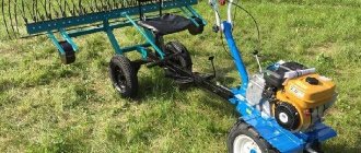
Having made the creeper, it will need to be tested. To check the device, it should be connected to the hitch of the unit, and the wheels for the cultivator should be installed. If you did everything correctly, the wheels will spin slowly, while the cultivator itself will be pressed to the ground.
When choosing wheels for a motor cultivator that will work in tandem with a speed reducer, you need to pay great attention to their diameter. There is no need to choose too large parts so as not to load the unit’s motor
Wheels with a diameter of 25 to 30 cm will be optimal.
https://www.youtube.com/watch?v=n_GAGsHClog
If homemade devices are planned to be used in conjunction with other attachments, for example, for a plow, then the creepers must have sufficient power to press the equipment to the soil. Be sure to take this into account when preparing spare parts for the manufacture of the device.
A creeper for a motor-cultivator is used at high speeds of the motor-cultivator, when it is necessary to reduce it to a speed effective for cultivating the land. Creepers are best used when working with additional trailed equipment, trailers, hilling soil and removing snow.
Purpose and types of gearboxes
Diagram of the angular gearbox of the walk-behind tractor: 1 - retaining ring, 2 - adjusting ring, 3 - bevel gear, 4 - adjusting rings, 5 - bearing, 6 - intermediate gear shaft, 7 - upper housing, 8 - output shaft, 9 - adjusting rings , 10 — bearing, 11 — bevel gear, 12 — retaining ring, 13 — boot cup, 14 — boot, 15 — cuff, 16 — adjusting rings, 17 — lower housing, 18 — adjusting shim, 19 — bearing, 21 — cover , 22 - gear, 23 - gear, 24 - shaft.
An important element of the walk-behind tractor design is the gearbox. It transmits torque from the engine shaft to the working tool or wheels of the unit, depending on the design. Thanks to the features of the device, torque is not simply transmitted, but is amplified with a simultaneous reduction in the number of revolutions of the driven shaft.
According to their design, gearboxes can be of several types:
- Geared. The gearbox consists of shafts with cylindrical and bevel gears mounted on them. By design, gear reducers can be implemented in a straight pattern (torque is transmitted through a spur gear) or angular (a bevel gear is used to transmit torque from the driven shaft directly to the gearbox).
- Gear-worm. Used with a vertical engine crankshaft. The gearbox consists of a worm gear and a worm (a metal screw with a large-pitch rectangular thread). A special feature of this gearbox is the transmission of rotation at an angle of 90°.
- Chain. Torque from the engine to the gearbox shafts is transmitted by a metal chain that rotates the sprockets.
- Belt. It is analogous to the chain method with the only difference that instead of a chain, a V-belt or rectangular belt is used, and instead of sprockets, pulleys with profile grooves are used to hold the belt.
The design of a motor cultivator often uses angular gear-worm or chain gearboxes. Gear reducers are used in the designs of powerful units. The belt transmission method is quite rare, because It is believed that the belts are prone to breaking and slipping from their seats.
Motor cultivator, power, reverse, engine hours.
Questions are ripe when choosing:
- How necessary is reverse and in what cases?
- What power should I use to attach the plow?
- Is 1500 hours a lot or a little?
- Which gearbox is better/more durable? Chain or worm?
- Has anyone used MasterYard?
Well, in general, what are the features and what to look for when choosing?
AliBaba wrote: what to look for when choosing
What volume of work are you planning? Maybe it makes sense to think between a walk-behind tractor/motor-cultivator?
6 acres and with a break of a couple of days the same amount, and then, accordingly, then all sorts of hilling and so on.
The indicated engine life is confusing. at MasterYard. B&S 1200 and Subary 2500, although if you do the math, 12000 should be enough for 10 years with such volumes
- How necessary is reverse and in what cases?
It’s better with reverse, but you can do it without it if you have the skills that you will acquire after cursing yourself a thousand times for not taking it with reverse.
- What power should I use to attach the plow?
Better at least 6 l/s. But we must take into account that this is a plow for a walk-behind tractor; a cultivator is not suitable for this (it’s too light).
- Is 1500 hours a lot or a little?
Enough for your life.
- Which gearbox is better/more durable? Chain or worm?
- Has anyone used MasterYard?
plowman Thanks for the answer to the point
AliBaba wrote: “answer to the point”
Why is it in quotes? Or were you expecting a “dissertation” (substantiation, links, technical documentation) in response?
This was written as a definition/quote and not as irony. So to speak, a standard expression.
Well, clearly, I hoped to think so too. With coming.
plowman wrote: Better at least 6 l/s. But we must take into account that this is a plow for a walk-behind tractor; a cultivator is not suitable for this (it’s too light).
In my opinion, forces are not as important as mass.
valerich wrote: Not only forces are important, but mass.
Dear Valerich! Happy New Year to you personally! Mass, weight, lightness-heaviness, it’s clear what is meant.
Does anyone have any opinions about the MASTERYARD engine? what is this?
However, the engine there is a LONCIN LC170F 212CC Gasoline engine, although its resource and suitability could not be found on the Internet.
plowman wrote: Quote: Posted by AliBaba
- Which gearbox is better/more durable? Chain or worm? I think chain.
But do not accidentally confuse it with a belt one; many imported cultivators, even with 5-6 l/s engines, have belt gearboxes (maybe they are of super quality, but for me this is surprising).
And here we found a little about LONCIN.
It remains to find out what kind of engine the Robin Subaru EP 16 is then.
Nobody really said anything.
Subaru EP is a normal engine, an amateur one, like a Honda GC. If you don’t carry the cart 15 km there and back every day, it will last for a very long time.
plowman wrote: But don’t accidentally confuse it with a belt one; many imported cultivators, even with 5-6 l/s engines, have belt gearboxes (maybe they are of super quality, but for me it’s surprising).
There are no such gearboxes. There is a belt drive.
plowman wrote: many imported cultivators, even with 5-6 l/s engines, have belt gearboxes
Please show me at least one of many.
andrexS wrote: There are no such gearboxes.
AlNik54 wrote: please show me.
I won't show you, I'll name you. Efco MZ, Craftsman, Eurosysems, Viking and many others. A very narrow gearbox, made of sheet steel (tin), non-separable, the halves are rolled and the seam is sometimes covered with plastic; a belt drive is used in the gearbox.
the plowman wrote: I won’t show you, I’ll name you. Efco MZ, Craftsman, Eurosysems, Viking and many others. A very narrow gearbox, made of sheet steel (tin), non-separable, the halves are rolled and the seam is sometimes covered with plastic; a belt drive is used in the gearbox.
You must be joking? These cultivators use a chain.
Talk nonsense carefully, trying not to spill it. Nonsense is good when it is complete!
the plowman wrote: I won’t show you, I’ll name you. Efco MZ, Craftsman, Eurosysems, Viking and many others. A very narrow gearbox, made of sheet steel (tin), a belt drive is used in the gearbox.
you confuse the concepts of gearbox and transmission
A gearbox is a mechanism consisting of gear or worm gears, made in the form of a separate unit, and used to transmit rotation from the engine shaft to the shaft of the working machine. The kinematic drive diagram may include, in addition to the gearbox, open gear drives, chain or belt drives. (With)
For example, the Efco MZ 2085R has a primary transmission that is a belt and a secondary transmission that is a chain.
Basic elements of a mechanical system
To support the main elements, the gearbox (speed reducer) is provided with a system of shafts and axles. Single-stage designs use shafts with rigidly seated driven and driving gears. Rigidity of fit is achieved through the use of keys or splines. Lateral displacements are adjusted with special nuts that press gears or sprockets against thrust collars. The material used is structural steel. It is perfect for making a creeper for a walk-behind tractor or cultivator.
Bearing units are supports for steel axles and creeper shafts on a walk-behind tractor. Bearings bear the main load during operation of the power unit.
Whether the speed reducer for a motor cultivator will work normally depends on the correctness and quality of the bearings. For homemade designs, bearings with closed cages (closed type) are better suited. This will save you from having to regularly change the lubricant. The type of gearbox bearings depends on the type of loads taken. Support bearings are installed on a creeper for a walk-behind tractor with straight gears, and thrust bearings are installed on gears with an oblique tooth profile and worm shafts. They are usually subject to longitudinal axial forces from an electric motor or internal combustion engine.
The gears and sprockets in the gearbox determine the speed and nominal rotation speed of the output shaft. For their production, special equipment and equipment are used. It is better not to make the creeper gears for a walk-behind tractor with your own hands. Buy ready-made gearing in specialized stores.
Whether the speed reducer for a walk-behind tractor will normally accept dynamic loads from the power unit depends on the correct selection of geometric dimensions and gear ratio. When installing gears, all necessary clearances must be maintained. To do this, carefully study the drawings. Clearances directly affect the ability to absorb significant loads from an internal combustion engine or electric motor.
The step-up and step-down gearbox for a minitractor is lubricated with I-20 industrial oil. The oil level is determined taking into account the operating conditions of the unit. Oil seals are used to prevent leaks.
Manufacturing of a reversible gearbox
If you want to build a unit at your own discretion, then you cannot do without a borrowed housing. It is impossible to do it yourself outside of factory conditions. The material used is cast iron or aluminum alloy. The body is produced using special equipment.
To make a reversible gearbox at home, you need to start with the housing. If it was not possible to select from other mechanisms, then it can be built from a gas pipe with thick walls with an outer diameter of 2.73 cm. Internal components: axles, gears.
A homemade reverse unit can actually be assembled from the elements that make up the main gear on a used GAZ-69 car. Hubs, bushings for reverse, sprockets, rod, fork are machined from metal. 45 steel is suitable for this. Finished parts must be hardened. You should be very careful in the manufacture of cams on the hubs, as well as reversible bushings, since they will be subject to increased dynamic loads. The drive and driven gears must be isolated from each other by a gasket, the thickness of which can be adjusted to the degree of their pressing.
Stages of work to create this device
- Installation of drive sprockets on the input shaft. In this case, installation can be done by spot welding, flange or key connection;
- Assembly of driven shaft axles;
- Installation of the driven sprocket;
- The case can be picked up from disassembly and adjusted or made by yourself. At the same time, it is necessary to make technological holes in it for oil seals and bearing connections;
- Installation of closed type ball bearings. An excellent option would be cylindrical ones. Their installation is carried out by tension;
- The drive shaft is mounted on eccentric bearing supports with the ability to adjust the chain tension by at least 15 degrees;
- At the final stage, a lid with a sealing gasket is installed.
Having decided to do this, it is better to first assess your strengths, knowledge and skills in handling the tool, so as not to get into trouble by spending a decent amount of money, a lot of time and effort, and at the same time, without creating the necessary device, but if you are an existing or former mechanic, you can safely get down to business.
The most important part of the walk-behind tractor is the drive. It is the main one of all the elements presented in the walk-behind tractor. Therefore, when there is a need to purchase a gearbox, all its further operation, and even the functionality of the walk-behind tractor, depends on the quality.
A gearbox for a walk-behind tractor is a certain type of device capable of transmitting and appropriately converting torque, for which mechanical transmissions are conductors. Accordingly, agricultural machinery will work more productively.
Transmission
By type, transmission units (gearboxes and gearboxes) can be gear, belt, chain, or various combinations of both.
Classic gear transmission
, consisting only of cylindrical and bevel gears, is used mainly on heavy walk-behind tractors and some models of medium-sized machines. As a rule, it has a reverse and several lowering steps.
The figure below shows the gear transmission of the Ugra NMB-1 walk-behind tractor, consisting of cylindrical and bevel gears. The engine is rigidly attached to the gearbox, which in turn is rigidly connected to the bevel gear. The design of the NMB-1 walk-behind tractor does not have chain and belt drives, which, according to its developers, are an unreliable link in transmissions due to the tendency to breakage, damage and belt slippage.
The torque from the crankshaft is transmitted to the drive shaft 16 (Gearbox Diagram) of the gearbox and is removed from the bevel gear of the driven shaft 15 by the vertical shaft 6 of the angular gearbox (Angle Gearbox Diagram), which transmits rotation to the hexagonal shaft of the 8 drive wheels.
The design of the gearbox is a mechanical two-way with 3 forward gears and 1 reverse. The transmission has two power take-off shafts (A) and (B).
Gear-worm transmissions
, consisting of two gearboxes - an upper gear and a lower worm gear - are usually used on light walk-behind tractors. The engine crankshaft is vertical. Sometimes cars with a gear-worm transmission are equipped with a centrifugal automatic clutch. This design of the walk-behind tractor ensures increased compactness of the unit.
Belt-gear, belt-chain and belt-gear-chain transmissions
are quite common in light and medium-sized walk-behind tractors. The engine rotates the shaft of a gear or chain reducer using a belt drive, which is also a clutch. Gear-chain drives are often implemented in a single crankcase.
In a belt drive, to change the speed of movement of the walk-behind tractor and power take-off, the pulleys may have an additional groove. The advantages of such a transmission include simpler disassembly and assembly of the walk-behind tractor than in the case of a gear transmission.
The figure below shows the V-belt transmission of the GreenField walk-behind tractor model MB-6.5 (with a belt-gear transmission), which, along with transmitting torque and reducing the speed, also performs the functions of a clutch and gearbox (speed shifting).
The clutch function is realized using a tension roller and a control mechanism consisting of a rod and a system of levers that allow you to change the position of the roller, which tensions or loosens the belt and, accordingly, turns on or off the transmission of torque from the engine to the gearbox.
A similar scheme is implemented in the domestic walk-behind tractor Salyut 5, shown in the figure below. The V-belt drive transmits rotation to the gear reducer of the walk-behind tractor.
As a rule, walk-behind tractor transmissions have power take-off shafts
, ensuring the transmission of torque to the working parts of the machine. According to their type and location in the transmission, power take-off shafts can be independent, located before the clutch and rotating regardless of its state (disengaged or engaged), or dependent, located after the clutch, and synchronous with a specific gear. One walk-behind tractor can have several power take-off shafts - different in type and rotation speed.
Main types, their purpose
In the household, walk-behind tractors and cultivators are most often used. According to their design features, they can be installed:
- Gear mechanism. Bevel or cylindrical gears are pressed onto the drive shafts. This design allows them to be used in direct transmission of rotation from the engine. Can be used as an angular gearbox for a walk-behind tractor, while the design uses a bevel gear.
- The device is gear-worm. Most often installed with a vertical engine crankshaft. A gear with a certain number of teeth and a worm screw with a certain thread pitch is a schematic description of the type of device. The main feature is the transmission of rotation of the engine shaft at a right angle.
- Chain device. The shafts are equipped with toothed sprockets. They are wearing a special chain, with the help of which torque is transmitted from the motor. For good performance, the chain is tensioned using a tensioner roller.
- Belt device. Rotation is transmitted using belts. Pulleys with grooves for belts are pressed onto the shafts, and the belt is tensioned using a tension screw.
Most often, in equipping the angular gearbox of a boat motor, walk-behind tractors and other mechanisms, a chain, gear or gear-worm gear is used. Previously, the main one was the belt system; due to breaks, the belt slipping off the pulleys, its operation was considered unreliable.
https://youtube.com/watch?v=zjBReRfGM3g
https://youtube.com/watch?v=zjBReRfGM3g
Types of mechanisms
According to the method of operation and action, all transforming mechanisms for walk-behind tractors are divided into several types:
- angular;
- downward;
- reverse with reverse speed (reverse gearbox);
To redirect rotational energy from a vertical drive to a horizontal plane, an angular gearbox using bevel gears (bevel gearbox) is used.
Reducing the number of revolutions and increasing the power of the drive mechanism is provided by reduction gearboxes, or creepers for the walk-behind tractor. They are considered the most reliable for operating a diesel or gasoline air-cooled walk-behind tractor. This allows them to be used for particularly difficult work - for example, plowing heavy soil or harvesting potatoes using a potato digger.
In a special article you can find drawings of a potato digger for a walk-behind tractor.
Preparatory work
Motoblock device.
When making a homemade walk-behind tractor, before starting to manufacture the gearbox, it is necessary to make at least an approximate calculation of it.
Based on the calculation data, we can estimate:
- gear ratio;
- gearbox type;
- torque values;
- the magnitude of the loads on the shafts;
- overall dimensions of transmission mechanisms (depending on the type of gearbox selected).
You can make a homemade walk-behind tractor with a gearbox that works on different principles. However, gearboxes with chain drives are most often used in home-made units. This is due to a compromise between the availability of component materials, the reliability of their operation and the relative ease of assembly.
For production you will need:
- sprockets with a pre-calculated number of teeth, providing the required gear ratio;
- driven shaft;
- bearings of the required size for installing the drive and driven shafts;
- chains of the required length;
- metal corners for attaching the protective housing;
- protective housing (crankcase).
Equipment
Converters are either collapsible or non-dismountable. Basically, the latter type can often be found in the configuration of budget walk-behind tractors. They feature inexpensive spare parts that cannot be replaced. In the event of a breakdown, there is only one way out - replace the entire gearbox. The service life of such models declared by the manufacturers is 1-2 seasons, provided they are used correctly.
More expensive equipment can boast of a dismountable gearbox that can be repaired: failed parts can be replaced with new ones. Therefore, the service life is several times longer compared to inexpensive devices.
The converter package consists of:
- Cases - collapsible or not.
- The rotor shaft is responsible for torque.
- Gears of different sizes.
- Chain or belt - depends on the type of gearbox. In the case of a chain transmission, movement occurs due to sprockets - star-type disks. If the transmission is belt driven, then the equipment has pulleys on which the belt is put.
- Bearings - reduce friction between rotating elements and ensure their free rotation.
Through these components, movements are transmitted from the motor to the attached parts. Belt converters are weaker and unreliable. If the torque is high, then the belts begin to fly off the pulleys. But such a structure has a positive effect on the engine shaft. This situation can be avoided by replacing them with gear ones. But then you will have to change the pulleys too.
All parts are located inside the case. In addition to the installed set of components, you can also add elements for lubrication of bearings inside the device. These include an oil pump or a cooling device.
How to make a reduction gearbox
One of the main and critical parts of a reduction gearbox is its housing. The relative position of the axes and shafts, the gaps between the gears and the alignment of the sockets for the support bearings depend on how correctly it is designed and manufactured. In industrial gearboxes, almost all housings are made by casting from cast iron or aluminum alloys, but at home it is practically possible to do this unreal. Therefore, it would be best to either select and modify a ready-made housing to suit your needs, or make it welded from sheet steel. However, in this case, you need to remember that during welding the metal can “lead”, and in order to maintain the alignment of the shafts, it is necessary to leave an allowance for the final processing of the bearing seats. Some craftsmen act differently - in order not to suffer from boring work, they weld the body completely, and use sections of pipe as seats for bearings, which are set in the desired position and only then finally secured in place with bolts or welding. In order to facilitate the maintenance of the gearbox, it is recommended to make the top cover of the housing removable, and provide a drain hole at the bottom to drain the used oil;
The shafts and axles of the gearbox serve as supports for the gears. As a rule, in a single-stage gearbox only shafts with rigidly mounted gears are used (pressure fit, keyed or splined). That is, both gears rotate together with their shafts. The axis is used when we need to insert an intermediate gear into the gearbox (for example, to ensure the same direction of rotation of the input and output shafts). Such a gear rotates freely with minimal clearance on its axis, and from displacement to the side it is fixed either by a thrust collar and a nut, or by locking split washers. It is recommended to use steel 10...45 as a material for shafts, which has sufficient strength and is easy to machine;
The bearings in the gearbox serve as supports for the shafts and absorb the loads that arise during operation of the gearbox. The performance and reliability of the gearbox as a whole depends on how correctly the bearings are selected. For a homemade gearbox, it is better to choose closed-type bearings, which are lubricated with grease and require a minimum of maintenance. The type of bearings depends on the type of load taken. If spur gears are used, conventional single or double row ball bearings will be sufficient. If the gearbox has helical gears or a worm gear, then an axial load is transmitted to the shaft (and, accordingly, the bearings). In this case, you will have to provide a roller or ball angular contact bearing;
No less important parts of the gearbox are the gears. It is with the help of gearing that we change the speed of rotation of the output shaft. To manufacture gears, special metal-cutting equipment is required, so it will be economically feasible to use ready-made parts from decommissioned units. It is the geometric dimensions of the gears and their gear ratio that will determine the interaxal distance between the gearbox shafts, as well as the layout of its housing
When installing gears, it is important to correctly set the gap between them, since the load capacity and noise level during operation of the gearbox depend on this. Liquid industrial oil of grade I-20 is well suited for lubricating gears, which is poured to such a level as to cover the teeth of the lower gear.
The remaining parts will be lubricated by spraying oil throughout the internal cavity of the gearbox;
Shaft seals are needed to prevent oil from leaking out of the gearbox. They are installed at the shaft outputs and are usually secured in bearing caps;
Safety coupling. In order to avoid emergency destruction of gearbox parts from excessive load, a so-called safety clutch is usually used. It can be in the form of a shear pin, spring-loaded friction discs or a bellows and is selected locally;
Bearing caps. These parts greatly facilitate the installation and maintenance of bearing units and can be blind or through. You can select them from ready-made parts or turn them on a lathe.
Diagram of a gearbox assembled from parts of a decommissioned car
This gearbox is assembled from parts of the main drive of the GAZ-69 vehicle. The bevel gears rotate from the drive sprocket, which is mounted on the shank. The torque is then redirected to one of the two driven gears, which rotate in bearings numbered 206 on the spline shaft. At the right time, the gear that engages with the reverse sleeve on the central spline of the shaft works. Then the cardan transmits the movement to the differential or the drive wheel of a mechanical vehicle.
Read also: Homemade devices for circular saws
And the final important point for owners of walk-behind tractors or mini tractors. When purchasing a mechanism, price also plays an important role, because cheap units are mostly equipped with non-separable gearboxes. Such mechanisms are unreliable for long-term operation. If necessary, this gearbox cannot be repaired, disassembled or reassembled, or parts replaced. It is made of low quality metal, its parts are not gelled.
Expensive units are equipped with gearboxes that can be disassembled, which allows for gearbox maintenance and repairs. Like any other mechanical vehicle, it needs constant rechecking, repair, and updating, and the gearbox must be constantly inspected and monitored. From time to time it is necessary to carry out diagnostics of the mechanism to prevent breakdowns in the future.
When purchasing, it is more profitable to buy a more expensive gearbox, because it will serve you longer.
The pride of many summer residents is a homemade walk-behind tractor, assembled with their own hands from parts that have served their age. Installing an electric motor or a small gasoline motor from an old scooter or motorcycle onto a frame with wheels is not difficult even for a novice amateur mechanic. But what you have to think about is the gearbox for the walk-behind tractor.
Assembling a homemade cultivator
Its power is 1.4 liters. With. It is also suitable for use as a cultivator unit.
One of the most important stages of work is connecting the base with cutters to the trimmer.
This operation is greatly simplified if the end of the shaft has a reverse thread, to which the equipment is simply screwed. The DDE GB 32 RD trimmer is just such a model.
In such a case, a nut of the required diameter is welded onto the steel tube. There are also trimmers that have threads inside the shaft.
How to make a cultivator from a drill with your own hands
If you need to perform work in the garden with a cultivator, but this must be done with great precision, you can make the tool in question from a conventional drill. To do this you will need very little:
- working drill;
- a steel rod that can compress the chuck of an existing drill;
- cutters.
You also need to have a tool for processing metal surfaces:
- Bulgarian;
- emery;
- welding.
Preliminary drawing up of drawings for a cultivator made by yourself is not required.
A steel rod, the optimal diameter of which is 10 mm, will act as a shaft that transmits rotation from the drill motor through the chuck to the cutters.
Any sheet metal can be used as a milling cutter if its thickness and hardness allow working with problematic soils.
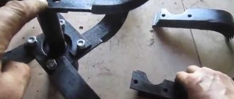
You can also use ordinary metal corners, which are 10 mm wide and 100-150 mm long. Using a grinder, ordinary flat rectangles are made from them.
Then they bend at an angle of 90 degrees. The cutters are sharpened on both sides and welded to a steel rod using electric or gas welding.
After this, you can safely insert the resulting structure into the drill chuck and carry out work on cultivating your garden or garden plot.
Engine and support systems
Most users of walk-behind tractors have to deal with four-stroke air-cooled gasoline engines. These engines have the following systems to ensure their operation:
- A fuel supply system designed for preparing the air-fuel mixture, consisting of a fuel tank with a tap, a fuel hose, a carburetor, and an air filter.
- A lubrication system that ensures lubrication of rubbing parts.
- A starting mechanism (starter) designed to spin the crankshaft. Many engines are equipped with an easy starting mechanism that reduces starting force by using a device on the camshaft that opens the exhaust valve during the compression stroke, thereby reducing compression in the cylinder as the crankshaft spins. Heavy walk-behind tractors are sometimes equipped with electric starters powered by batteries. Some models have electric and manual start. The latter is used as a backup.
- A cooling system that removes heat from the engine cylinder block by a flow of air forced by the flywheel impeller as the crankshaft rotates.
- An ignition system that ensures uninterrupted sparking at the spark plug. A rotating flywheel with a magnetic shoe induces an emf in the magneto, which is converted by an electronic circuit into electrical signals supplied to the spark plug. As a result, a spark jumps between the contacts of the latter, igniting the air-fuel mixture.
- The gas distribution system is responsible for the timely entry of the air-fuel mixture into the engine cylinder and the release of exhaust gases. The gas distribution system includes a muffler designed for targeted release of exhaust gases and noise reduction.
Let us note that engines are sold with all its systems, and if you have an idea to make a walk-behind tractor with your own hands, then the purchased engine will already have a gas tank, an air filter, a starter, etc., for example here (it’s only better to buy via the Internet store, because in a regular store of this chain the price may be higher).
The figure below shows the Honda GX series engine, model GX200 QX4, widely used in domestically produced walk-behind tractors. The power of the unit is 5.5 hp. It has a horizontal crankshaft and a higher compression ratio, ensuring efficient fuel combustion and low carbon deposits.
Motoblock gearbox design
Like any other mechanism of a walk-behind tractor, the gearbox of an agricultural implement consists of certain elements. Taking into account the type of gearbox, its design can be equipped with certain parts. Basically, the gearbox design in detail looks like this:
- Cover and pulley;
- Bearings;
- Bushings on the input shaft;
- Adjustment and shift lever;
- Shift fork and shaft;
- Gear in the intermediate shaft;
- Shaft block;
- Double-row chain;
- Sprocket block;
- Washers and seals;
- Input shaft;
- Right and left axle shafts;
- Double star;
- Clutch;
- Bracket and spring;
- Clutch fork.
The mechanism diagram below will tell you in more detail how the walk-behind tractor gearbox works.
Despite the rather complex design of the mechanism, its dismantling and reassembly will not raise any questions even for a beginner. To do this you need:
- Completely remove the gearbox from the walk-behind tractor;
- Unscrew the screws and remove the protective covers;
- Carefully remove the bushing on the input shaft, dismantle the lever and fork that switches the mechanism;
- Remove the input shaft and gear from it;
- Remove the shaft bushings and chain;
- Dismantle the shaft block and remove the sprockets from it;
- Remove the intermediate shaft along with the gears;
- Remove the clutch, left and right axle shafts.
After completing all of the above steps, you will receive a disassembled walk-behind tractor gearbox. After repair, the mechanism must be reassembled in reverse order.
Clutch
Structurally, the clutch can be designed in different ways. In the form of a V-belt drive (see above), tensioning or loosening the belt of which using the clutch lever leads to the transmission or cessation of transmission of torque from the engine to the gearbox.
Or in the form of a single-disc or multi-disc friction dry or wet (oil) clutch, which is more reliable and is used in most models of walk-behind tractors. Some cars use a much rarer bevel clutch.
The already discussed Ugra walk-behind tractor from Kadvi LLC is equipped with a clutch that is the most traditional in design - a multi-disc friction with a pressure spring, operating in an oil bath. The design of a walk-behind tractor with such a clutch must include a clutch housing into which transmission oil is poured.
The clutch consists of a drive half-clutch 2 (Motoblock clutch diagram), a driven half-clutch 3, a disc spring 4, drive 5 and driven 6 disks, a thrust ring 7. It works as follows. When the clutch lever is released, the disc spring compresses the driven and driven discs, assembled in a package alternately.
Due to friction between the disks, torque is transmitted from the engine to the gearbox. When the clutch lever is depressed, the force is transmitted via a cable to clutch release lever 4 (Clutch lever). In this case, clutch fork 2 compresses the spring through the driven coupling half and release bearings, separating the driven disks from the drive ones and stopping the transmission of torque.