Most private homes often experience power outages. The way out of this situation is an electricity generator.
To connect the network to the generator, you need to install a changeover switch in the distribution board itself.
Its difference from other methods is that it has a special system of blockers. A changeover device is often installed in a living space, and even then. How to install it depends on the type of electrical network.
There are four types of changeover apparatus. Single-pole and two-pole require installation in a single-phase network, and three and four-lane require installation in a two-phase network.
This device is connected to the generator in a manner suitable for the type of electrical network to which the device will be connected. What is the difference in their installation?
A single-pole switch is only suitable for switching between two phases, in which case the neutral conductor is common.
Two-pole is used in the presence of a network with one phase, where it is necessary to switch both zero and phase at the same time.
Three-pole switches are used in a circuit that supplies a three-phase load in the absence of a neutral wire. A switch with four poles is installed if the generator and the network that powers the house are three-phase.
The switch is installed in a distribution board (a plastic box indoors, or in a metal housing outdoors), or there are devices that are installed on a DIN rail.
Metal panels often have regular DIN rails mounted in them.
The connection system is as follows: a cable must be connected to one of the switch inputs. which comes from the panel - this way the main network is created; we connect the backup network to the second input, that is, the cable from the generator itself.
When connecting a changeover switch from a pair of sources with three phases, you must maintain polarity so as not to change the zero and phase at the output to the panel.
What kind of lighting do you prefer?
Built-in Chandelier
Distribution boards are mainly used. in which automated switches are installed at the inputs. In addition, all supply lines must be additionally protected using a circuit breaker or fuses.
There are also some tips to consider during installation.
For example: installation must be carried out in a limited space, protection from moisture and temperature fluctuations must be present (the norm is from minus forty to plus fifty degrees), the device must be installed firmly and not move.
When installing a changeover switch outdoors, it is necessary to take into account the effects of environmental factors and protect the device from them as much as possible.
Expert opinion
It-Technology, Electrical power and electronics specialist
Ask questions to the “Specialist for modernization of energy generation systems”
Rules for connecting a changeover switch You don’t need to be a rocket scientist to understand that such a sequence of operations cannot be performed with a conventional changeover device. Ask, I'm in touch!
Three-phase network
The switch must be mounted using power supplies with voltage parameters of 400 V. The transformers that are used are pulsed. To connect, you need to provide an inverting input. The output current flows through the transition capacitor elements. The use of two-module types of reversible switch is required.
Single-module models are characterized by a maximum voltage limit of 350 V. The negative resistance is 55 Ohms. A blocker is required. Electrical panels are required in residential buildings. The preferred modification is KK22. In control units they are installed as thyristors, and options with dinistors are also acceptable.
Installing a changeover switch and connecting it to the electrical network: installation diagrams and recommendations
Let us describe the installation of an electric generator with a power of 2 kW or more. To organize a backup power supply network you will need:
Expert opinion
It-Technology, Electrical power and electronics specialist
Ask questions to the “Specialist for modernization of energy generation systems”
Connecting a home generator using an ABB changeover switch Another example of the importance of controlling a lighting fixture at two points is when there is a light switch at the entrance to the bedroom and a switch near the bedside table. Ask, I'm in touch!
Double pole switches
It is the two-way changeover switch that is installed in multi-storey buildings. It can be used to service units connected to both single-phase and two-phase systems. Average negative resistance values are at 60 ohms.
The output voltage may not be the same, depending on the modification of the device. Devices from the PP20 series with open capacitors are often used. When connecting them, you cannot do without power supplies with an operating voltage of 300 V.
Types of generators
Household energy sources can be different types of generators, but the most popular are gasoline ones. They have the following features:
- wide range of prices;
- power 0.8-12 kW;
- small sizes;
- there are stationary and mobile models;
- There are single-phase and three-phase;
- A four-stroke internal combustion engine is used.
When choosing a connection diagram, it is necessary to take into account the method of cooling the internal combustion engine, which in turn depends on the time and frequency of operation. Most often, models are equipped with air radiators. Industrial models are able to work for a long time, as they are equipped with liquid cooling. This increases overall dimensions, but increases efficiency.
Diesel generators are used less frequently in home networks, as their cost is higher. However, their use is justified by a large resource.
Types of electric generators
- Asynchronous. They have a simple and reliable design. All components are completely protected from moisture and dust. The devices are best used for active loads. Asynchronous generators are not recommended for use to power an electric motor.
- Synchronous. They do not contain the listed disadvantages of asynchronous generators. They are also able to maintain voltage more accurately. Preference should be given to a brushless design with better current characteristics and less radio interference. Inventory models have lower power and higher cost. Single-phase ones have worse characteristics, especially inexpensive ones. Three-phase generators are a little better. The second disadvantage is the high cost and lower reliability.
Single-phase and three-phase
Basic Concepts of Electrical Circuits
Before we look at the display of a switch or other equipment on the diagram, let's look at a few questions. The first one is the types of electrical diagrams and the second one is the basic symbols on the diagram that will allow you to read them.
Types of schemes
First of all, you should know that if you open GOST 2.725-68, which is still in force in our country, you simply will not find such a device as a switch there. Moreover, you will come across the concept of single-line and multi-line diagrams. That's why. Before we figure out what the switch symbol is on the diagram, let's figure out the circuits themselves.
Four-line electrical diagram
- Let's start our conversation with a multilinear diagram, as the most detailed and correct. As is known in our country, a three-phase network is used to transmit electrical energy. Therefore, it is most correct to designate each phase in the diagrams with the equipment and devices to which they are connected. Such a scheme is called three-line.
Three-line diagram of an electrical network
- In low-voltage networks, in addition to three phases, there is almost always an N or PEN conductor. That is, there are four wires. Accordingly, the diagram becomes four-line.
- In addition, there are low-voltage networks that use five wires. Three of them are phase, one is neutral - N and one is protective grounding - PE. To display such a diagram, a five-line diagram should be used.
- For a single-phase network, according to the PUE standards, three wires must be used - phase, neutral and protective grounding. This means that the diagram must be three-linear. But often, as in the video, a two-line diagram is used for a single-phase network, when only the phase and neutral wires are shown on the diagram.
- Almost always, a two-line diagram is used to display circuits operating on direct current. After all, for such a circuit to work, we need two conductors - “+” and “-”.
The same diagram, but in a single-line version
- Of course, such multi-line diagrams are much more accurate, but the instructions allow the use of a single-line diagram. What it is? A single-line diagram is a type of display of an electrical network in which all three phases, as well as neutral and protective grounding conductors, if any, are represented by one conductor.
Single-line diagram showing current transformers - CT in a three-line version
- Such diagrams are very convenient when displaying large electrical networks, where there are no differences in the diagram of different phases. And even if there are minor differences, the principle is often used in which most of the circuit is single-line, and a separate piece, for example, is three-line.
Basic symbols on the diagram
Any electrical circuit diagram - switches, or any other equipment, has a number of symbols, understanding of which will ensure the ability to read the diagram.
In our article we will look at the main ones. All these standards are specified in the electrical installation rules and are mandatory for all circuits.
Designation of phase wires
Let's start with the designation of phase wires. It must be either letter or color. Phase wires are designated by the symbols A, B, C or yellow, green and red, respectively.
Note! Quite often you can find the designation of phase wires as L1, L2, and L3. This designation is not provided for by the PUE, but is often found among foreign companies. And our domestic specialists often adopt this method of designation.
- The neutral conductor is designated - N. Often, instead of a letter designation, a color designation is used - blue.
- The protective grounding conductor is designated PE . On color schemes it is indicated in yellow-green. But since the price for color circuits is somewhat higher, only the letter designation of phases and protective conductors is more often found.
Designation of neutral and protective conductor
Note! Quite often on diagrams you can see the designation PEN. It tells us that we have a combined protective grounding and neutral conductor. They are indicated by a blue color with yellow-green stripes at the ends. But in diagrams this rule is often ignored.
Designation of DC conductors
As for DC circuits, things are somewhat different here. The positive and negative cores are designated “+” and “-” respectively. And the color designation is red and blue, respectively. The zero core is designated M and should be blue.
Switch design
Installation of a reversing switch in the distribution panel
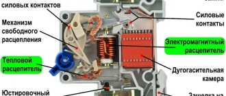
The reversing automatic machine has the form of a box with a built-in blade contact system and spring brackets. When closing the first, metal blades enter the brackets. Thanks to this operating principle, contact rupture under its own weight is eliminated. There is a smooth redistribution of electricity from one line to another.
You can fix the switch on the wall in any position - horizontally, vertically and even diagonally. This does not affect its performance.
Expert opinion
It-Technology, Electrical power and electronics specialist
Ask questions to the “Specialist for modernization of energy generation systems”
Connection diagrams A reversing switch is an excellent solution for safely and error-free load switching from one supply line to another. Ask, I'm in touch!
Requirements for input distribution devices
When supplying power to input distribution devices from overhead lines, surge suppressors must be installed inside them. In accordance with the intended purpose of the ASU, all input supply and output lines must be equipped with protective equipment. Typically, circuit breakers, various types of fuses and other similar devices are used.
Installation of non-automatic switches is allowed in central distribution boards, panels and cabinets. In addition, they can be installed in control devices, for example, in magnetic starters, control stations, etc. They are used for rare manual switching on and off of electrical circuits in which the current does not exceed the nominal value. In some cases, only manual switches are used, provided they have sufficient service life and breaking capacity.
Advantages and disadvantages of switches
- Visibility. The device usually has an open or semi-closed design, which means that its serviceability can be verified visually. Well, since you can clearly see the conductive knives and tires, it will not be difficult to determine in what position the breaker is located.
- Simple design. Almost all such switches, including changeover switches, have an extremely simple design. They are very durable, easy to maintain, and their repair usually does not require high qualifications and is inexpensive.
- High switching power/cost ratio. This is perhaps one of the main advantages of the devices. Some of these devices can switch currents of hundreds of amperes, and are relatively inexpensive.
DIY changeover switch for a generator
What to do if you don’t have a changeover switching device at your disposal? You can do it yourself. More precisely, not to make, but to assemble from well-known and widespread machines. To do this, it is enough to take two machines and secure them on one bar, having first turned one upside down. In order for both devices to switch simultaneously, you need to install a locking bar (orange in the picture). Especially for this purpose, the sliders of all machines have special holes. The switch is ready. All that remains is to make a connection, which is practically no different from connecting a changeover switch.
Unfortunately, it turned out to be a two-position device, but it has a built-in circuit breaker that will trip in case of overload or short circuit.
Of course, the actual scheme for connecting a generator as a backup source will be somewhat more complicated than those given above - in addition to the switch, you will need certain protection, grounding, and metering devices, but there is nothing complicated here:
