Quite often, to build a welding inverter, the main three types of high-frequency converters are used, namely converters connected according to the following circuits: asymmetric or oblique bridge, half-bridge, and full bridge. In this case, resonant converters are subtypes of half-bridge and full-bridge circuits. According to the control system, these devices can be divided into: PWM (pulse width modulation), PFM (frequency control), phase control, and there may also be combinations of all three systems.
All of the above converters have their pros and cons. Let's deal with each one separately.
Half-bridge power supply circuit
In general, voltage converters can be classified according to many criteria and have different circuits and operating principles.
When it comes to a half-bridge circuit, we necessarily mean push-pull pulse voltage converters (PN).
For understanding, here is a classification of the most common converters:
- Transformer (operate at low frequencies);
- Triac or thyristor (combined because the operating principle of the main elements is largely similar);
- Inverter (convert direct voltages into alternating ones);
- Pulse. Derivative options are possible here: Throttle;
- Single-stroke (essentially operating in throttle mode) With a forward-flow circuit;
- With flyback circuit.
- With the output of the middle point of the primary winding (often called Push-Pull or “Push-Pull”);
Two cycles of operation imply excitation of the windings of the pulse transformer in both directions.
One cycle - only in one direction.
All options have their advantages and disadvantages.
Now let's move directly to push-pull power supplies.
For clarity, it is best to present their simplest diagrams.
Rice. 1. The simplest circuits of push-pull power supplies
The operating principle of push-pull PNs is perfectly illustrated by the Push-Pull diagram:
1. The resulting magnetic field in the primary winding excites a current in the secondary. When a positive pulse/oscillation arrives at the output of the first winding, the transistor operates and passes current.
2. When a negative pulse arrives, the second winding with its own transistor is triggered. At this moment, the first transistor and its winding are idle. That is, they change places.
These are two strokes of push-pull work.
But the circuit can be made more complex by using more control switches (transistors). Then you can get by with only one secondary winding, which greatly simplifies the winding of the pulse transformer. This is most clearly seen in the “Bridge” diagram. Both positive and negative oscillations are applied to one winding.
If you replace half of the transistors with capacitors, you get the same “half bridge”. Capacitors act as a smoothing filter and help stabilize the voltage.
Examples of circuit diagrams
The first, quite common option.
Rice. 2. Schematic diagram
The keys are controlled by a timer; here it is built on the basis of the very popular TL-494 PWM controller. In order for the pulses of the low-power generator to become sufficient for power switches VT3 and 4, they are pre-amplified by a cascade of VT1, 2 and transformer TR1.
Current rectification occurs almost at the output of the circuit. Schottky diodes and simple smoothing filters - capacitors - are responsible for this task.
IRFZ34 mosfets can be used as transistors 1 and 2, IRFP460 as transistors 3 and 4.
The main difficulty is pulse transformers. If you want to calculate yours, it is best to use special software.
- First. Each winding has 50 turns of 0.5 mm wire.
- Second. 1 – 110 turns 0.8 mm, 2 – calculated based on the required voltage (1 turn – 2 V), 3 – 12 turns 0.8 mm.
This configuration can provide up to 500W of power. The nominal value is about 300 W.
The second option is more complicated. But here are provided:
- Protection against short circuit and overloads;
- Soft (soft) start;
- Noise filters at input and output.
Rice. 3. Schematic diagram
The IR2153 chip was chosen as the driver here.
Readers' opinions
No comments yet. Your comment will be the first.
You can leave your comment, opinion or question on the above material:
How to configure the inverter
Making a homemade welding inverter is not that difficult, especially since it is an almost completely free product, except for the costs of some parts and materials. But to configure the assembled device, you may need the help of specialists. How can you do this yourself?
Instructions that make it easier to independently set up a welding inverter:
- First, you need to apply mains voltage to the inverter board, after which the unit will begin to emit the characteristic squeak of a pulse transformer. Voltage is also supplied to the cooling fan, this will prevent the structure from overheating and the operation of the device will be much more stable.
- After the power capacitors are fully charged from the network, we need to close the current-limiting resistor in their circuit. To do this, you need to check the operation of the relay, making sure that the voltage across the resistor is zero. Remember, if you connect the inverter without a current-limiting resistor, an explosion may occur!
- The use of such a resistor significantly reduces current surges when the welding machine is connected to a 220-volt network.
- Our inverter is capable of producing current in excess of 100 amperes, this value depends on the specific circuit used in the design. It is not difficult to find out this value using an oscilloscope. It is necessary to measure the frequency of incoming pulses to the transformer; they should be in the ratio of 44 and 66 percent.
- The welding mode is checked directly on the control unit by connecting a voltmeter to the output of the optocoupler amplifier. If the inverter is low-power, the average amplitude voltage should be about 15 volts.
- Then the correct assembly of the output bridge is checked; for this, a voltage of 16 volts is supplied to the inverter input from any suitable power supply. At idle, the unit consumes a current of about 100 mA, this must be taken into account when carrying out control measurements.
- For comparison, you can check the operation of an industrial inverter. Using an oscilloscope, the pulses on both windings are measured; they must correspond to each other.
- Now you need to check the operation of the welding inverter with connected power capacitors. We change the supply voltage from 16 volts to 220 volts, connecting the device directly to the electrical network. Using an oscilloscope connected to the output MOSFET transistors, we monitor the waveform; it should correspond to tests at reduced voltage.
Video: welding inverter under repair.
A welding inverter is a very popular and necessary device in any activity, both in industrial enterprises and in households. In addition, due to the use of a built-in rectifier and current regulator, with the help of such a welding inverter it is possible to achieve better welding results compared to the results that can be achieved when using traditional devices whose transformers are made of electrical steel.
Push-pull half-bridge converter
Let's study the circuit diagram of a push-pull half-bridge converter, which is internationally called “half bridge” (Fig. 1).
Fig.1. Push-pull half-bridge converter
Until voltage is applied to the gates of the transistors, they are closed. The voltage at the midpoint of the capacitive divider, made on capacitors C1 and C2 of the same capacity, is half the direct voltage supplying the converter.
Let's apply an unlocking voltage from the master oscillator to the gate of transistor VT2. Current will flow through the +Uin circuit, capacitor C1, transformer winding TV1, transistor VT2, -Uin. A voltage will arise on the secondary winding of transformer TV1, which will be rectified by the diode assembly VD1 and smoothed by capacitor C3. Transistor VT1 was closed all this time.
Let's apply a blocking voltage to the gate of transistor VT2 and a supporting voltage to the gate of transistor VT1. The current will flow through the +Uin circuit, transistor VT1, transformer winding TV1, capacitor C3, -Uin. On the secondary winding of transformer TV1, a voltage of opposite polarity will appear relative to the previous cycle, which will rectify the diode assembly VD1 and smooth out capacitor C3. Then a constant voltage from capacitor C3 will be applied to the load. Transistor VT2 is closed during the second cycle.
As you can see, current flows through the load during both cycles. The ripple frequency of the output voltage is twice as high as the conversion frequency, which allows the use of smoothing filter capacitor C3 with a small nominal capacitance. The partial hysteresis loop of the magnetic core of the half-bridge converter transformer is close to the limiting hysteresis loop.
While the load is not connected to the SMPS, half of the DC voltage supplying the converter is applied to each capacitor of the capacitive voltage divider. If the capacitance of the voltage divider capacitors is not large enough, then at maximum load during each half-cycle the capacitors will be significantly discharged, and the voltage on them will exceed half the converter supply voltage.
The voltage applied to the primary winding of the pulse transformer of a half-bridge converter can be calculated using the formula:
Where Up is the constant voltage supplying the converter;
Us is the saturation voltage of one key transistor.
The capacitance of each voltage divider capacitor can be calculated using the following formula:
Where C is the capacitance of the capacitor, F;
Iprimarymax – amplitude of the total current through the primary winding of the transformer;
F—conversion frequency, Hz;
ΔUс – change in voltage on the capacitor over the duration of the passage of the full current pulse Iprimary max.
The magnitude of the alternating voltage component applied to the capacitor should not exceed the maximum permissible reference value for a component of a given brand and type. It is important to remember that the rated capacitance of many capacitors is significantly reduced at high frequencies and low ambient temperatures.
Half-bridge converters are widely used with output powers ranging from a few watts to several kilowatts.
The advantage of a half-bridge converter is the low reverse voltage applied to each key transistor in the cutoff state, approximately equal to the constant supply voltage of the converter.
This allows the use of half-bridge converters at high supply voltages. Half-bridge converters can be turned on without load without causing dangerous damage to components. The ripple frequency is equal to twice the conversion frequency.
If the capacitances of the voltage divider capacitors are strictly the same, the key transistors are identical to each other, and the hysteresis loop of the magnetic core material does not contain defects, then we can assume that there is no magnetization of the pulse transformer core. Such a picture is only possible ideally. For example, in a real half-bridge converter, the capacitances of the capacitors in the voltage divider are always different from each other and, therefore, the magnetization reversal of the transformer is asymmetrical. However, the degree of asymmetry is usually much less than in the magnetic cores of transformers of single-cycle converters. One of the simplest ways to reduce the core bias of a half-bridge converter is to include a non-polar capacitor between the pulse transformer and the midpoint of the capacitive voltage divider.
The disadvantages include the presence of two capacitors in the voltage divider, destruction of the SMPS components due to overcurrent in the load in the absence of a protection system, lower efficiency than that achievable in a bridge converter.
Source: Power Supplies Moskatov E.A.
Rezonver: Unique technology of resonant energy conversion
“Rezonver” welding machines, a new product that at one time caused an unprecedented sensation in the world of metal welding, have recently acquired another revolutionary technology.
Rezonver products, which have always been famous for their excellent performance characteristics with minimal dimensions, will now become even smaller and even more powerful. All this became available thanks to the use of a unique method of energy conversion - resonant. The main innovation of this technology is the use of a resonant high-frequency inverter as a current source, which, unlike classical inverters operating on the pulse principle, has a resonant circuit that allows it to transmit sinusoidal current to the power circuits of the converter.
“Rezonver” devices showed the whole world that welding and cutting, which previously seemed to be incomparable processes and radically opposite to each other, can be available in one body, a good ten times smaller in size than the dimensions of two separate welding and metal cutting stations.
Since you get used to good things quickly, everyone who follows welding innovations expects a lot from the new technology. Let's look at what real advantages the method of resonant energy conversion can offer us:
- The efficiency of welding machines made using new technology, in comparison with competitors, is higher on average by 98%;
- The resonant inverter significantly increases the frequency of current conversion (up to 200 kHz);
- Heat loss by the inverter is minimized;
- Absence of electromagnetic compatibility problems with various equipment due to the narrowed spectrum of electromagnetic radiation;
- The possibility of soft switching of the power group, and as a result, an increased lifespan of transistors that are no longer susceptible to stress loads. This makes the device practically not subject to wear, which makes it possible to achieve a record life expectancy of the station;
- The arc in the plasmatron is formed by contact, which allows the resonant inverter to create a constant voltage with optimal current characteristics. The resonator is not afraid of voltage changes and short circuits; it will do its job perfectly even with 160V of incoming current;
- Resonant energy conversion technology allowed the developers to achieve an even greater reduction in the weight of the welding station: what previously seemed to be 2 kilograms has now become a reality.
In general, after numerous consultations with leading experts, and a thorough study of the welding machine market, we can say with complete confidence that at the moment there are simply no real competitors for the product. An important advantage for the company’s reputation is its adequate pricing policy: all devices are manufactured in Russia, which, with an overwhelming superiority in quality and level of technology, makes them, in comparison with foreign competitors, a much more profitable purchase.
The most commonly used high-frequency converters in welding inverters
To build a welding inverter, three types of high-frequency converters are used, namely converters connected according to circuits: asymmetric or oblique bridge, half-bridge, and full bridge. Resonant converters are subtypes of half-bridge and full-bridge circuits.
According to the control system, these devices can be divided into:
— PWM (pulse width modulation);
— PFM (frequency regulation);
Combinations of all three systems may exist.
Types of high frequency converters:
- Half bridge system with PWM
- Resonant half bridge
- Asymmetrical or oblique bridge
- Full bridge with PWM
- Resonance Bridge
- Full bridge with dissipation choke
Half bridge system with PWM
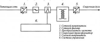
The block diagram is shown below:
One of the simplest and most reliable push-pull converters in the family.
The “surge” of the voltage of the primary winding of the power transformer will be equal to half the supply voltage - this is a drawback of this circuit. But the advantage is that you can use a transformer with a smaller core without fear of entering the saturation zone. For welding inverters with a power of about 2-3 kW, such a power module is quite promising.
For normal operation of power transistors, it is necessary to install drivers. This is due to the fact that when operating in hard switching mode, transistors require a high-quality control signal. It is also necessary to have a current-free pause to prevent the transistors from opening at the same time, otherwise they will fail.
Resonant half bridge
A rather promising view of a half-bridge converter, its circuit is shown below:
The simplicity of a resonant half-bridge in comparison with a half-bridge with PWM is due to the fact that there is a resonant inductance here. It limits the maximum current of transistors, and switching of transistors occurs at zero current or voltage.
The current flowing through the power circuit will have the shape of a sinusoid. This will take the load off the capacitor filters. In this case, drivers are optional. Switching can be done using a pulse transformer. The quality of control pulses is not significant. But there must be a dead pause.
Here you can do without current protection, and the shape of the current-voltage characteristic of the current-voltage characteristic will have a falling form, which does not require its parametric formation.
The output current will be limited only by the magnetizing inductance of the transformer and can reach significant values if a short circuit occurs. This property has a positive effect on the ignition and burning of the arc, but it must be taken into account when selecting output diodes.
The output parameters are adjusted by changing the frequency. But phase regulation is more promising for welding inverters. Thanks to it, you can avoid the unpleasant phenomenon of a short circuit coinciding with resonance. In addition, it increases the range of regulation of output parameters. The use of phase control can allow the output current to be varied in the range from 0 to Imax.
Asymmetrical or “oblique” bridge
This is a single-ended, forward-flow converter, the block diagram of which is shown below:
It is popular among radio amateurs and manufacturers of welding inverters. The first welding inverters were built according to the following schemes - an asymmetric or “oblique” bridge. Their qualities are noise immunity, a wide range of output current regulation, reliability and simplicity.
— rather high currents passing through the transistors;
— increased requirements for the quality of the control impulse. There is a need to use powerful drivers to control transistors;
— high requirements for installation work;
— the presence of large pulse currents, which increases the requirements for capacitor filters.
To maintain normal operation of the transistors, it is necessary to add RCD chains - snubbers.
Despite these disadvantages and the low efficiency of the device according to the circuit, an asymmetric or “oblique” bridge is still used in welding inverters.
Full bridge with PWM
It is a classic push-pull converter, the block diagram of which is shown below:
According to this scheme, it is possible to obtain power 2 times more than when switching on the half-bridge type, and 2 times more than when switching on the “oblique” bridge type, while the magnitudes of the currents and, accordingly, losses in all three cases will be equal. This can be explained by the fact that the supply voltage will be equal to the “drive” voltage of the primary winding of the power transformer.
In order to obtain the same power with a half-bridge (drive voltage 0.5 Usupply), the current required is 2 times! less than for the half-bridge case. In a full bridge circuit with PWM, the transistors will operate alternately - T1, T3 are on, and T2, T4 are off and, accordingly, vice versa when the polarity changes. Through a current transformer, the values of the amplitude current flowing through this diagonal are monitored and controlled. To regulate it, there are two most commonly used methods:
- Leave the cut-off voltage unchanged, and change only the length of the control pulse;
- Change the cut-off voltage level according to data from the current transformer while leaving the duration of the control pulse unchanged;
Both methods can allow changes in the output current within fairly large limits. A full bridge with PWM has the same disadvantages and requirements as a half bridge with PWM.
Resonance Bridge
It is the most promising high-frequency converter circuit for a welding inverter, the block diagram of which is shown below:
A resonant bridge is not much different from a full PWM bridge. The difference is that with a resonant connection, a resonant LC circuit is connected in series with the transformer winding. But its appearance completely changes the process of power transfer. Losses will decrease, efficiency will increase, the load on input electrolytes will decrease and electromagnetic interference will decrease. Drivers should only be used when using MOSFET transistors with gate capacitance greater than 5000 pF. IGBTs can only get by with a pulse transformer.
The output current can be controlled in two ways - frequency and phase.
Full bridge with dissipation choke
The circuit is identical to the circuit of a resonant bridge or half-bridge, only instead of a resonant LC circuit, a non-resonant LC circuit is connected in series with the transformer. Capacitance C, approximately C≈22μF x 63V, works as a balancing capacitor, and the inductive reactance of the inductor L as a reactance, the value of which will change linearly depending on the change in frequency. The converter is controlled by frequency. As the voltage frequency increases, the inductance resistance will increase. And this will reduce the current in the power transformer. Therefore, a fairly large number of industrial inverters are built according to this principle of limiting output parameters.
Welding machine design
Let's look at how to construct a fairly powerful pulsed welding inverter at home.
If you repeat the design according to the Negulyaev system, then the transistors are screwed to the radiator with a plate specially cut for this purpose, thus improving the heat transfer from the transistor to the radiator. Between the radiator and the transistors it is necessary to lay a thermally conductive gasket that does not allow current to pass through. This provides short circuit protection between the two transistors.
The rectifier diodes are attached to a 6 mm thick aluminum plate; the fastening is carried out in the same way as the transistors are fastened. Their outputs are connected to each other with a bare wire with a cross-section of 4 mm. Be careful not to let the wires touch.
The choke is attached to the base of the welding machine with an iron plate, the dimensions of which follow the shape of the choke itself. To reduce vibration, a rubber seal is placed between the throttle and the body.
Video: DIY welding inverter
All power conductors inside the inverter housing must be routed in different directions, otherwise there is a possibility of a short circuit. The fan cools several radiators simultaneously, each of which is dedicated to its own part of the circuit. This design allows you to get by with just one fan installed on the rear wall of the case, which significantly saves space.
To cool a homemade welding inverter, you can use a fan from a computer case; it is optimal in both size and power. Since ventilation of the secondary winding plays a large role, this should be taken into account when positioning it.
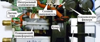
Diagram: disassembled welding inverter
The weight of such an inverter will range from 5 to 10 kg, while its welding current can range from 30 to 160 amperes.
Inverter from computer
Single-phase voltage inverters
The simplest single-phase half-bridge circuit of a voltage inverter with an active-inductive load is presented together with current and voltage diagrams in Fig. 4.2. Let's consider the operation of the circuit assuming the ideality of its elements, as well as input voltage sources with EMF
Let us assume that the inverter operates in steady state and at an interval of 90 - p
current gn is conducted by transistor VT1.
At the moment 9 = l,
a locking pulse is sent to transistor VT1 and an unlocking pulse is sent to transistor VT2.
The latter can begin to conduct current if a direct voltage is applied to it. However, since the current in the inductance Lu
cannot change abruptly, a back-EMF arises in it, under the influence of which the diode
VD2 opens,
through which the inductance current continues to flow.
At the same time, due to a change in the polarity of the voltage across the load, the direction of the current in the active resistance RH abruptly changes.
The resulting load current g'm =
i, + iR,
which is inductive in nature, continues to flow in the same direction through the diode
VD2
to the source
UA/
2, the minus of which is connected to the anode of the diode
VD2.
Since this current flows towards the emf of the source, then at this interval
(k -
9), the process of returning the energy accumulated in the inductance to the voltage source occurs.
At the moment 9 = 9, the current g becomes equal to zero, the diode VD2
closes and the transistor VT2 opens, at the control transition of which there is an unlocking signal, and a forward voltage appears, i.e.
the conditions for its transition to the conducting state are provided. Further, the processes are periodically repeated under the influence of control pulses of the control system, the structure of which is shown in Fig. 4.2, i. In this system, the repetition rate of control pulses is determined by the master oscillator (MG), then through the switchgear (RU) it is supplied to the control pulse formers (FI1 and FI2) of transistors VT1 and VT2.
As a result, a periodic rectangular voltage is formed at the output of the inverter. In this case, current id will flow on the DC side ,
shown in Fig.
4.2, b,
where the “+” sign corresponds to the flow of current into the load, and the “-” sign to the return of part of this current to use
Rice.
4.2. Single-phase half-bridge voltage inverter:
a -
scheme;
b -
work diagrams
exact, i.e. exchange of reactive power accumulated in inductance ?n and its return to the source.
Taking into account the above, we can write down the following basic relationships that determine the parameters of the inverter. Output voltage
when expanded into a harmonic series, it has the form
where 9 = co?; с = 2л:/—angular frequency of voltage;/—switching frequency of transistors.
Instantaneous load current value s
taking into account expression (4.1) can be written as
Balance input RT
and
output
PB1X
active powers:
Average and effective values of currents in diodes VD
1,
VD2
and transistors VT1,
VT2
can be obtained using known relationships, having previously integrated the output current r„ over the intervals (0 - 90) and (90 -l) taking into account current surges at switching moments 9 = 0 and 9 = l.
The more common is a single-phase bridge circuit (Fig. 4.3, a).
Let us consider its operation taking into account previously accepted assumptions with an active-inductive load, in which the inductor
LH
and resistor
RH
are connected across
Rice.
43. Single-phase bridge voltage inverter:
a
- scheme;
b
- work diagrams therefore.
Let's assume that transistors VTI
and
VTA
, the voltage across the load has the polarity indicated without brackets in Fig.
4.3, I, and the load current increases exponentially. At the moment 9 = l
, control pulses arrive, turning off transistors VTI, VT4 and unlocking VT2, V73.
Since the current in
in the load inductance cannot change abruptly, it continues to flow in the same direction, but not through transistors VT1 and
VTA,
but through diodes
VD2
and VD3, which turn on when transistors VT1 and VT4 are turned off due to the occurrence of deflective EMF in the load inductance exceeding the power supply voltage
Ud.
VD2 diodes
and
VD3
leads to a change in the sign of the voltage across the load to the opposite (the polarity indicated in Fig. 4.3,
a
in parentheses).
Under the influence of counter voltage, the load current /n flowing through the diodes VD2
,
VD3
into the power source will also decrease exponentially.
When the current in
to zero (at the moment 9 = 9,) the diodes
VD2
and
VD3
are turned off, and the load current begins to be conducted by transistors
VT2
and VT3, at the control terminals of which there is a control pulse. Then similar processes are repeated periodically.
Thus, a voltage in the form of a meander with amplitude Ud will be formed at the load.
The load current will have an exponential form, and its value will be determined by the load parameters.
Current flows through the diodes at intervals, the beginning of which coincides with the moments of receipt of control pulses, and the duration depends on the load inductance. As current flows through the diodes, energy is returned from the load to the DC source. The absence of diodes in the circuit would lead to unacceptable overvoltages on the transistors. A diagram of the current consumed from a constant voltage source is shown in Fig. 4.3, 6.
In this diagram, positive areas correspond to the release of energy by a constant voltage source, and negative areas to the reception.
In this case, it is convenient to determine the law of change in currents in the circuit using the method of instantaneous values, since the load current does not change its value at the moment of switching. Differential equations for load current in the interval 90 - k
and
k -
9, have the following form:
where the plus sign corresponds to the interval 90 - l, and the minus sign to the interval n -
9,.
Let us write the solution to equation (4.4) in general form:
Integration constant A
is determined from the conditions of continuity of the load current during switching and repeatability of its shape in each period in steady-state operation:
Taking into account the obtained value A
expression (4.5) can be written in the following form:
The average values of the currents of transistors and diodes can be found by integrating equation (4.8) over the intervals E0 - n
and
to -
9,.
According to equation (4.8), the currents in the voltage inverter elements are functions of the load parameters, while in the current inverter the load parameters determine the shape and value of the output voltage. In the circuit under consideration, the output voltage has a rectangular shape with an amplitude equal to the supply voltage Ud.
By expanding the rectangular curve into a harmonic series, we obtain the amplitude of the first harmonic of the output voltage:
From the principle of operation of the inverter in question, it follows that its output voltage does not depend on the load. If the source feeding the voltage inverter has one-way conductivity (for example, a rectifier), then it must be bypassed with a capacitor to receive energy returned from the load.
The “hard” external characteristic of the inverter (dependence of the output voltage on the load) is, in the general case, its positive property. However, there is almost always a need to regulate the output voltage. The simplest way to realize this need is to change the output voltage pulse at intervals of positive and negative half-cycles. This method is similar to the principle of pulse voltage modulation. However, due to the absence of a high-frequency modulation signal, this method is sometimes called pulse-width regulation
(WIDTH), since the change in the output voltage pulse width is made at the fundamental frequency of the output voltage. Let's consider this method using the example of a single-phase bridge circuit.
In the case of an active load, the current shape follows the voltage shape, and pulse-width regulation of the output voltage can be achieved by reducing the duration of the control pulses by an angle a
(Fig. AL, a).
The effective value of the inverter output voltage with this method of controlling transistors and a purely active load will be equal to
Amplitude values of the harmonic components of the output voltage during the duration of the conducting state of the transistors X
=
k - a
are calculated by the formula
where n -
number of the harmonic component
(n =
1, 3, 5.).
In practice, it is often necessary to stabilize the effective value of the first harmonic of the output voltage when the input voltage changes in the range from Udmin
up to
Udmax.
To do this, it is necessary to change the control angle from zero (at
Ud = UdmJ
to amax (at
Ud = Udm
J:
In this case, the harmonic composition of the output voltage will change. As the angle a increases, the relative content of higher harmonics in the output voltage curve will increase.
If the load is active-inductive, then after the transistors are turned off, the current in the load continues to flow for some time, determined by the amount of stored energy in the load inductance,
Rice.
4.4. Pulse-width voltage regulation in a bridge inverter:
a -
voltage diagram with active load;
b -
voltage and current diagrams
with an active-inductive load in the same direction through reverse-connected diodes. When the reverse diodes are turned on, the output voltage changes its sign to the opposite (Fig. 4.4, b).
At the moment the load current decreases to zero, the voltage across the load again becomes zero. The appearance of a negative platform in the output voltage curve will change its harmonic composition. To eliminate this undesirable phenomenon, it is necessary to bypass the load during the pause, for example, using two back-to-back transistors. However, this complicates the scheme. This problem is solved much more simply by changing the control algorithm by implementing pulse modulation (see Chapter 5).
Push-pull boost converter: topology evolution
A large number of boost converters are known, including push-pull ones: a bridge converter with a DC choke at the input, zero topology
Rice. 1. Push-pull half-bridge boost converter: a) original topology; b) basic topology with additional demagnetizing windings of chokes; c) with a common magnetically coupled choke
(push-pull) with a DC choke in the power circuit, etc. The converter considered in this article and its main varieties were proposed in [1]. In foreign literature, it has been given the name two inductor current-fed boost half-bridge converter - a half-bridge boost converter with two chokes at the input and galvanic isolation between the input and output (hereinafter referred to as 2DPPK).
In Fig. Figure 1 shows the main types of 2DPPK. The original topology is shown in Fig. 1a. The primary winding of power transformer Tr1 is powered from “current sources” in the form of DC chokes Dr1 and Dr2. A prerequisite for the normal functioning of the circuit shown in Fig. 1a, is the control of keys VT1, VT2 with a duty cycle D > 0.5.
In other words, a state in which both switches are turned off at the same time must be excluded, since in this case high-voltage voltage pulses occur on the drains of the keys due to the absence of ways for the chokes Dr1 and Dr2 to dump the current accumulated during the closed state of the keys. In practice, the value chosen is Dmin = 0.52–0.55. This topology has the following positive properties:
- In the 2DPPK converter there are fundamentally no through currents between the keys.
- The converter is “not afraid” of saturation of the magnetic circuit of the power transformer - in the case of “magnetization” of the magnetic circuit, each switch switches the currents of both chokes, which increase linearly in time during the switching period. But this process is significantly slower due to the greater inductance of the chokes than with the exponential increase in the magnetizing current of the power transformer when it saturates in converters powered by a voltage source. This circumstance provides the PWM controller with sufficient time to “make a decision” and limit the current through the switches.
- The converter has a high voltage transfer ratio: V0 = 2/(1 – D) × Vinn, where Vin is the converter supply voltage, n is the transformation ratio of the power transformer, V0 is the output voltage.
- The converter provides galvanic isolation between input and output.
In practice, a converter with the original topology can be used either in an regulated mode with D > 0.5, or as an unregulated one with a fixed duty cycle D = 0.52–0.55 and in this form is not of particular interest, but is nevertheless used in as, for example, an input voltage converter for solar panels [2].
It is possible to convert the original 2DPPK version into an adjustable one at a fixed value of D. To do this, a resonant forming circuit is introduced, which makes it possible to use the switching frequency of the switches as a parameter regulating the output voltage. At the same time, it becomes possible to implement the “soft” switching mode of power transistors [2, 3].
To eliminate the main drawback of the original topology - the impossibility of using PWM regulation in a wide range of changes 0 0.5 is possible, but is not considered in this article. Due to the low supply voltage and low output power of the converter, circuits reducing switching losses were not used. In the manufacture of chokes, magnetic cores made of ferrite were used for reasons of convenience of working with a collapsible core. To minimize the weight and size of the chokes, you should use magnetic cores with the maximum available saturation induction, such as Kool-Mu, High Flux, XFlux, Molypermalloy, and powdered iron.
The transformerless version of 2DPPK can also be used at high supply voltages, for example in devices powered from an industrial network of 220 V/50 Hz. In this case, it will be necessary to use high-voltage transistors with a maximum operating voltage of at least 800 V, which can be considered as a disadvantage of this topology. However, this drawback can be overcome by connecting the power transistors in series along the power supply, and not in parallel, as in the basic circuit. An example of such a “high-voltage” 2DPPK with a bridge secondary rectifier is shown in Fig. 9a. In Fig. Figure 9b shows a method of replacing the bridge secondary rectifier with a full-wave rectifier. Diodes VD1 and VD2 in Fig. 9a are recuperative.
Rice. 9. “High-voltage” version 2DPPK with two options for secondary rectifiers
Choose the right solution for your job
Rezonver Hybrid
For the first time, manual arc welding with a consumable electrode and air plasma cutting in one body weighing only 4.5 kg!
Current range 10-180 A PN 96% Weight 4.5 kg
Rezonver Pride
Unprecedented freedom in work and welding quality with a machine weighing 3.5 kg and a maximum current of 180 A.
Current range 10-180A PN 96% Weight 3.5 kg
The most modern technologies for your work
“Rezonver” devices are the latest developments in the field of resonant energy conversion, attention to detail that can facilitate and improve the welder’s work.
What are buyers saying?
Valery Malyutin Auto repair shop owner 08/02/2014
Cool lightweight work machine. I have already ordered four copies from the first batch for each of my masters. The hybrid device is generally a universal machine, very good when you need to quickly cut something and weld it right away. Switches from cutting to welding with one button.
Alexander Malikov Welder V category 08/02/2014
It cooks perfectly in all planes; it cooked both horizontal and ceiling seams without changing power. A very lightweight device, you can solve a variety of technical problems. Pleasant feeling from welding, there are no sharp sounds that irritate in conventional welding machines
Victor Makarov Master of Industrial Training, Educational and Methodological 08/02/2014
Conducted tests of Rezonver equipment. I really liked it. “Pride” is economical and stable in operation in all spatial positions. I also tested the Rezonver Hybrid plasma cutting machine - it’s also an excellent machine.
Welding training
Learning the basics of welding is not that difficult. The main thing is information, desire and advice from an experienced mentor. Comprehensive information and advice on welding for novice welders is presented. Our “Welding Encyclopedia” contains useful books, master classes, hundreds of diagrams and drawings and many video lessons in all areas of this art.