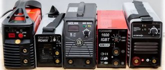
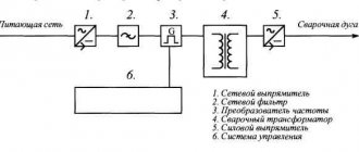
To make homemade DC welders, you will need a high-power power source that converts the rated voltage of a conventional single-phase network and provides a constant value (in amperes) of the appropriate current to directly create and maintain a normal electric arc.
Schemes of a homemade DC welding machine.
{advertisement1}
The high-power power source is a circuit consisting of the following components:
- rectifier;
- inverters;
- current and voltage transformer;
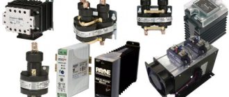
- current and voltage regulators that improve the quality characteristics of the electric arc (thyristors, triacs);
- auxiliary devices.
In fact, based on homemade circuits, the source of the electric arc was and remains a transformer, even if you do not use auxiliary components and circuits of various control units.
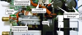
Homemade device: block diagram
Schematic diagram of the power supply of the welding machine.
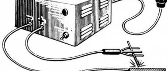
The power supply is inserted into a corresponding box made of plastic or metal. It is supplied with the necessary elements: connecting connectors, various switches, terminals and regulators. The welding machine can be equipped with carrying handles and wheels.
Such a design of fairly good quality welding can be done independently. The main secret of such a device is a minimal understanding of the welding process, the choice of material, as well as skill and patience in the manufacture of this device.
But to assemble the device yourself, you must at least slightly understand and study the basic skills, the moment of occurrence and combustion of the electric arc and the theory of electrode melting. Know the characteristics of welding transformers and their magnetic circuits.
Homemade device: transformer
The basis of any welding device circuit is a transformer that reduces the normal voltage (from 220 V to 45-80 V). It operates in a special arc mode with maximum power. Such transformers simply must withstand very high currents with a nominal value of about 200 A. Their characteristics must be consistent, the I-V characteristic of the transformer must certainly fully comply with special requirements, otherwise it cannot be used for arc welding mode.
Welding machines (their designs) vary greatly. The variety of homemade welding transformers is enormous, because the designs contain a lot of truly unique solutions. In addition, homemade transformers are very simple: they do not contain additional devices designed to directly regulate the current of the structure that flows:
Design of a homemade semi-automatic welding machine.
- using highly specialized regulators;
- by switching a certain number of turns of coils.
The transformer mainly consists of the following elements:
- The magnetic core is metal. It is performed by a set of plates made of transformer steel.
- Windings: primary (network) and secondary (working). They come with leads for adjustment (by switching) or for device circuitry.
When calculating a transformer for the required current, welding is carried out, as a rule, immediately from the working winding, without attaching circuits and various limiting and adjustment elements. The primary winding must be made with terminals and taps. They serve to increase or decrease the current (for example, to adjust the transformer at low network voltage).
The main part of any transformer is its magnetic circuit. In the manufacture of home-made designs, magnetic cores are used from decommissioned stators of electric motors, old television and power transformers. Therefore, there is a huge variety of different magnetic circuits developed by folk craftsmen for such devices.
Parameters (basic):
Welding transformer based on the widely used LATR2 (a).
- magnetic circuit dimensions;
- windings - number of turns;
- input-output voltage level;
- I p - current consumed;
- I max — maximum output current.
Additional characteristics simply cannot be assessed or measured at home, even with the help of instruments. But it is precisely they that determine the suitability of the device’s transformer for forming a high-quality seam when powered in manual welding mode.
This directly depends on how the transformer “holds current” and is called the external current-voltage characteristic (IV-voltage characteristic) of the supply.
CVAC is the dependence of the potentials (U) at the connectors and the welding current, which varies from the load properties of the transformer and from the electric arc.
For manual welding, only a steeply falling characteristic is used, while in automatic welding machines a flat and rigid characteristic is used.
Types of transformers for welding
The technical characteristics of transformers must provide such technical properties that allow heating, melting and joining of processed parts with minimal losses.
The design includes several components:
Transformer core
- A core consisting of several plates made of steel. To assemble the magnetic circuit, plates made of electrical steel are used. One or more windings are installed on it. The voltage is adjusted using a screw pair that passes through the core and winding.
- The metal case is designed to protect the device from any damage. In addition, the transformer includes ventilation devices, handles and wheels for transportation.
The rated operating voltage is 220 or 380 volts and this allows them to be used in industrial facilities and households. The technical characteristics of the transformer allow working with metal workpieces of various shapes and sizes.
The transformer for contact welding consists of the same components as for traditional welding. This equipment operates under short but frequently repeated loads. This results in the windings experiencing severe dynamic loads. To compensate for them, spot welding transformers use an armor-type core and disk windings.
Transformer for contact welding TVK-75
The TVK-75 resistance welding transformer is intended for operation as part of electric welding equipment for spot welding, which are operated indoors under a number of conditions. The magnetic core in this transformer has a tape structure, and is pulled into a frame using studs. The windings of this transformer are disk. For the manufacture of the first winding, heat-resistant PSD cable is used.
Transformer for contact welding TVK-75
The second winding is assembled from separate disks and, using metal parts made of copper, they are assembled into a parallel circuit. To cool the secondary winding, running water is used, which moves through specially laid pipes. The windings are filled with epoxy resin. The voltage is adjusted using switches that are installed on the welding machine. The main parameters of a transformer of this brand include the following:
Cooled with water, the device is manufactured according to insulation class F. Due to the use of Unicore technology, the transformer suffers minimal losses in the magnetic circuit. The manufacturer produces a transformer in the UHL4 climatic version.
Transformer for resistance welding TKS - 4500 Cascade
Transformer for resistance welding TKS - 4500 Cascade is used for welding parts made of low-carbon steels with a total thickness of up to 4 mm.
Calculation of a transformer for welding
The magnetic core and windings are responsible for creating the operating parameters of the device. That is, knowing what characteristics a transformer should have, you can calculate the parameters of the windings, core and cross-section of all wires.
To perform calculations, you need to take the following data:
DIY welding transformer
- Voltage on the first winding.
- Voltage on the second winding.
- Current strength on the second winding. The size of this parameter is determined by the type of electrodes and the dimensions of the workpiece.
- Core area. This parameter determines the reliability of the transformer as a whole. The optimal size can be considered from 45 to 55 square meters. cm.
- Core window area size. The optimal size is considered to be from 80 to 110 square meters. cm.
- Current density inside the winding. This parameter is responsible for the losses in the winding. For do-it-yourself devices, this characteristic is 2.5 - 3 A.
Welding machine: arc characteristic
An arc is an electrical discharge that flows for several minutes between an electrode (positive or phase terminal) and ground (negative terminal). Metal placed in this zone heats up and melts. When an arc occurs, a breakdown of the gas in the interelectronic region occurs, and when the arc process stabilizes, ion conductivity appears. The stabilizer of a normal arc is considered to be the top layer of the electrode, the so-called coating, which evaporates during welding.
In the process of joining metals with an electrode, under the influence of high temperatures, the metal is directly melted, followed by the formation of a drop, and then its transfer from the electrode to the structure. The occurrence, formation and diameter of droplets, as well as the speed of their appearance, mainly depend on the length of the electric arc, the parameters of the electrode and the current strength.
If the system works normally, the metal is welded smoothly, and the arc is stable, then everything is done perfectly. If not, then the current-voltage characteristic of the system is rigid. This can be corrected by turning on a ballast resistor with a value of less than 1 Ohm (part of a nichrome wire). Such a resistor will limit the I max of the transformer (maximum current) and straighten its VA characteristic.
This way it is possible to obtain good results of a normal arc during manual welding. Improving the slope of the VA characteristic can be achieved by increasing the no-load (output voltage) at the expense of reducing the efficiency of the system.
Power block
The basis of the power unit of the welding inverter is a transformer, due to which the voltage of the high-frequency current is reduced and its strength is increased. In order to make a transformer for such a block, it is necessary to select two Ш20x208 2000 nm cores. You can use newsprint to provide a gap between them.
To ensure thermal insulation, each layer is wrapped with cash register tape, which demonstrates good wear resistance. The secondary winding of the transformer is formed from three layers of copper strips, which are insulated with each other using fluoroplastic tape. The characteristics of the transformer windings must correspond to the following parameters: 12 turns x 4 turns, 10 sq. mm x 30 sq. mm.
Many people try to make the windings of a step-down transformer from thick copper wire, but this is the wrong solution. Such a transformer operates on high-frequency currents, which are forced onto the surface of the conductor without heating its interior. That is why the best option for forming windings is a conductor with a large surface area, that is, a wide copper strip.
Homemade inverter output choke
Plain paper can also be used as a thermal insulation material, but it is less wear-resistant than cash register tape. This tape will darken due to elevated temperatures, but its wear resistance will not be affected by this.
Dynamic response
Schematic diagram of a bridge rectifier for a welding machine.
Another useful technical parameter characterizing the operation of the device is the dynamic characteristic (DC) of your power supply, which must have a quick response to changes in the electrical parameters of the arc (current, voltage). This depends on the time it takes for the voltage to recover from zero readings in short circuit mode to the arc reappearance voltage.
This time is the DH of the power supply. It should not be more than 25 Volts/0.05 seconds. This dynamic effect occurs when the hot metal is short-circuited to the part, at the moment the transformer goes into short-circuited mode. In this case, the short-circuit current strength in the secondary winding can reach double the value, and welding machines for manual welding, due to this ratio, can have a negative factor.
For stable burning of a welding arc, the so-called elasticity of the arc has an important property. It continues to burn as its length increases. The elasticity of the arc is a quantitative value; its criterion is its maximum length at which the arc is capable of existing.
The arc ignites only when the required voltage is reached in the initial half-cycle. The alternating current arc goes out and lights up 100 times/sec with separate flashes. This can be changed by the open circuit potential and the phase shift between the open circuit potential and the arc current. You can reduce pauses in the duration of electric arc burning by increasing the idle potential.
But it is not recommended (due to electrical safety) to increase it above 80 V. This can be solved by using circuitry, for example, by turning on inductors that create a phase shift in voltage and current. The electric arc, after modification, maintained by self-induction, may not be interrupted.
Hello. What if the transformer is W-shaped? Can you advise? I'm assembling a welding machine.
Hello, Alexander. The operating principle is the same. However, send photos to the site’s email (see section “About the site”) and describe the dimensions of the magnetic core iron. This will help me make a power calculation. Also read the comments to the article about the design of the homemade Moment soldering iron. There I devoted a lot of time to this issue. You will need it.
Read also: Homemade ax made from springs
Hello Dear Alexey! Thank you for your article, very useful and interesting! Tell me, I have a couple of questions! My initial power source is already ready 36 volts DC, if I exclude the very beginning of the so-called transformer from this circuit, will this circuit work? Or is it not suitable for me? Need something else? I'll be looking forward to your answer! thank you in advance!
Hello, Pavel. I didn't quite understand your question. Let's clarify: you have a ready-made voltage source that gives an output of 36 volts. Did I understand correctly that you want to use it to make a DC welder? For reliable arc ignition you need 60-70 volts. In my case, it turned out to light it from 50. I didn’t experiment below, try it, but it’s unlikely that you’ll get anything good... One more important electrical characteristic is the output power. If this is not provided, the welding machine will simply burn out. I created it at 50Vx160A=8kW. Pay attention to the power circuits of your source, will they withstand such power? Actually, I advise you to do the calculation based on the initial problem: what electrodes are you going to use to cook and cut. It is necessary to create an electric arc current under them and ignite it. This will determine the output power of the welder. The design is calculated and parts are selected based on these parameters. Send us a photo of your unit. Or better yet, a diagram. Then it will be possible to give more specific recommendations.
Victor, the ignition voltage depends on the characteristics of the welding electrode. With the right choice of electrode, welding work goes well at Ux.x. welder 36 volts or less.
Thanks for the addition. Alexander. Pavel has already explained this to me too. I'm just not a welder, but a simple electrician.
I work as a welder in the north, I travel urgently to emergency situations! Situations often began to occur when the welding generator needed to be dragged directly into the swamp or to perform certain welding jobs - this was very difficult and sometimes extremely impracticable! But I go to the site on a tracked all-terrain vehicle with 24 volt batteries installed. It is not difficult to remove them and quickly bring them to the place! 24 volts does not cook well, but when connecting the battery. up to 36 volts cooks perfectly! but last week a situation happened that I tried to weld the break for too long and my battery exploded! Dear Alexey, I ask you to help me in this matter because after reading your article I realized that you are a professional in this matter! Is it possible to adjust your circuit to 36 volts DC, or 24 if necessary, I can connect two to 48 volts
Well, I use 2.0 and 2.5 mm electrodes, sometimes I use 3 mm. current for them from 70 to 110 amperes for the eyes 36 volts cooks well, well, more precisely, it cooked! As you understand, it was shorted to a straight line! I understand that, of course, this is nonsense and everything should be correct and according to science! That's why I turned to you! 110 is even a lot, rarely when I set it to more than 100 it means 70-100 amperes
Pavel, doing welding from a battery assembly is not the best option, but it works quite well for emergency situations. We must take into account the risk of losing the battery. What needs to be taken into account in my opinion: 1. All banks must be well charged. Any defective bank will work to discharge the battery, taking its current onto itself. 2. Welding must be done quickly. Otherwise, the electrolyte will boil and the battery will explode. Before my eyes, while serving in the army, a mechanic driver of a self-propelled tractor dropped a wrench about 22x24 in size onto the battery output tires. The arc was such that the key burned out, but the banks survived. They started a diesel engine with 500 horses. I don’t remember the amps, but the assembly was made from tank batteries. It was difficult to drag them even with two people. I return to our welding. We assume that the maximum current should be 110 amperes. It should be issued by the battery. A voltage of 48 volts should be sufficient. If you worked from 36, then you can also use it, but 48 is better. The mode of short circuiting batteries through the electrode is not very good. It must be limited by electrical resistance. For DC circuits, I recommend using a CMOS series bipolar transistor. The control circuit that I made for a welder using rectified current will not work. Here it is pure constant and everything works differently. I’ll think about the scheme tomorrow and propose something that, in my opinion, is most suitable.
Pavel, I haven’t found a decent circuit that a beginner with minimal electronics skills can assemble. Many mistakes can be made. I propose to connect an inverter to the battery, converting constant voltage into 220 volts, and power the welding inverter from it. All this equipment can be simply purchased. The heating of the electrolyte in batteries must be controlled; it must not be allowed to boil.
Good day Pavel, I have such a device as ISKRA Universal vd 0801 knot. I encountered this factor while working. During operation, it buzzed very loudly and the diodes flew out. I replaced all 16 diodes with new ones. turned it on and inserted the jumper into the block. and everything happened again. what could be the problem. There is very little said on the Internet about such a device, maybe you can help. thank you in advance
Hello, Ivan. I have not encountered such a device, there is no diagram. What I found on the Internet raises doubts and requires verification. However, we have experience with repairing such devices. I think we'll repair it. I need a diagram and detailed photos. Send what you have to the site's email. I will get acquainted with the design and tell you what to do. You will need a multimeter or an old tester for electrical measurements. Battery, flashlight bulb. wires. I'm waiting for additional information.
Possible details and calculations
Scheme of an inverter welding machine.
At a constant potential, the electric arc is characterized by high stability and quality of seams. Direct current in homemade devices occurs when high-power rectifiers are used. For example, made using diodes with a current of 200 A - B-200.
Their large sizes and the mandatory use of radiators for effective heat transfer determine the design parameters. It is possible, and even in some cases better, if you use a special diode bridge. Moreover, they can be paralleled, thereby increasing the output current.
The voltage waveform is smoothed by an "electrolyte" of 10,000 µF or more, connected through a resistor. It is necessary to prevent the occurrence of a short circuit at the moment of arc ignition, when the electrode touches the welded parts.
The peculiarity of the calculations is that when assembling a homemade device with your own hands, you have to adjust all the parameters to the available parts, which very often are not of the best quality. For example, they use a magnetic core from a weak transformer or use the stator of an old rusty engine.
All this affects the quality of welding. But, despite this, many craftsmen create truly unique home-made devices that have a soft ignition of the electric arc, weld parts with thin walls and almost do not splash pieces of metal.
Methods for adjusting current
There are many ways to regulate the current, and above we wrote about the secondary and primary windings. In fact, this is a very rough classification, since the adjustment is still divided into several components. We will not be able to analyze all the components within the framework of this article, so we will focus on the most popular ones.
One of the most commonly used current control methods is to add a ballast at the output of the secondary winding. This is a reliable and durable method; you can easily make a ballast with your own hands and use it without additional equipment. Often, ballasts are used solely to reduce current.
In this article, we described in detail the operating principle and features of using a ballast for a semi-automatic welding machine. There you will find detailed instructions on how to make the device at home and how to use it in your work.
Despite many advantages, the method of adjusting the current through the secondary winding when used in conjunction with a welding transformer may not be very convenient, especially for novice welders. First of all, the ballast is quite bulky and its size can reach a meter in length. The device is also often underfoot and gets very hot, and this is a gross violation of safety regulations.
If you are not ready to put up with these shortcomings, then we recommend that you pay attention to the method when the welding current is adjusted through the primary winding. For these purposes, electronic devices that can be easily made with your own hands are often used. Such a device will easily regulate the current through the primary and will not cause inconvenience to the welder during operation.
The electronic regulator will become an indispensable assistant for a summer resident who is forced to weld under conditions of unstable voltage. Often houses are simply not allowed to use electrical appliances larger than 3-5 kW, and this is very limiting in their work. Using the regulator, you can configure your device so that it can operate smoothly even with low voltage. Also, such a device will be useful for craftsmen who need to constantly move from place to place while working. After all, the regulator does not need to be dragged around like a ballast, and it will never cause injury.
Now we will talk about how to make an electronic regulator from thyristors yourself.
Schematic diagram
Package of transformer iron (magnetic core).
Based on the above, different designs were tried, with transistor and thyristor control, which led to the present circuit.
It turned out that thyristors are more reliable. They can easily withstand any short circuit at the output and quickly recover from this state. They do not need a powerful radiator, since the heat dissipation is much less. Transistors quickly fail when overloaded and are very capricious in the selection of parameters.
The scheme is not as original as it might seem. But it is distinguished by its simplicity and reliability, easy availability of parts and speed of setup. This is a converter assembled from elements of a “soviet” TV. His details are:
- adjustment - smooth;
- current is constant.
When welding 3 mm steel with a 3 mm caliber electrode, the current consumption is about 10 A, and the welding voltage is obtained by pressing the button on the plug holding the electrode. It helps:
- Increase safety, because when the button is pressed, there is no voltage on it.
- Work with increased arc voltage to ensure arc combustion.
- When the reverse polarity voltage is turned on, it becomes possible to weld very thin parts.
Welding circuit operation:
Block – diagram of a welding inverter.
- The network bridge VD1-VD4 rectifies the alternating potential of the network.
- Current begins to flow through the contacts of lamp HL1, which acts as an indicator of the entire process, charging the “electrolyte” C5. HL1 also limits the device's charging current. As soon as it goes out, you can weld the parts.
- When charging C5 starts, the bank of capacitors C6-C17 is charged through the inductor circuit L1. The HL2 LED lights up and indicates that the device is receiving mains voltage. But no welding occurs - thyristor VS1 is closed. There is no potential at its control pin.
- When the SB1 button is turned on, the voltage goes to a pulse generator with a frequency of 25 kHz, which is made according to the 3USTS TV circuit using a VT1 (single-junction) transistor.
- The pulses of this generator enter the thyristor VS2, starting it, and it opens the parallel thyristors VS3-VS7.
- “Electrolytes” C6-C17 begin to discharge through the “I” winding of transformer T1 and the inductor circuit L2. This entire circuit - T1, C6-C17 and inductor L2 is an oscillating circuit with varying current. When the circuit is in antiphase, the current flows through diodes VD8, VD9. Paralleled (VS3-VS7) thyristors are turned off and wait for a new node pulse on VT1. After this everything repeats itself.
- Pulses appear on the transformer (on winding “III”) that unlock VS1. And through it, the rectifier VD1-VD4 is connected to a thyristor converter.
An HL3 LED is installed to indicate the generator is starting. To rectify the welding voltage, VD11-VD34 are installed. And to smooth out the shape of the curve and facilitate the occurrence of an electric arc, “electrolytes” C19-C24 are used.
Reliable welding current control circuit
The work involves three blocks:
- stabilized voltage;
- formation of high-frequency pulses;
- separation of pulses into circuits of thyristor control electrodes.
Voltage stabilization
An additional transformer with an output voltage of about 30 V is connected from the power winding of the 220 volt transformer. It is rectified by a diode bridge based on D226D and stabilized by two zener diodes D814V.
In principle, any power supply with similar electrical characteristics of current and output voltage can work here.
Pulse block
The stabilized voltage is smoothed by capacitor C1 and supplied to the pulse transformer through two bipolar transistors of direct and reverse polarity KT315 and KT203A.
Transistors generate pulses to the primary winding Tr2. This is a toroidal type pulse transformer. It is made of permalloy, although a ferrite ring can also be used.
Winding of three windings was carried out simultaneously with three pieces of wire with a diameter of 0.2 mm. Made 50 turns. The polarity of their inclusion matters. It is shown by dots in the diagram. The voltage on each output circuit is about 4 volts.
Windings II and III are included in the control circuit for power thyristors VS1, VS2. Their current is limited by resistors R7 and R8, and part of the harmonic is cut off by diodes VD7, VD8. We checked the appearance of the pulses with an oscilloscope.
In this chain, the resistors must be selected for the voltage of the pulse generator so that its current reliably controls the operation of each thyristor.
The unlocking current is 200 mA, and the unlocking voltage is 3.5 volts.
Welding current regulation
Variable resistor R2, with its resistance, determines the position of each pulse passed through the control electrode of the thyristor. The shape of the pulsating current at the output of the power circuit of the welding machine depends on it.
Half-sine ripples can pass through completely when the welding current is set to maximum or be cut off to almost zero.
Design of transformer and chokes
Wire winding diagram.
T1 is assembled from 3 “lines” from old TVs, folded together. Core PK30x16 made of ferrite grade 3000NMS-1. Windings “I” and “II” each have 2 sections with PSD 1.68 wire insulated with fiberglass. They are connected in series and have turns:
- winding “I” - 2×4;
- winding “II” - 2×2.
Winding “I” operates in the worst thermal conditions, so during assembly it is necessary to wind it with a pitch (gap) of 1 mm. In the second winding, do not forget to tap from the middle.
Both windings must be placed in such a way that the operation of the diodes VD11-VD34 is not disrupted. The winding direction of winding “I”, starting from the terminal connected to L2, is counterclockwise. And the winding direction of winding “II” is clockwise, from the terminal connected to VD21-VD34.
https://moyakovka.ru/youtu.be/dgoFznbxQPs
{advertisement2}
Winding “III” is a turn of wire 0.4-0.5 mm in insulation for a voltage of 500 V or more.
It is important to distribute the windings, maintaining the gaps correctly. This is necessary for cooling the magnetic circuit and for safety reasons. To do this, install 4 fiberglass (1.5 mm) plates, which are glued after adjustment.
Inductor L1, with an inductance of 40±10 μH, is wound on a PL core 12.5×25-50 with a gap (non-magnetic) of 0.3-0.5 mm and has 175 turns wound with PEV-2 type wire, caliber 1.32.
Choke L2 is a spiral without a frame, wound with 4 mm2 wire in thermal insulation. Number of turns -11, winding diameter -14 mm. A large current flows through the inductor and it needs to be blown through.
https://moyakovka.ru/www.youtube.com/watch?v=co6SUTVGqOs
Device design
The VD11-VD34 rectifier is a shelf made of aluminum, secured with studs. Every two diodes are sandwiched between 1 mm plates with dimensions of 44x42 mm.
Transistor VT1, “conders” C2-C4 and C6-C18, thyristors VS2-VS7, zener diodes and diodes VD5-VD7, VD8-VD10 and resistors are installed on a fiberglass board.
Parts and materials of the welding device:
Assembly diagram of a welding machine transformer.
- SA1 is a batch switch. Current 16 A or more.
- VN-2 - fan (indicated in the diagram as M1).
- C1 - voltage 220 V or more.
- VD1-VD4 - diodes rated at 16 A or more, installed on 2 mm radiators with an area of 900 mm2.
- “Electrolyte” C5 can be composed of several. Voltage 400V or more.
- C6-C24 with a voltage of 1000 V or more must have a dielectrically small loss angle, for example K78-2 or imported film ones.
- VS2-VS7 - KU221 A thyristors. Due to high currents and heating of the thyristor cathodes, it is advisable to put copper foil caps on them. All thyristors are installed on a common 3 mm radiator plate.
- VD8-VD9 - diodes KD213A (B, B) or KD2997A (B), installed on a radiator with thyristors. VD9 is based on a mica insulator.
- R14-R18 - resistors grade C5-16 V or more powerful.
- Screws, nuts, washers.
- Rivets.
- Aluminum plates.
https://moyakovka.ru/youtu.be/LvIyLUOzS64