Question:
Answer:
It all depends on what you mean by “check the welding transformer.”
If you are interested in how to check the functionality of the device when purchasing, then we can say that there may not be too many verification manipulations. First, turn on the device and listen to the sound of its operation. The welding transformer should not hum too much. We are not talking about the fact that all indicators (if any) and other “signs of life” of the device should turn on; this is already clear by default. If possible, it would be a good idea to check whether the primary winding does not penetrate the housing and other important parts of the welding machine. However, such things can only happen if you purchase equipment from unknown manufacturers who have not earned a reputation in the market. Be that as it may, be sure to buy only those devices that come with a warranty. By the way, in our store absolutely all welding equipment is accompanied by a warranty card.
If you have some kind of malfunction, then in this situation it is worth considering the following: a welding transformer is an extremely simple equipment and the causes of the malfunction can often be detected without specialized testing. For example, noticeable heating of the device indicates either a short circuit in the primary winding or poor contact of the connections.
If your transformer produces a welding current that is too high and does not coincide with the value set on the scale, then this problem indicates the presence of a short circuit either in the winding of the current regulator or in the secondary winding of the transformer. There are also situations when the welding current cannot be adjusted by turning the control knob. This indicates a short circuit or malfunction in the regulator terminals. Well, then you will have to pick up a tester, measure resistance and other indicators and fix any problems that arise.
We strongly discourage you from fixing breakdowns yourself. This can lead to even more breakdowns and problems. In some cases, “self-medication” leads to the fact that you have to throw away the welding transformer and buy a new one. If your warranty period has expired, it is better to contact qualified specialists who will repair the device quickly, efficiently and inexpensively. The cost of repairing tools such as welding transformers is rarely high, since the circuitry of this equipment is surprisingly simple and easy to repair. Well, if the warranty is still valid, then it is even better not to look into the device yourself, so as not to lose the right to free warranty service.
When coming to a store or looking at online portals, the buyer first of all looks at the price tag of the equipment presented, naturally looking for an option that would be optimal in terms of cost and quality ratio.
At the same time, price is not always an objective selection criterion. It is in the lowest price category that there is a huge layer of low-quality goods. In this article we will talk about technologies that are used to deceive buyers.
Let's start with the simplest:
Overestimation of current characteristics
Often the numbers indicated on devices, in instructions or on equipment boxes have nothing to do with reality. It happens that the promised and actual values of the welding current differ by 20 or even 50%. For example, instead of the declared 200A, the device produces only 125.
When choosing a welding machine, the buyer looks at the upper limit of the welding current and compares the price with competitors based on their technical characteristics. As you understand, the cost of 120 and 200A devices differs significantly in favor of the first, and you are offered to pay for it as for a much more powerful device.
A professional never buys a welding machine with the current characteristics that he needs, i.e. If a welding specialist needs a 180A current source, then in the store he will opt for a 200 - 250A inverter. This choice, on the one hand, protects the buyer from underestimating the characteristics, on the other hand, allows you to have a reserve of power.
The manufacturer, knowing about this feature of the choice, periodically overestimates the current characteristics. As a result, the power reserve that the buyer expects to receive turns out to be zero, but the allegedly “200A” device costs a little more than the 180A analogue.
Diagnosis of inverter faults
Immediately before restoring the functionality of inverter welding equipment, you should familiarize yourself with typical faults and the most effective diagnostic methods.
In most cases, repair of semi-automatic welding machines should be carried out according to the following algorithm:
- Visual inspection of all inverter components.
- Cleaning oxidized contacts using a solvent and a brush.
- Studying the design of the inverter using the documentation included in the kit.
- Fault diagnosis.
- Replacement of non-working electronic components.
- Test run.
All malfunctions that may require DIY repair of welding machines are divided into three types:
- arising due to incorrect choice of welding mode;
- arising due to a malfunction of one of the elements of the electronic circuit of the device;
- caused by dust or foreign objects entering the housing of the inverter power supply.
Before checking the welding machine for faulty radio components, you should completely clean it of dust and dirt. Clogging of the cooling elements of the arc support system can adversely affect the performance of many electronic components.
If a preliminary visual check does not reveal any malfunctions, then you should proceed to a more in-depth diagnosis.
Typical reasons for inverter failure are presented:
- liquid entering the inverter housing, resulting in oxidation of the conductive paths and corrosion of the main radio elements;
- an abundance of dust and dirt inside the case, as a result of which the cooling significantly deteriorated and the power microcircuits overheated;
- overheating of the inverter due to the selection of an incorrect operating mode, which may require repair of welding rectifiers.
Repairing a welding transformer, unlike an inverter, can be performed without significant skills and abilities. Transformer assemblies use radioelements that have an incredibly long life cycle.
The repair technique for the converter and other key components of the inverter current source will be shown in the next section.
How does a welding inverter work?
The formation of a high current, with the help of which an electric arc is created to melt the edges of the parts being joined and the filler material, is what any welding machine is designed for. For the same purposes, an inverter apparatus is also needed, which allows the generation of welding current with a wide range of characteristics.
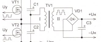
In its simplest form, the principle of operation of the inverter looks like this.
- Alternating current with a frequency of 50 Hz from a regular electrical network is supplied to the rectifier, where it is converted into direct current.
- After the rectifier, the direct current is smoothed using a special filter.
- From the filter, direct current flows directly to the inverter, whose task is to convert it again into alternating current, but at a higher frequency.
- After this, using a transformer, the voltage of the alternating high-frequency current is reduced, which makes it possible to increase its strength.
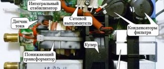
Block diagram of an inverter type welding machine
In order to understand the importance of each element of the electrical circuit diagram of an inverter device, it is worth considering its operation in more detail.
Main types of breakdowns and their elimination
Before considering the main types of malfunctions of inverter devices, you should familiarize yourself with the inverter device.
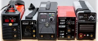
Most popular models consist of:
- power supply;
- control unit;
- power block.
Malfunctions and repairs of welding machines in most cases are associated with a breakdown of the power unit, consisting of:
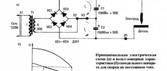
- Primary and secondary rectifiers. The block includes two diode bridges of varying power. The first bridge is capable of withstanding up to 40 amperes of current and up to 250 volts of voltage. The second diode bridge is assembled from more powerful elements and is capable of maintaining a current of 250 amperes at a voltage of about 100 volts. Possible errors of this module are associated with failure of the diodes of the primary or secondary bridge.
- Inverter converter. A breakdown of the power transistor of the inverter converter is often the answer to the question why the welding machine does not weld. The inverter can be repaired by replacing the transistor with an analogue one with a current rating of 32 amperes and a voltage of 400 volts.
- High frequency transformer. Typically, a transformer consists of several windings that increase the current to 250 amperes at a voltage of up to 40 volts. Most inverter equipment has two windings made using copper wire or tape.
Before you repair welding machines with your own hands, you should carefully diagnose the device and clearly determine which of the elements is faulty.
You shouldn’t even try to repair an inverter yourself from which thick white smoke is pouring out of the housing. In such cases, the best solution would be to contact a qualified repair center.
Repair of a semi-automatic welding machine with an inverter source may be necessary if the following malfunctions occur:
- Unstable burning of a hot arc or strong spattering of the electrode material. The malfunction in most cases is due to the incorrect choice of operating current. The operating instructions say that per 1 millimeter of electrode diameter there should be a current of 20 to 40 amperes.
- Adhesion of welding to metal. This behavior is typical for devices operating at insufficient voltage. Such malfunctions and methods for eliminating them are clearly described in the accompanying documentation. If the electrode sticks to the material being welded, clean the terminal contacts to which the inverter device modules are connected. In addition, it would not be superfluous to measure the voltage in the electrical network.
- No arc when turning on the equipment. The defect is often associated with simple overheating of the device or damage to the power cables during long-term operation at elevated temperatures.
- Inverter emergency shutdown. If during the work the device suddenly turns off, then the short circuit protection between the wires and the housing has probably worked. Repairing the device in the event of such a defect consists of finding and replacing damaged elements of the inverter power circuit.
- Huge consumption of electric current during idle operation. A typical malfunction that occurs due to the short circuit of the turns on the current-carrying coils. Restoring the device's functionality after such a malfunction consists of completely rewinding the coils and applying a layer of additional insulation.
- Switching off welding equipment after a certain period of time. This behavior is typical for overheating inverter electrical appliances. If the welding suddenly turns off, then you need to let it cool down and after 30-40 minutes you can continue working.
- Extraneous sounds when the power supply is operating. Elimination of the defect consists of tightening the bolts holding together the magnetic guide elements. In addition, the malfunction may be due to a defect in the core fastener or a short circuit between the cables.
Everything with your own hands
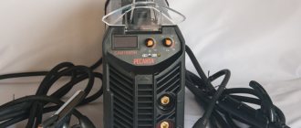
Hello, friends. A couple of days ago they gave me the control unit for the feed mechanism of a semi-automatic machine. He actually used spare parts for another device, but the case with measuring instruments was perfect for a load resistor for testing DC welding machines, so far only DC.
Quite a useful device for determining the real characteristics of welding inverters. I have long dreamed of finding out what current my welding Procraft AWH-285 has, I can’t believe it’s 285A
This is what the control unit looks like. Managed the Granit ZUZ wire feed unit. One worker, the second went to spare parts
And this is what it looks like inside, the one I got for spare parts
Here is such a solid 500A shunt Two measuring heads Ammeter 500A and Voltmeter 75V
I made three springs from knitting wire with a diameter of 1.5 mm on a 35 mm mandrel, 27 turns each. This is approximately 3m of wire. I connected everything with an M8 pin.
The mandrel is a pipe with a slot along it. The edge of the wire is fixed in this slot and I twist the pipe, holding the wire so that it fits more tightly turn to turn. Then, during installation, the spring itself stretched as much as necessary.
I connected the minus with a copper busbar, and the plus with a flexible connection from a 50mm sq. welding cable.
I decided to check the welder and the welder at the same time and this is the picture, voltage 8V, current 80A
Apparently there is not enough resistance, only 0.07 Ohm, so I connected 3 more of the same springs in series.
And he connected the blocks with an aluminum bus of a very large cross-section, this is a flattened pipe.
But as it turned out, my device can only output 80A, but the indicator shows 295A. I bought it a year ago for 4,500 rubles on the local market. I was counting on at least 160. I thought he didn’t really cook, but what’s the matter is 80A in total
As a result, after playing around a little, I configured my device to 120A, and also configured the indicator. A good example of applying a load. Trusting the indicators and knowing Ohm's law, the resistance of the resistor is 0.19 Ohm. And this is because the wire has heated up and the resistance has increased.
I’ll tell you about setting up my Chinese welding in the article Setting up and honest characteristics of the ProCraft AWH-285, but I’m very pleased with the load. Although the springs get hot, they never turn red during 3 minutes of load. I think up to 200A can be loaded.
I’m still thinking about the cover, as well as about the welding connection cable. And if you like my ideas, subscribe to updates in VKontakte or Odnoklassniki groups and always be aware of the latest updates.
Good luck to everyone with the repairs. With uv. Edward
Dear readers. The fact is that assembling my projects takes a lot of time, it’s unforgivable that I withhold a lot of money from the family budget and I won’t do it anymore. If you like what I’m doing here and want to continue, then I ask for your support. There will be support, there will be a lot of new things (drawings and diagrams are already there). You can support here
Recommendations for DIY repairs
When repairing inverter-type welding machines, you should adhere to a certain algorithm:
- If a malfunction occurs, you must immediately disconnect the electrical device from the network, allow it to cool, and only then open the metal casing.
- Diagnostics must begin with a visual inspection of the electrical components of the inverter. There are often cases when repairing an inverter welding machine involves simply replacing damaged parts or soldering conductive contacts. Visually enlarged capacitors or cracked transistors should be replaced first.
- If a visual inspection fails to determine the cause of the malfunction of the welding machine, you must proceed to checking the parameters of the parts using a multimeter, voltmeter and oscilloscope. The most common failures of power units are associated with malfunction of transistors.
- After replacing the electrical elements, it is worth moving on to checking the printed conductors located on the inverter board. If you find torn or damaged tracks on the printed circuit board of a welding tool, you must immediately eliminate the defect by soldering jumpers or restoring the tracks using copper wire of the required cross-section.
- After completing work with the tracks, it makes sense to move on to servicing the connectors. If the inverter device stopped working gradually, then there may be poor contact in the connecting connectors. In this case, it is enough to measure all contacts with a multimeter and clean the connectors with an ordinary household eraser.
- Despite the fact that malfunctions of a welding inverter are rarely associated with diode bridges, it would be a good idea to check their performance. It is better to diagnose this electrical element in a soldered state. If all the legs of the bridge are short-circuited, then you should search for the faulty diode and replace it.
- The last step in inverter repair is checking the board and control panels. Diagnostics of all components of the board should be carried out using a high-resolution oscilloscope.
When performing independent repair work, you should not forget about the safety rules:
- Do not use electrical appliances without a protective top casing;
- all diagnostic and repair work should be carried out on completely de-energized equipment;
- It is safest to remove accumulated dust and dirt using an air flow generated by a compressor or a compressed gas cylinder;
- Cleaning of printed circuit boards must be done using neutral solvents applied to a special brush;
- Long-term storage of electrical appliances should be done in dry rooms and completely switched off.
Most inverter electrical appliances are supplied complete with accompanying documentation. In these papers you can find a description of the most common faults and repair methods. Therefore, if malfunctions occur, you should carefully study the documentation and only then begin repair work.
Features of repair of inverter welding machines
In recent years, inverter welding machines have gained popularity. This technique is relatively inexpensive, easy to use, and allows you to perform most jobs. At least in everyday life, home construction, in the garage.
All inverter welding machines are built, despite the abundance of brands, according to the same principle. The output current of the welding inverter reaches 140 A or more with an arc voltage of approximately 25 V. The circuit parameters are selected so that a power of about 4-5 kW is consumed from a single-phase network. The manufacturer is usually China. For some users, devices last for years, for others - for several days or weeks. In most cases, a failed device can be repaired.
There are several reasons why this technique fails:
- penetration of moisture (although in many products the boards are varnished) and dust, especially metal. Experienced welders recommend using a grinder away from the welding machine, since its cooling fan will draw conductive dust into the body;
- poor-quality contacts in the mains voltage connection wires, wires that are too long;
- cooling fan failures followed by jamming.
To effectively repair these products, you need an oscilloscope, which should be powered (from a 230 V / 50 Hz network) through an isolation transformer. To do this, you can use a power transformer from an old color TV. Switching on via a transformer will eliminate possible electric shock to the repairman, since the entire power circuit of the welding inverter is galvanically connected to the 230 V / 50 Hz network.
Experience in repairing such devices shows that most malfunctions are associated with failures of the soft start relay and secondary power supply (SPS). If the VIP device fails, the device does not turn on. VIPs usually produce a voltage of 12, 15 or 24 V. Its power is limited, it almost always works in heavy duty and when the mains voltage surges, the blowing fans powered by it jam, it immediately fails. In this case, the windings of its transformer are often destroyed. The transformer is easily disassembled after 5 minutes of boiling in water and rewound. It is convenient to use high-temperature tape as inter-winding insulation, or, if it is not available, tapes cut from a baking hose.
The most severe cases are when the power IGBT or FET transistors fail. There is no point in simply changing them - they will “burn out” again. As a rule, “combustion” is accompanied by a short circuit in the mains power supply circuit. A “continuity test” with a multimeter shows that the plus and minus smoothing capacitors of the 300 V network rectifier are shorted.
In this case, we immediately unsolder all the power transistors, all the diodes around them and check them. We check the rectifier diodes of the mains voltage. Sometimes half of the power transistors remain intact (the first switching on can be done on them).
You can try turning on the inverter without power transistors. If the VIP is intact, the circuit will turn on, the soft start relay will click, but the failure indicator will light (there is no voltage at the inverter output). If 25-30 V is supplied to the output terminals from an external power source, the alarm indicator should go out. At the output of the control board, control pulses of different frequencies are observed: with an emergency 10-20 kHz, without an emergency - 45-50 kHz. Be sure to check the frequency!
Many IGBTs fail when the pulse frequency at their gates is 70-80 kHz. And you know what the quality of the ceramic capacitors on the control board are “made in China”, on which this frequency depends. This, by the way, is one of the reasons for the “unreasonable” failure of power transistors, simply when the device is turned on.
It is necessary to check the presence and shape of control pulses directly at the contacts of the IGBT inputs by soldering a capacitor with a nominal value of 1500-2000pF and in parallel a 200 Ohm resistor instead of the gates. The pulses must be identical, with an amplitude of at least 12 V with some entry into the negative voltage region. If there is the slightest difference, check the driver elements.
To avoid severe damage and burnouts in the boards, it is better to do the first switching on after repair through a 230 V 100 W incandescent lamp connected in series to the network.
Only after receiving the same control pulses can you solder a couple of transistors, even without radiators, and try to connect the welding inverter to the network.
Turned it on and it started. The emergency does not light up. The inverter output is 66-80 Volts. Don't rush to cook! Check current feedback operation. If there is no ballast, a 2-3 Ohm resistor made up of several in parallel will do. You can put it in water. We set the regulator knob to the minimum welding current. Observing the pulses on the gates of the output transistors with an oscilloscope, we briefly connect this improvised load to the output of the welding inverter and see the activation of the control loop by changing the width of the control pulses under load.
Only now can you finally assemble the power part and try to cook.
Often, after damage to the welding inverter, faults remain in the control loop, and when trying to weld, an unlimited current develops - a “bang” occurs with a bunch of failed elements...
The main thing in repairs is to take your time, moving in order, installing the power transistors last, when everything has been checked and reviewed.
The range of IGBT transistors is very wide in range and price. Choose any that are available to you. It is advisable to use a sample photo from a trusted manufacturer to choose devices with laser engraved names. Some devices do not have built-in damper diodes - such devices are cheaper, but will not work reliably. Therefore, check the availability of dampers in advance using the datasheet.
Author: Arkady Solunya, Shchuchinsk, Kazakhstan Source: Electrician No. 1-2/2018